



Abstract
To solve the problem of complex operating device and permanent magnets (PMs) demagnetization at high temperature, a new type of permanent magnet fluxed-switching coupler (PMC) with synchronous rotating adjuster is proposed. Its torque can be adjusted by rotating a switched flux angle between the adjuster and PMs along the circumferential direction. The structural feature and working principle of the PMC are introduced. The analytical model of the novel PMC was established. The torque curves are calculated in transient field by using the three-dimensional finite element method (3-D FEM). The temperature distribution of the novel PMC under rated condition is calculated by 3-D FEM, and the temperature distribution of the PM is compared with that of the conventional PMC. The simulation and test results show that the maximum temperature of copper disc and PM of the novel PMC are 100 °C and 48 °C respectively. The novel PMC can work stably for a long time under the maximum load condition.
Keywords
Introduction
Generally, the actual working power of industrial pumps or fans is lower than its rated power, and the actual demand flow is often less than its rated flow. To make the pumps or fans work in the best working area, it is a traditional control method to adjust the pump flow by using a throttle valve. However, lots of energy is wasted as the resistance force generated by turning down the valve. To achieve the effect of energy saving, the rotation speed of the pumps can be adjusted by speed regulating device, such as frequency converter, hydraulic coupler, permanent magnet coupler (PMC), and so on. PMC can realize non-contact torque transmission by eddy current. Although it causes eddy current loss, it can save energy and has been widely used in electric power, petrochemical industry, pumps, blowers, water treatment, and other fields. It has many advantages, such as low maintenance cost, high efficiency transmission, vibration isolation and flexible start etc [1–4].
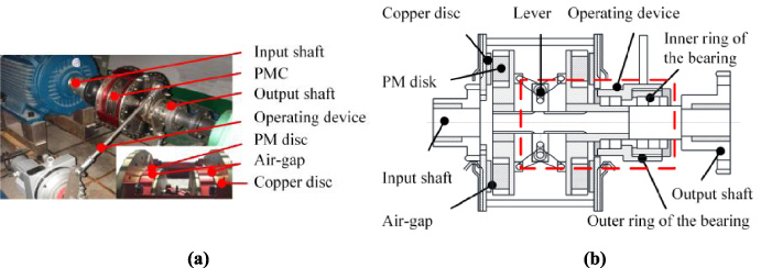
Conventional disc permanent magnet coupler. (a) Working picture of conventional disc PMC. (b) Structure of conventional disc PMC.
The traditional PMC has two types of disc and tube structure [5–7]. The disc PMC can adjust the transmission torque by changing the distance of air-gap. The tube PMC is by changing the intersecting areas of permanent magnets (PMs) and conductor [8–10]. Figure 1 shows the working picture and structure of conventional disc PMC. The input shaft drives the copper disc to rotate. The copper disc cuts the magnetic field lines from PMs to generate eddy currents. The magnetic field generated by the eddy current interacts with the permanent magnetic field to prevent the relative movement between the copper disc and the PM disc, thereby driving the PM disc to rotate, and the PM disc drive the output. The magnitude of the torque depends on the slip speed between the copper disc and the PM disc, so eddy current loss will occur on the copper disc when PMC is working, and the temperature of the copper disc will rise. The slip speed and torque of the conventional PMC is adjusted by changing the length of two air-gaps between the conductor and permanent magnet (PM). As shown in Fig. 1(b), the outer ring of the bearing is driven by the operating device, and the inner ring of the bearing is connected to the lever mechanism. The movement of the lever causes the two PM discs to move axially simultaneously, thereby changing the air-gap and transmitting torque. Changing the axial displacement need to overcome large magnetic attraction force, and hence operating device is easy to fail and it needs a large space volume. Many methods for efficiently varying fluxed-switching were extensively studied in the PM motor design [11–13]. A flux adjustable PMC with a movable stator ring is proposed [14]. The slip speed of the coupler could be adjusted by shifting the movable stator ring along the axial direction.
This paper proposes a new PMC with a synchronous rotating adjuster based on the fluxed-switching method. Fluxed-switching is used to change the magnetic flux in the copper disc. The new PMC avoids the complicated mechanical device existing in the conventional adjustable-speed PMC. A mathematical analytical model of the transmission torque of the PMC was established. The PMs temperature of the new and conventional PMCs was compared by the fluid-thermal coupling analysis method. The analytical models of electromagnetic torque and temperature are verified by the test.
PMC structure
Figure 2 shows the 3-D structure and 2-D section of fluxed-switching PMC [15]. It is a new topological structure with PMs as the center symmetry. The PMs are arranged by N–N and S–S magnetic poles and embedded in an aluminum plate. An adjuster for switching flux is designed between the PMs and the copper disc. The adjuster is made of some ferromagnetic sector blocks and a circular aluminum plate which is connected to the output shaft. The adjuster can be rotated 22.5° relative to the PMs by a helical flute and two cylinders. The relative angle between the adjuster and PM is called the flux angle θ f . In this way, the magnetic flux density transmitted from the PMs to the copper disc can be adjusted by flux angle θ f . Figure 2(b) shows that two cylinders pushes the outer ring of the bearing, and the inner ring of the bearing pushes the spiral chute. By the bearing, the axial movement of cylinders becomes the circumferential rotation of operating device. Compared with the structure in Fig. 1(b), the fluxed-switching PMC only needs to overcome the rotating friction torque, and does not need to overcome the attraction force of PM. So, the driving force becomes smaller and the reliability can be improved.

Fluxed-switching PMC. (a) The structural of fluxed-switching PMC. (b) Sectional of fluxed-switching PMC.
Figure 3 shows three different working situations of the proposed fluxed-switching PMC. (1) The ferromagnetic sector block cover two same poles of PMs when the adjuster is rotated to the position shown in Fig. 3(a). The PMC is fully open state and the slip speed is the lowest. The main flux path is from pole N-adjuster-copper disc-steel disc-adjacent adjuster-pole S. The flux switch is open, and there is the most flux in copper disc. So, the transmission ability is strongest at this situation. (2) The ferromagnetic sector block will gradually cover the two different poles of the PM when the adjuster is rotated to the position shown in Fig. 3(b). The slip speed gradually increases. The main flux path is divided into two paths: (a) pole N-regulator-copper disc-steel disc-adjacent adjuster-pole S. (b) pole N-adjacent regulator-pole S. The flux in the copper disc will gradually decrease. So, the transmission capacity will vary with the flux angle θ f at this situation. (3) The ferromagnetic sector block cover two different poles of PM when the adjuster is rotated to the position shown in Fig. 3(c). The PMC is fully closed state and the slip speed is the largest. The main flux path is from pole N-adjacent adjuster-pole S. The flux switch is closed, and there is the least flux in copper disc. So, the transmission ability is weakest at this situation.

Working principle. (a) Open situation. (b) Adjusting situation. (c) Closed situation.
Compared to the conventional PMC, there are the following advantages in the proposed coupler:
The PMC has simple and compact structure. The driving force of the PMC is lower because it is converted from the axial force to the tangential force. The demagnetization effect of the reaction eddy current fields on PMs is separated by the ferromagnetic sector block of adjuster. The larger the reverse magnetic field, the closer the working point of PM moves to the knee point. The influence of the eddy current heat to PMs is very low, since the adjuster is set between the copper disc and the PM disc.
Figure 4 shows the 3-D model of the PMC at closed state, which is simplified as follows: (1) The parts of non-magnetic materials are omitted in the model. (2) According to the periodic symmetry condition, only 1/8 model is established. The main parameters of the proposed PMC are shown in Table 1.

Geometrical parameters of the coupler.
Major parameters of the coupler
To determine the main design parameters of the PMC quickly, a 2-D electromagnetic field analysis model was established based on MEC. Figure 5 shows the analysis model of MEC of PMC.
For any closed magnetic circuit, the magnetic circuit follows the direction shown by the dashed line in Fig. 5. According to Kirchhoff’s second law of the magnetic circuit, the algebraic sum of the magnetic voltage drop of the magnetic circuit is equal to the algebraic sum of the magnetomotive force in the magnetic circuit, the following equations can be given by

The analysis model of MEC.
According to the magnetic circuit model, the path reluctance can be calculated as:
Therefore, the amplitude of static air gap flux density can be obtained by
The eddy current density J in the stator is given by B
g
[17]:
The power loss of the PMC can be obtained by induced eddy current density J.
Furthermore, the output power P and transmission torque T of the PMC can be obtained.
Magnetic field analysis
When the adjuster rotates at different positions, there are different flux in the ferromagnetic sector block as shown in Fig. 6. As the flux angle θ f increases, the less flux come to the steel disc. When the θ f = 22.5°, the magnetic saturation of the ferromagnetic sector block may happen.
The PMC adjusts the rotating speed and torque by changing the flux angle. Figure 7 shows the magnetic flux φ through the sector block under the six different flux angles (0°, 4.5°, 9°, 13.5°, 18°, 22.5°). It shows that magnetic shield is better at 18°. The air-gap flux is 0.0024 Wb at 18°, which is 44.4% of θ f = 0°. The reason for this phenomenon may be that the sector block cannot completely shield the magnetic circuit, and the magnetic flux leakage is more than at 18°.
Torque characteristic
Figure 8 is the 3-D surface graph calculated by the transient three-dimensional electromagnetic field finite element method. It shows the torque-slip speed distribution at different flux angles when the material of copper disc is red copper. The bigger transmission torque can be obtained when the slip speed is slow. It can be seen that: (1) when the flux angle θ f changes from 0° to 22.5°, the transmission torque decreases. However, the torque is increased a little when θ f changes from 18° to 22.5°. (2) When the slip speed Δn is 140 rpm, the torque reaches a maximum value of 1670 Nm at θ f = 0°. (3) The torque reaches the minimum value of 302 Nm at θ f = 18°, which indicates that the PMC cannot completely cut off the torque transmission.
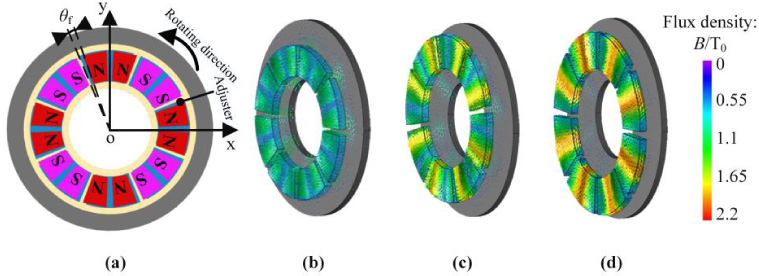
Angle and rotating direction of adjuster relative to PMs, and flux density through adjuster and steel disc at 3 angles. (a) Angle θ f . (b) θ f = 0°. (c) θ f = 9°. (d) θ f = 22.5°.

Air-gap flux φ under the six different flux angles.
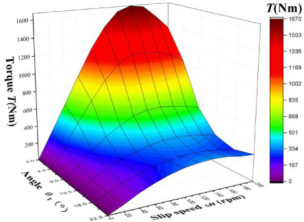
The torque-slip speed distribution at different flux angles.
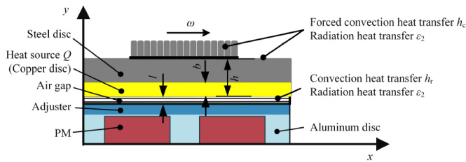
Thermal-fluid field mathematical model of the couplers.
Thermal-fluid field mathematical model fluxed-switching PMC
It can be seen from the analysis of the electromagnetic field that most of the eddy current is generated in the copper disc, so the power loss of eddy current can be set in the copper disc. The thermal-fluid model is established, as shown in Fig. 9.
The eddy current heat is transferred from the copper disc to the steel disc by heat conduction. The basic equation is:
The other heat transferred to the PM and air is mainly carried out by convection and radiation. The basic equation is:
The simulation model of the thermal-fluid field includes fins, copper disc, adjuster and PMs as shown in Fig. 10(a). Figure 10(b) shows the 1/8 fluid-thermal coupling model, including the PMC and the surrounding air. To determine the boundary conditions, we assume that the air region 1 near the copper disc is the moving air domain, which rotates with the copper disc. Similarly, the air region 2 rotates with the adjuster and PMs. The region outside the moving air domain is a static air domain.
The Reynolds number R
e
in the air gap can be obtained by [18]:

Thermal field calculation model and CFD model.
The thermophysical properties of various parts
The CFD model involves rotational flow, and the RNG k–ϵ turbulence model is introduced. The RNG k–ϵ model is illustrated as follow [19]:
Table 2 shows the thermophysical properties of the parts.
The power loss is calculated as the heat source, the heat generation rate formula is:
The numerical simulation of the transient thermal-fluid field is carried out by computational fluid dynamics (CFD) when the ambient temperature is 22 °C, θ f = 0°, input speed n 0 = 1500 rpm and Δn = 200 rpm. Figure 11 shows the air velocity around the fin and the thermal convection coefficient of fin. It can be seen that the air velocity closer to the blade is lower, and many vortices are formed on the fin surface. Figure 12 shows the temperature distribution of each parts of the PMC. Figure 12(a) shows that the maximum temperature is 133 °C on the copper disc. Figure 12(b) shows that the temperature distribution of sector block. Under the same conditions, Fig. 13 shows comparison of temperature distribution on PM of the two types. The PM temperature difference is about 23 °C between the new and conventional PMC, which indicates that the adjuster can insulate well the heat transfer to the PM. PMs of the conventional PMC will be demagnetized due to high temperature (80 °C). In order to show the temperature distribution of each parts of the PMC clearly, a line is defined along the z-axis near the center of the PM, and the temperature of each part is mapped to this line, as is shown in Fig. 14. As can be seen that, (1) the temperature of the steel disc drops fast as the fins can dissipate lots of heat. (2) The air-gap temperature increases with the axial distance. (3) The trend of the PM to adjuster curve does not change much and the temperature is about 64 °C.

Air velocity around the fins and thermal coefficient. (a) Air velocity. (b) Thermal convection coefficient.
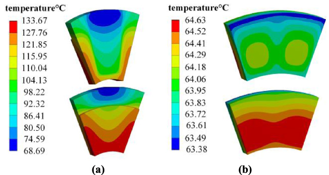
Temperature distribution of the model. (a) Copper disc. (b) Ferromagnetic sector block.
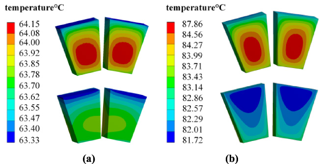
Comparison of temperature distribution between PM between the two types. (a) New PMC. (b) Conventional PMC.

Temperature curve along the axial direction.
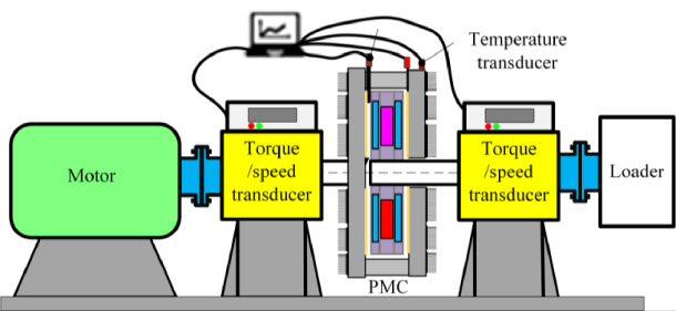
Schematic for test of PMC.

Bench test of PMC.

The pictures of adjuster and fins.
PMC bench test
The schematic diagram of PMC test, the bench test picture of PMC and the picture of adjuster and fins are shown in Fig. 15, Fig. 16 and Fig. 17 respectively. It mainly consists of motor, PMC, torque/speed sensor, temperature sensor, data collection system and loader. In the process of testing, the eddy current brake is selected as loader to verify the theoretical method for the static prediction of PMC torque. To analysis the influence of different electrical resistivity, two copper plates are tested. One is red copper whose resistivity is 1. 67 × 10−8 Ω ⋅ m2∕m for parts B and C, another is brass whose resistivity is 7 × 10⁻⁸ Ω ⋅ m2∕m for part D in this section.
Verification of FEM
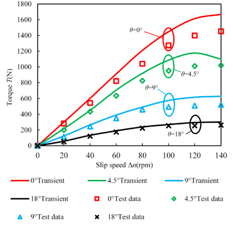
In the test, the rated speed of the driving motor is 1500 r/min. The PMC is adjusted from the closed state to the open state by the regulating device. The slip speeds and torques were recorded at the switched flux angles of 18°, 9°, 4.5° and 0°, respectively. Figure 18 shows the slip speed-torque curve for 3-D transient and test data. The data of 3-D transient are close to the test data. At low slip speed (Δn < 100 rpm), the torque value of 3-D transient agrees well with the experimental measurement, and the error is within 10%. However, as the slip speed increases, the error becomes larger and larger, and the error exceeds 21% at Δn = 140 rpm. Although the 3-D transient method has considered the influence of the reverse eddy current magnetic field at high speed, the temperature influence caused by the eddy current loss make the errors.
The curves of the eddy current loss power of the PMC experiment.
Figure 19 shows the comparison between 3-D CFD and test results of the temperature. As can be seen, (1) when the switched flux angle is constant, as the slip speed continues to increase, the temperature of parts of the PMC also continues to increase. (2) The simulated value is slightly larger than the test value. The higher the temperature, the greater the error, and the maximum can reach 11.4%. Maybe there are three reasons for the error. One is the influence of high temperature to the transmission torque. Another is the monitoring point.

The pictures of adjuster and fins.
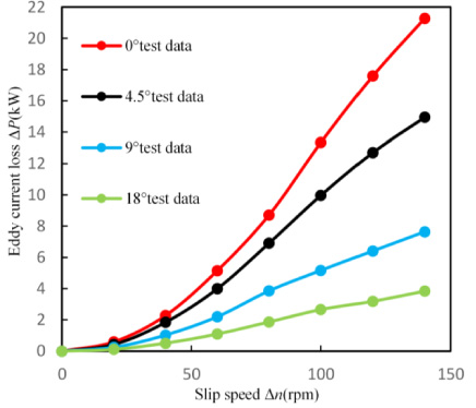
The curves of the eddy current loss power of the PMC experiment.

The curve of the transmission torque of the PMC matched with the quadratic load.
Generally, permanent magnet coupler has the effect of energy saving only when it is used to regulate the speed of pumps and fans. Figure 20 shows the curves of the eddy current loss power of the PMC experiment. The formula for the eddy current loss power efficiency is:
To get the best effect of speed control, the material of copper plate is made of brass. The rated speed of input shaft is 1500 rpm. The horizontal axis is the efficiency of the PMC which is equal to the speed ratio of the output shaft and the input shaft, which can be controlled by changing the flux angle θ f . Figure 21 shows the transmission torques of the PMC matching the secondary load. There are two points, A and B, which is intersected by the transmission torque curve with θ f = 0° and θ f = 18° and the quadratic load line, respectively. If the intersections are at the left of the highest torque point, the system will not operate stably. The efficiency range is from point A to point B, and it is also the efficiency range of the PMC. Therefore, for the quadratic load, the efficiency range of the PMC corresponding to the switched flux angle 0°–18° is about 75%–96%.
According to the Affinity Laws, the speed changes of the same pump or fan will produce cubic changes in energy under the same working conditions. Considering the energy loss of the system, the energy saving of PMC can be calculated by the square relationship in practice. The formula for energy saving efficiency is:
This paper proposes a novel fluxed-switching PMC, which can adjust the torque by changing the magnetic flux. It can be used for the speed regulation and energy saving of pump and fan type. The torque is analyzed by the 3-D transient method. The test result shows that at low slip speed (Δn < 100 rpm), the torque value of 3-D transient agrees well with the experimental measurement value, the error is within 5%, but the error exceeds 21% at Δn = 120 rpm. The temperature rise test shows that the test data and the FEM data are in good agreement under the maximum load condition. The maximum temperature error is 11.4%, and the maximum temperature is much lower than the PM Curie temperature. The efficiency range of the novel PMC can reach 75%–96%. In the future study, the temperature influence should be considered to further improve the accuracy of the torque calculation model.
Footnotes
Acknowledgements
This work supported by the Natural Science Foundation China under (51741701 and 5177700) and Beijing Natural Science Foundation (3182007).