
Abstract
In this paper, we propose an order reduction method which can be applied in the approximated analytical model for linear permanent magnet machines (LPMMs). The proposed model takes the periodic boundary condition into account the Poisson and Laplace equations, hence, the analytical solution requires low harmonic orders in each subdomain. The magnetic results show that the proposed model can maintain high accuracy while taking low computational time. 2D finite element computations, as well as measurements, validate the proposed model. The proposed model in this paper can also be further applied in permanent magnet machines with high pole and slot combination, to reduce the computational time.
Introduction
Linear Permanent Magnet Machines (LPMMs) can directly obtain linear motions without intermediate transmission mechanisms, which has played a quite important role in industrial applications, such as maglev transportation, distributed power generation, robotic systems [1–3]. For LPMMs, the accuracy of magnetic field calculation directly affects its output performance.
At present, different numerical and analytical approaches have been developed to determine and optimization the magnetic field in the design stage, each method has its merits and defect. For example, the FEA method can effectively take the saturation effect into account, but it takes a long time and the physical relationship between parameters in the magnetic field cannot be directly reflected [4–6]. Considering the time-consuming, the analytical method with fast computation and acceptable accuracy is used in the initial design, such as magnetic equivalent circuit (MEC) method, Schwarz-Christoffel conformal mapping (SC) method, sub-domain (SD) method, etc [7–9]. MEC is suitable for a rough estimate design, the precision of force calculation needs to be improved [10]. And SC mapping is more accurate than that of MEC which can be employed for fine-tuning, however, the results of SC are affected by the slot size slot significantly, the error increases with the increase of slot opening size [8].
SD method could obtain more accurate results for predicting magnetic performances. In [11–13], subdomain analytical model is established to analyze the LPMMs magnetic performance in the 2-D Cartesian coordinate system, the no-load condition and armature reaction field are calculated, respectively, meanwhile, the results are verified by FEM and experiment. However, as the linear machine modeled in the Cartesian coordinate system, too many unknown coefficients increase the calculation complex. To address the problem, the polar transformation is proposed in [14–17]. In [14], a polar presentation of the machine geometry is proposed and the subdomain method is applied to calculate the magnetic field. Three different analytical models with different radius of curvature L re = 500, 1000, 2000 mm are compared, and the Fourier harmonic order is set as 400, 600, 1000 respectively. there is good agreement between the analytical results and experiment. However, for this analytical model, the computation time is determined by the extended radius size and high harmonic order, with the increase of radius and harmonic number, the calculation result becomes more accurate, and the computation time will significantly increase.
The general principle for the extended arc radius selection Generally speaking,in the conversion between LPM and radial flux permanent mangnet machine (RFPMM) is usually ignored in pervious studies. Moreover, the large extended arc air region needs high harmonic order in solutions and results in high computational time. This would make this method is hard to be applied in the initial design of LPM. Therefore, an order-reduced model is desired. To overcome the problems, a conversion theory is presented for surface-mounted PM machines modeled in different coordinates in this paper, viz., the polar coordinate, and the Cartesian coordinate. The general and simple conversion theories are derived. With the proposed conversion theory, different topologies of machines can be modeled and analyzed in one coordinate which can simplify the design process.
This paper is organized as follows. In Section 2, the investigated LPM machine and its main parameters are provided. Afterward, the detailed calculation strategy is introduced, the general solutions of each subdomain which considering the periodic boundary condition are expressed in Section 3. The results are then discussed in Section 4. Finally, the conclusions are drawn.
Investigated machine
In this paper, the LPM machine without considering the slot effect is investigated as stated in [14]. The linear machine is consists of a primary stator and secondary mover, the PM is mounted on the surface or mover alternately, and between the stator and mover, the air gap is used for energy conversion. The studied magnetic model is shown in Fig. 1.
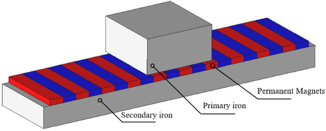
Structure of a LPM.
The main parameters are shown in Table 1.
Main parameters of LPM
In this paper, the Fourier series and the variables separation method are adopted to solve the magnetic field. Generally, the following assumptions are utilized in analytical model for the computation process simplification:
no magnetic leakage in the linear machine, the permeability of iron is infinite. the saturation effect is ignored the generator operates under non-saturation open-circuit conditions. Foucault’s/eddy currents and axial end effects in the magnetic field are ignored.
Approximate model and perdioc condition
The analytical model of the linear machine in Cartesian coordinates is shown in Fig. 2(a). It can be seen that if the end effect of primary and secondary are considered, the magnetic field needs to be divided into 6 subdomains, which will introduce many boundary conditions and unknown coefficients, making the magnetic field calculation complicated. To overcome the computation complex, the simplified assumptions are used as stated in [18], the transformed model is shown in Fig. 2, The parameters in the polar system are calculated as:
When cylindrical coordinates are used, the solutions arising from the resolution of the PDE contain Bessel’s functions. This leads to some numerical diffi and a lack of accuracy without sufficient harmonics. These problems decrease the reliability of the design tool. A linearization assumption at the mean radius (Fig. 2) is used here to overcome the problems encountered using cylindrical coordinates. This approach is valid when the curvature effects are considered. The research shows that the difference caused by the curvature is small, this is true for most electromechanical devices because the air gap thickness is usually much lower than the other dimensions of the system. This issue will be discussed in Section 4.2..

Analytical model of LPM. (a) Model in cartesian coordinate. (b) Model in polar coordinate.
Both region I and II (PM and airgap) and slot region are satisfied with Maxwell’s equations. For the 2D case in the polar coordinate system, by introducing magnetic vector potential, the governing function is [19]
By using the variable separation approach, the general solutions of the vector potential in (1) can be calculated as
The periodic boundary condition is added in this paper to reduce the model order and computation time. The periodic number of the magnetic field is set c = GCD(n
s
⋅ c, p ⋅ c), and the vector potential A can be expressed as
By applying the periodic boundary condition, the traditional general solution expression in (2) can be transformed to (5). It can be observed that the harmonic order is c times lower than that of the traditional method, which would result in lower computational time while maintaining accuracy. This is very helpful to improve the calculation quality of the approximated model in this paper. Moreover, the machine with high poles and slots can also use this approach.
To determine the equivalent radius in Fig. 2, the magnetic flux densities in Cartesian and polar coordinates are calculated by the method in [17]. Moreover, the linear curve fitting technique in the Matlab toolbox is used to enhance universality, the expression is obtained as follows:
Firstly, according to the equation, the range of radius R is determined. In this paper, we choose the error tolerance less than 0.5%, therefore, the minimal R g can be deduced as R g ≥ 540.3h pm . Then, based on the R g value, the c in (4) can be evaluated. Finally, the extended length of L ext is ensured by R and C. The diagrammatic illustration of the proposed technology is presented in Fig. 3(b).
As for the analytical model, the additional back iron L ext is set as 40 mm to avoid interaction between the PMs at the end position. The corresponding main parameters of the equivalent model are given in Table 2.
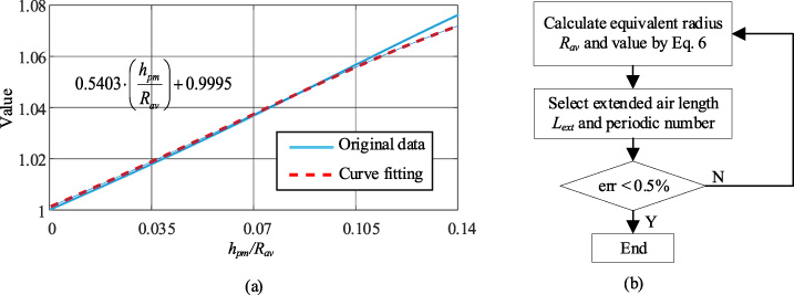
Calculated diagram of the approximate analytical model. (a) Curve effect coefficients (b) Diagram of calculation.
Equivalent Parameters of RFPM
For the 2D case in the polar coordinate system, by introducing magnetic vector potential, the governing function in region I (PM region) is
The magnetization in the tangential direction is zero for the radial magnetization. The magnetization model of permanent magnets under the mover reference coordinate system is shown in Fig. 4. The range that starts from N p θ p to ±π is zero due to the absence of PM. Therefore, the Fourier expression of the PM should have a periodicity of 2π.
The radial and the tangential component of the magnetization vector
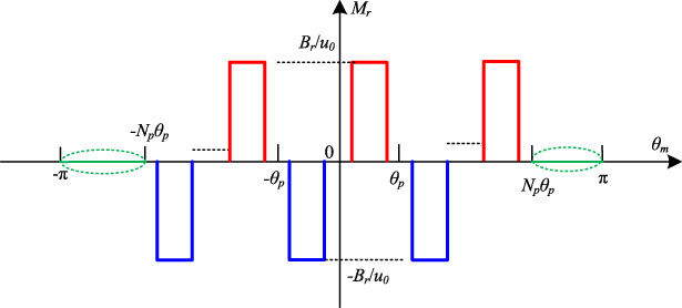
PM magnetization model of LPM.
The magnetic strength of tangential component is
The general governing equation in region 2 is:
Applying the same logic (H
θ = 0 at R
sb
,), the general solution of region 3 is:
It should be noted that each domain is connected, so the interface conditions should meet boundary conditions. The connections between region 1, region i and region 3 at R
s
is:
The unknown coefficients can be calculated by applying Fourier series expansion and boundary conditions. Afterward, the radial and tangential flux density components are obtained as follows:
Flux density in the air gap
To verify the analytical model proposed in this paper, the FE models with linear and non-linear magnetic cores are developed by the commercial software JMAG. It should be noted that the semi-closed slots are applied in the model of LPMSM and the stator is located in the middle and end position, respectively.
The flux lines distribution at the two positions is illustrated in Figs 5 and 6.
In this model, the extended air gap length L ext is set as 40 mm. Fig. 5 compares the flux density in the middle of the air gap. It shows that the results predicted by the proposed method agree well with those obtained from the FEM prediction. To verify the proposed model further, the magnetic flux densities in the end position are also compared in Fig. 6. It can be observed that the results from proposed model matches well with FEM.

Results of the magnetic field in the middle position. (a) flux-lines distribution of linear machine (b) the flux density distribution of linear machine.

Results of the magnetic field in the end position. (a) flux-lines distribution of linear machine (b) the flux density distribution of linear machine.
According to the Maxwell tensor equation, the cogging torque of the radial model can be computed by
With regards to the LPMSM, the thrust force is one of the main performances of the machine. According to the lever principle and combining with the correction equation, the thrust force can be converted as:
Figure 7 shows the trust force of the prototype. As shown in Fig. 7(a), the proposed method is able to predict the cogging torque waveform with a high degree of accuracy.

Comparison of thrust force. (a) Comparison with non-linear FEM, (b) Comparison with the experimental result.
The results obtained by the analytical model and experiment are compared in Fig. 7(b). It can be seen that the proposed method is able to predict the flux waveform with high accuracy.
The CPU time is also compared between the FEM and analytical model. This was done on a core i7 processor and 16 GB installed memory with 64-bit operating Windows 10 system.
Comparing with existing literature [20], the LPMSM with 2000 mm extended arc air region takes 20 sec to calculate the magnetic performance, even the slots are not considered. As for the model presents in this paper, only 1.3 sec is needed, it takes much less CPU time than the existing analytical approach.
In terms of computation time as shown in Table 3. The FE model requires almost 2 mins to compute the magnetic performance for one electrical cycle. Comparing with existing literature [20], the LPMSM with 2000 mm extended arc air region takes 20 sec to calculate the magnetic performance, even the slots are not considered. As for the model presents in this paper, only 1.3 sec is needed, it takes much less CPU time than the existing analytical approach.
Although a similar error exists when comparing analytical results to experimental values, it is still acceptable and thus, it can be regarded as a meaningful approach that could save time and achieve an acceptable result.
Comparison between different methods
Comparison between different methods
In this article, we have presented an analytical model that can quickly predict the flux density distribution. The model is developed based on the approximate approach, which rolling the LPM into a rotary machine. In this model, we introduce the peridioc boundary condtion to reduce the order of the model, the equation of correction factor is adopted to obtain the peridioc number and guarantee the accuracy, and high accuracy results could be obtained. The results show that the magnetic flux densities matched well and as well as the detent force. The FEM and experiments are both conducted.
This powerful tool can then be used for the fast and accurate design of PMs magnetic couplings or to be integrated within evolutionary optimization procedures. Moreover, the peridioc boundary condition can also be used in the machine with high slot and pole combination, to reduce the computation time.
Footnotes
Acknowledgements
This work was supported in part by the National Nature Science Foundation of China under Grant 51907027, and in part by BUCEA Young Scholar Research Capability Improvement Plan under Grant X21081.