
Abstract
The aim of this article is the mathematical modeling of the car wheel with an energy harvester. The car wheel will be represented as a 3-DoF robotic kinematic chain. The Matlab program has been used to simulate the movement of the car wheel and the movement of the electromagnetic energy harvester located on the tire of the wheel. Simulation of the movement of the energy harvesting element allows us to compute the energy harvested in such a system.
Introduction
In this paper, the mathematical model, which allows to simulate the movement of the electromagnetic energy harvester with a magnetic spring placed on the tire of the car wheel is presented. The energy harvester movement and wheel rotation and deformation are mathematically modeled using the Denavite-Hartenberg notation used in the robotic systems. The mathematical model allows us to determine the best resonance frequency to maximize the harvested energy.
In the literature many models of the car wheel can be found. In the rigid model the tire belt is represented as a rigid ring with single point of contact with the road roughness through the spring, the rigid ring is connected with an axle of the wheel by springs and dampers. This model doesn’t consider tire deformation, but only the change of the position of the axle. The point contact with the road leads to smoothing of the irregularities of the road [1]. In the multibody model, elastic belts (discrete point mass network) are connected to the axle by springs: both radials and tangentials, rotational and linear. This model is accurate but it requires heavy computational power and determination of all parameters (each point is connected through springs) [1–3]. In the finite element model, the model is using detailed geometry of the tire. It uses FEM (finite element method) to compute dynamic behavior. It is the most accurate method that requires less external parameters but requires the heaviest computational power, which means longer time of simulation [1,4,5]. In the modal model relations between inputs and outputs are identified using modal dynamics of the tire, derived through FEA (finite element analysis) or experimental analysis, it is represented as a black box [1,3,6]. In this model nonlinear effects of the force variations, the transient slip etc. are not considered because the model is linear. Also the relations between forces and parameters are not clear [3]. Nowadays, the most popular in the car industry are modal models [3,7].
The proposed model presented in this article is simple (but it could be more complex if more than 3-DoF are considered) and it doesn’t require a heavy computational power. It considered the deformation of the tire due to the road roughness and also the returning of that tire to its original shape. The relations between forces and parameters are well known and the forces acting on the wheel can be considered as nonlinear and depending on the movement of the tire. These model doesn’t take into account all changes in the tire as the FEM or modal method does, such as changing of the pressure in the tire or heating of the tire, but it allows to analyze the movement of the point on the tire during its rolling movement.
The energy in a car is harvested mainly from the movement, for example, from the vibration of the suspension or during braking, and can be used to power a sensor system, such as tire pressure monitoring systems or active dampers [8–10]. The energy extracted from tire deformation using the piezoelectric systems like in [11,12] is the most popular, but it is possible to use other systems, for example the electrostatic system [13]. From the vibration and rotational movement of the wheel, it is possible to harvest energy using the electromagnetic generator like in [14–16]. The limitation of such systems lies in a resonance frequency. Therefore, most of these systems work out of resonance, or have an adjustable resonance frequency, or are nonresonant [17,18]. The frequency range of the vehicle vertical vibration is up to 25 Hz [19], but depends on the road roughness and vehicle speed [20,21].
Most energy harvesting systems consist of a generator, a voltage regulator, a storage element, and a system to adjust the resonance frequency. The resonance frequency can be set by changing the elasticity coefficient of the spring or by changing the rotational speed. It can be done, for example, by changing the position of the proof mass to the position where the distance from the center of the wheel mass is equal to the length of the pendulum [9]. The adjustment of the resonance frequency can be also done by changing the deflection of the cantilever beam with the moveable proof mass [18,22] or the repulsive force of the magnet [17]. Setting the resonance frequency can also be done by changing the distance between the magnets as in [8] or by using the repulsive force between the moveable magnets that deforms piezoelectric elements [23].
Wheel model with part of car suspension
Wheel
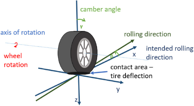
The movement of the car wheel is rotational in the rolling direction. It is assumed that the deflection can be presented as a vertical movement of the wheel. The deflection depends on the movement of the car on the road roughness. Due to that deflection, the wheel is not moving exactly in the intended rolling direction. During the car movement the wheel changes the direction of its rotation, then a camber occurs which also depends on the deflection of the tire [24].
Possible movements of the car wheel.
As can be seen in Fig. 1, five possible movements can occur in the car wheel:
Rolling of the car wheel — the rotational movement with an axis of the rotation orthogonal to the rolling direction and placed near a centre of the wheel, Deflection of the tire, which depends on the roughness of the road, the linear vertical movement, Divergence from the intended rolling direction and change of that direction – rotational movement with an axis of the rotation orthogonal to the road surface, Camber angle – the rotational movement with an axis of rotation parallel to the rotation direction and projected on the road surface, Return of the tire to its original shape after a rotation – the linear movement.
Therefore, a kinematic chain representing each of described movements of the wheel with an energy harvester has 5 degree of freedom (DoF) and contains 5 joints: the first - prismatic, the second - rotational with an axis of the rotation ortogonal to the road surface, the third - rotational with an axis of the rotation parallel to the road surface and to the rolling direction, the fourth - rotational with an axis of the rotation parallel to the road surface and ortogonal to the rolling direction, and the fifth - prismatic. This representation is proper for the assumption that the movement of the tire due to the road rougness is only vertical, which is sufficient for the model with the energy harvested from a vertical movement. Actually, the elasticity of the tire should be represented as a set of rotational joints to represent the deflection in each direction. However, the simplest way to represent the movement of the car wheel with the energy harvester is possible by using a 3-DoF kinematic chain with two prismatic joints representing the deflection and return of the tire to its original shape and one rotational joint representing the wheel rolling.
The most popular car suspension model is the quarter car suspension model (2-DoF) [25]. The suspension is presented by one quarter of the car mass m c (sprung mass), the elasticity coefficient k sa and the damping coefficient b sa of the shock absorber (in this case a passive damper) and by the axle mass of the wheel m w (unsprung mass), the elasticity coefficient k t and the damping coefficient b t of the tire. In this paper, only the part of this system that concerns the wheel part with the tire damping coefficient and the elasticity coefficient (Fig. 2) is considered.
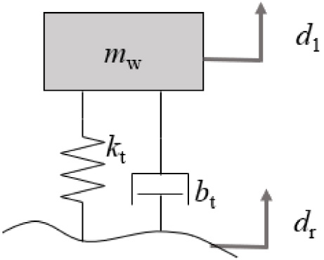
Model of the wheel part of the car suspension.
The Eq. (1) describing the wheel part of the suspension system is a modification of the suspension equation of the quarter-car.
The road profile can be modeled according to the road roughness classification of ISO 8608:2016. Equation (2) describes the roughness of the road.
Kinematic chain of the wheel
To calculate the energy possible to harvest, it is necessary to consider the rotation of the wheel and gravitational force acting on it. The behavior of the system can be described using a homogeneous transformation [29–33]. The wheel and tire movements, in the simplest way, can be represented by two prismatic joints and one rotational joint, as in Fig. 3. The prismatic joints represent the deflection of the tire and the return of the tire to its original shape, and the rotational joint represents the rotation of the wheel axle. The energy harvester is located on the tire, and it harvests the energy from the tire shape changes; therefore, on the kinematic chain, it should be near the second prismatic joint.
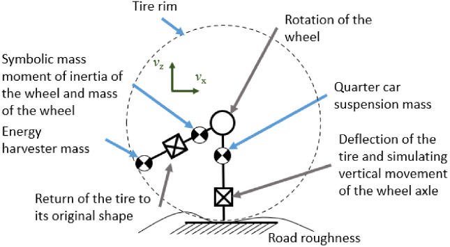
Kinematic chain of wheel, tire and energy harvester.
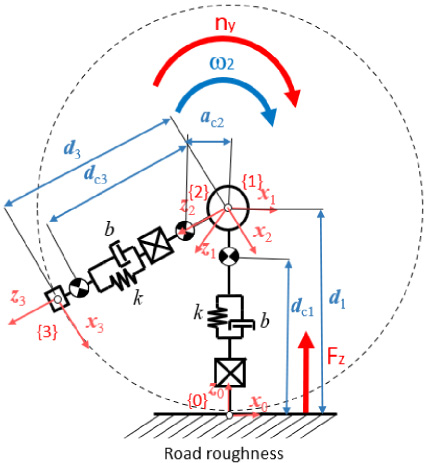
Kinematic chain of wheel, tire and energy harvester with spring and dampers and graivty centers.
To describe the tire in the movement of the wheel tire and the energy harvester, the Denavite-Hartenberg notation [34] is used. In Fig. 4a kinematic chain with masses of links represented by their gravity centres and axes of links is shown. The first gravity centre is a wheel imbalance which can be described by a parameter dc1. The second gravity centre symbolizes the moment of an inertia of the wheel and its displacement can be described by a parameter ac2. The third gravity centre is the energy harvester, and its displacement can be described by a dc3 parameter. Above prismatic joints there are dampers and springs; they are symbolized by a stiffness coefficient and a damping coefficient of the tire.
The kinetic parameters for the kinematic chain without gravity centers are shown in Table 1 and the kinematic parameters for gravity centres are shown in Table 2, where: i is the ordinal number of the link, a i is the distance between axis z i and zi−1, 𝛼 i is angle between axis z i and zi−1, d i is the distance between the axis x i and xi−1 and 𝛩 i is the angle between the axis x i and xi−1, symbol ∗ above letter means that it is variable.
Kinematic parameters for the kinematic chain of the wheel with tire and energy harvester
Kinematic parameters for the kinematic chain of the wheel with tire and energy harvester for gravity centres
The linear and rotational kinetic energy and then inertia matrix
The Jacobian matrix contains the Jacobian of the linear speed
The centre of the base joint
Therefore, it is necessary to calculate a homogeneous transformation regarding each joint as the last in the kinematic chain and also regarding each gravity centre as the last joint of the kinematic chain. A homogeneous transformation for the kinematic chain with
The transformed matrices of Jacobians for each gravity centre are shown below:
The equations of forces and the torque of the wheel can be written using the Euler–Lagrange equation. In the equation, also gravity forces, spring forces, damper forces and road roughness should be considered. The forces acting on the first joint depend on the gravity forces, the spring forces of the tire, the damping forces, and the roughness of the road. The forces acting on the second joint depend on the torque exerted on the rotation axis. In order to keep nearly constant rotational speed of the wheel, the driving torque of the wheel has to equal the rolling friction torque. It is hard to achieve in reality because the rolling friction torque depends on the dynamic radius of the wheel, which depends on the deformation of the tire [24,35]. In the third joint, spring forces and damper forces should also be considered. The equations for the movements of the movements of the car wheel and the energy harvester movements are the canonical forms of the Euler–Lagrange equation ((10)).
The force F1 acting on the first joint is equal to the suspension mass of the suspension mass of the gravity force of the quarter car suspension mass, of the wheel and the energy harvester mass, and to the force of the spring and damper of the tire ((13)). It was assumed that the wheel rotates with the constant velocity; therefore, the torque τ2 acting on the second joint is equal to the driving torque minus the rolling friction torque ((14)) [35]. Signs of these torques are determined by the direction of the z1 (Fig. 4) axis and the direction of the rotation of the joint. The force F3 acting on the third joint is equal to the force F1 expressed in the energy harvester coordinate system and to the spring and damper force of the tire ((15)).
Based on the canonical equation of the car wheel and the energy harvester movement (10) it is possible to model and simulate these movements in the Simulink/Matlab program (Fig. 5).
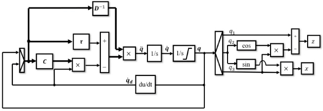
Implementation of the canonical equation that describes the movement of the energy harvester placed on the tire of the wheel.
In Fig. 5 the block
Knowing the value of the radius of the car wheel, the damping coefficient, the initial deflection of the tire, and masses of the elements, it is possible to simulate the movement of the energy harvester, which allows one to determine the resonance frequency and as a result to maximize the harvested energy. Table 3 shows the simulation parameters. To simplify the interpretation of results, it has been assumed that the road roughness is sinusoidal.
Parameters of the wheel with the energy harvester and the environment in the simulation
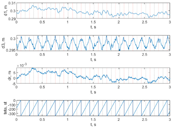
In Fig. 6 results of the movement of each kinematic joint are shown. The roughness of the road (d r in Fig. 6) acts on the deflection of the tire, causing the periodic motion of the first joint (d1 in Fig. 6). The rotation of a wheel (teta in Fig. 6) can be represented as a periodic motion with the value changing from −360 to 0 degrees. Therefore, the movement of the second joint can be represented as a periodic sawtooth signal. It can be seen that when the energy harvester is near the road, the road roughness acts on the third joint (d3 in Fig. 6). It occurs when the angle of rotation of the wheel is equal to 0° or −180°. When the harvester is near the road (when the angle of the wheel rotation is equal to 0°), gravitational forces acting along the z3 axis cause an extension of the distance between the road surface and the centre of the wheel. When the harvester is exactly above the road surface (when the angle of wheel rotation equals −180°), gravitational forces acting on the contrary to the z3 axis cause a shortening of the distance between the road surface and the centre of the wheel. The deflection of the tire acts on the movement of the energy harvester and allows to harvest the energy from the movement.

Results of the movement of each kinematic joint and road roughness.
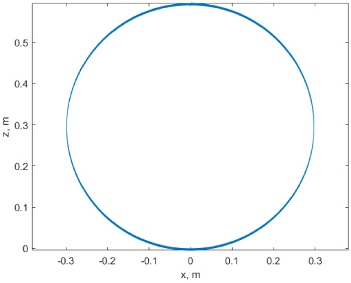
Trajectory of the movement of the energy harvester placed on the tire of the wheel.
The trajectory of the movement of the energy harvester placed on the tire of the wheel is shown in Fig. 7. It can be seen that an almost circular trajectory with changes in a radius near 0 m and 0.6 m, when the energy harvester is near the road and exactly above the road (when the position of the second joint is 0° and −180°) – the line is thicker. The zoom-in of this thicker line is shown in Fig. 8. It can be seen that there are actually several lines, which correspond to change of the displacement due to the road roughness.
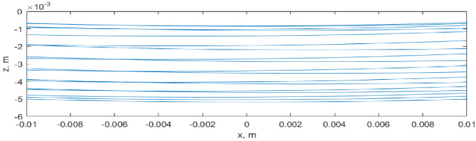
Trajectory of the movement of the energy harvester placed on the tire of the wheel.
The movement of the energy harvester with regard to the base coordinate system is shown in Fig. 9. It can be seen that the energy harvester is moving from near 0 m (plane-road surface) to near 0.6 m (almost diameter of the wheel). The change between nearest lowest and highest points, which corresponds to one rotation of the wheel, is not greater than the diameter of the wheel.

Results of the the movement of energy harvester in regard to the base coordinate system.
To show the influence of road roughness on the movement of each kinematic joint, it was assumed that a car with the same parameters is moving on the average road surface (Fig. 10). The road roughness (d r in Fig. 10) acts on the tire deflection, causing the movement of the first joint (d1 in Fig. 10) according to the road roughness. The rotation of the wheel (teta in Fig. 10) is the same as in Fig. 6. When the harvester is near the road (when the angle of the wheel rotation equals 0° gravitational forces acting along the z3 axis cause an extension of the distance between the road surface and the centre of the wheel. When the harvester is exactly above the road surface (when the angle of rotation of the wheel equals −180°), gravitational forces acting on the contrary to the z3 axis cause a shortening of the distance between the road surface and the centre of the wheel. Near these two points, the road roughness and the first joint acting on the third joint, cause additional changes in the movement of the energy harvester.
Results of movement of each kinematic joint and type C road roughness.

Model car wheel model with energy harvester (a) third joint with energy harvester near road, (b) third joint with energy harvester when tire is returning to its shape, (c) placement of the energy harvester on the inner layer of the tire.
The energy harvester is placed in the inner layer of a tire (on a tire rim), like in [36]. It is shown in Fig. 11. It is the inertial energy harvester, therefore, the movement of the tire (force acting on the third joint) is acting on the chassis of the harvester and causing the movement of the harvester and indirectly the movement of the magnet. The energy harvester consists of a magnet between two magnetic springs and the coil wounded around the chassis. Therefore, in order to obtain exact results these two springs should be added to the equation, and the whole system would be 4-DoF. Assuming that the proof mass on the electromagnetic energy harvester is moving exactly as the energy harvester placed on the wheel rim (for simplicity), we can estimate the energy that could be harvested using a linear generator (these values will be higher than for 4-DoF system). Damping force from the voltage induced in the coil was in this case omitted. Therefore, harvested power will be lower then the shown estimated one. It was assumed that the element that harvests energy in the energy harvester is moving exactly like the whole energy harvester placed on the car wheel rim. Therefore, the physical composition of the energy harvester (that means two springs between magnet, which harvest energy is moving) is not considered in that case. That movement will be investigated in future work. The goal was to present new modeling method of the whole energy harvester placed on the car wheel rim movement, so each type of a harvester can be presented in such way. Maximum power is harvested, when the resistance of the load equals resistant of the coil. The single coil wounded around chassis of the harwvster around the z3 axis has N turns (N = 200), radius of the coil is r
c
= 0.006 m, the copper wire of the coil is round and its radius is r
d
= 0.0001 m. In order to obtain the maximum power the resistance of the load equals resistance of the coil, it is about R = 4.13 Ω. It was assumed that the magnetic flux density vector component in the x3 axis B
x
in coil is uniform for the whole coil and equals around 0.1 T and the magnet is moving only in the z3 axis (linear movement). Voltage u induced in the coil was calculated from the modified Farraday law (16).
The maximum power waveform was calculated using (17).
The average power of the maximum power waveform is presented in Table 4.
Estimated average harvested power
It is possible to describe the movement of the car wheel and the energy harvester using a 3-DoF kinematic chain with two prismatic joints and one rotational joint. It is the simplest way to show the movement of the energy harvester placed on the tire rim. This method requires less computational power than popular FEM or modal model method. Based on a trajectory of the harvester movement we can say that this the model is sufficient to estimate the movement of such harvester on the tire rim, and after applying the harvester (piezoelectric, electromagnetic, etc.) with its parameters it is possible to estimate the maximum harvested energy. Such a kinematic chain allows us to relate the based coordinate system with the road roughness, unlike a 2-DoF kinematic chain where the based coordinate system is related to a suspension, which caused that an axis of the rotation is independent of the road roughness. The simulation of the energy harvester movement allows us to determine the resonance frequency and calculate the energy possible to harvest. Considering only the road types of ISO 8608:2016, the estimated average harvested power is the highest for a poor and damaged road surface and for a higher speed of the car is approximately 24.32 mW. The lowest estimated average harvested power is for a very good road surface and for the lowest speed of the car, and it is about 0.17 mW. In general, the estimated average harvested power is in the range of milliwatts.