
Abstract
With the continuous development and innovation in the field of global magnetic levitation technology, the suspended permanent magnet maglev rail transit system has emerged. At present, no mature relevant technical standard references are available in the world. To study the electromagnetic radiation problem of the permanent magnet maglev train system, we use the finite element method to simulate and analyze the Halbach array track of different combinations of suspension modules, and the six-channel high-precision magnetic field test system is used to test and compare the actual engineering magnetic fields. The results show that the permanent magnet magnetic suspension rail transit system can shield the magnetic energy of the suspension module in the rail beam to reduce the influence of electromagnetic radiation. With the increase in suspension height between the rail and vehicle magnets, the generated magnetic field intensity exhibits a significantly weakening trend. The magnetic field energy of the permanent magnet maglev train is maintained at the centimeter level. Combined with the actual project, the passengers on the train and pedestrians, and residents along the red rail are not affected by the magnetic field intensity of the permanent magnet. This paper provides a theoretical basis for resolving people’s concerns about the electromagnetic radiation of maglev trains, and provides important theoretical support for the development of maglev rail transit.
Keywords
Introduction
Since the advent of Nd–Fe–B permanent magnet materials in 1983 [1], it has been developed rapidly in the world due to their high magnetic properties, wide application range, abundant raw materials, and cheaper price than other types of permanent magnet materials [2–4]. The research and production of Nd–Fe–B sintered magnets were started in 1983 in China; however, by then, they were almost industrialized in Western countries. Afterward, the research, trial production, and production of Nd–Fe–B caused a wave in numerous colleges and universities, research institutions, and magnetic material factories in China. At present, as China gradually begins to pay attention to the research and production of rare earth elements and strengthens their management, China has realized the self-sufficiency of several Nd–Fe–B products, and with the strong demand at home and abroad, Nd–Fe–B permanent magnet materials are continuously being promoted to become strategic materials in China’s key development [5,6].
In 1993, nearly half of the production of sintered Nd–Fe–B magnets in Japan were used for the production of voice coil motors and other magnets, followed by various motors and magnetic resonance imaging; and most of them were used for the research of superconducting magnets in the United States, with smaller production for audio devices, communications [7]. However, China’s production of Nd–Fe–B sintered permanent magnet materials are mostly used in audio devices, petrochemicals, followed by motor, medical equipment, magnetic separator, magnetic chuck, and other fields [8]. At present, a strong magnetic field technology is increasingly being used in physics, chemistry, materials, engineering, biology, medicine, and other disciplines and has also become an important research condition to support multidisciplinary frontier exploration [9–12]. China has built a variety of strong magnetic field experimental equipment with world-leading magnets and high-level experimental measurement systems, which has been fully open and functional for the scientific community at home and abroad, and a number of international-level results have been produced by relying on our steady-state strong magnetic field experimental devices [13,14].
With the rapid development of our country’s economy and the rapid progress of urbanization, the problems of traffic congestion and environmental pollution caused by the concentration of population have become prominent; a rail transportation with a strong magnetic field has great development potential as a typical green, safe, and efficient transportation mode, and maglev as a representative technology in the development and application of railroads will promote the continuous achievement of new breakthroughs in the field of railroad technology [15,16]. At present, China, Germany, Japan, and the United States are at the forefront of magnetic levitation technology and are in the leading position internationally, with notably fruitful research results in maglev technology [17]. In addition, Switzerland, South Korea, Canada, and other countries are actively exploring and researching new maglev railway technologies with the support of various parties such as the government and enterprises [18].
In 1922 Kemper proposed for the first time the principle of electromagnetic levitation, and in 1934, he obtained the world’s first patent for magnetic levitation technology; and in 1963, Germany began to formally develop a high-speed magnetically permeable rail transit system [19]. Germany was mainly developed by the permanent magnetic levitation system, in 1971, MBB Aircraft Company completed the first levitation principle vehicle TR01, and a 600 m-long test line was subject to test operation. After decades, the TR01-TR09 series levitation trains developed by Germany are being tested at a maximum speed close to 550 km/h; the TR08 maglev train has established a maglev demonstration line in Pudong, Shanghai [20,21]. Japan’s high-speed magnetic levitation is mainly the research and development of low-temperature superconducting electric magnetic levitation and is one of the most representative countries in the world for the development of electric magnetic suspension trains, developing MLX01, L0, and other maglev trains. In 2015, manned L0 maglev trains achieved a test speed of 603 km/h, and created the highest land speed record for manned walking [22]. The main research and development in the United States are the magnetic levitation technology of low vacuum pipeline. In 1999, the American engineer Oster applied for and obtained the invention patent of the evacuated tube transport (ETT) system. In 2018, the WARR Hyperloop team from the Technical University of Munich in Germany won the third Space X Hyperloop Pod Competition, in which the vehicle reached a maximum speed of 463 km/h, the highest speed ever recorded for the ETT system [23].

“Redrail” rail transit system.
At present, China’s maglev technology is at the forefront of the world and has become one of the four countries in the world that have systematically mastered the technology of medium- and low-speed maglev trains. China has researched different types of high-speed magnetic levitation technology, and the high-temperature superconducting magnetic levitation technology represented by Southwest Jiaotong University is in a leading position in the world. The high-temperature superconducting magnetic levitation research of Southwest Jiaotong University began in 1997 [24]. In 2016, CRRC Sifang Co., Ltd. officially launched the development of a 600 km/h maglev rail transit engineering system project; in May 2019, CRRC was responsible for the development, of the 600 km/h high-speed maglev test train with completely independent intellectual property rights rolled off the assembly line in Qingdao. In such an environment, Jiangxi University of Science and Technology proposed a new type of high-efficiency and intelligent permanent magnet maglev rail transit system, that is, “Redrail” in 2014 (Fig. 1). Magnetic levitation technology is now the key research content of the experiment. Among them, the suspension ball technology [25] and the control method of the permanent magnet maglev train [26] are currently the research hotspots in the laboratory. At present, the projects related to suspended rare-earth permanent magnet maglev trains are still in the experimental stage, and no mature engineering lines are operating in the world. The relevant technical standards are also in the drafting stage, and no mature experience is available for reference. As the bogie travel mechanism of the suspended rare earth permanent magnet maglev train is inside a semi-enclosed steel beam, the electromagnetic radiation interference of the system is relatively large, which will lead to the incorrect operation of the train electronic equipment, frequent failure of the communication network, and damage to electronic components. To ensure that all kinds of electronic equipment of the vehicle can work normally without interfering with each other and to improve the safety of vehicle operation and the experience of passengers, scholars should conduct a special electromagnetic radiation analysis study on the system. Therefore, to promote the rapid development of suspended permanent magnet maglev trains and realize commercial operation as soon as possible, experts must study the electromagnetic radiation of permanent magnet maglev train systems, which can provide a reliable theoretical basis for the promotion and application of permanent magnetic levitation train in the later period.
This paper establishes a proportional maglev train model, and uses ANSYS EM software to simulate the electromagnetic radiation of the permanent magnet maglev train body structure under both static and dynamic conditions. We apply an electromagnetic radiation detector to detect the magnetic field of the magnetic track, which can provide a theoretical basis for resolving the public’s concerns about electromagnetic radiation from the maglev train and important theoretical support for the development of maglev rail transportation.
Suspended permanent magnet maglev rail transit model
The permanent magnet maglev rail transit system is a new type of rail transit system that realizes zero-power suspension through the repulsive force between permanent magnets, walking through linear motor traction, and guidance through bogies. The suspension is achieved by the interaction between the permanent magnet track array fixed on the inner measurement bracket arm of the sky beam and the permanent magnet array fixedly installed at the lower end of the bogie to generate repulsive force to realize the suspension of the bogie. The suspension permanent magnetic levitation rail transit system includes vehicle magnets, orbital magnets, and other weak magnetic magnets, and the schematic of the structure is shown in Fig. 2.

Structural diagram of suspension permanent magnetic levitation rail transit system.
This paper establishes a proportional physical model based on the actual project of the suspension permanent magnetic levitation rail transit system, that is, the “Redrail”. The materials used in this system project are alloy steel, conventional weakly magnetic stainless steel, aluminum, and other weakly magnetic or non-magnetic materials except permanent magnets. The model is simplified (Fig. 3), given the various effects on the simulation to increase the accuracy of the simulation results.
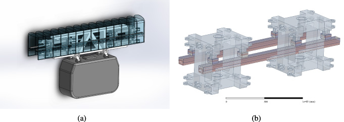
Model of suspended permanent magnet maglev train model. (a) Same scale model. (b) Simplified simulation model.
The arrangement of the track magnets of the permanent magnet maglev train adopts the Halbach array composed of three sets of permanent magnets, which are laid in the sky beam track plate and suspension frame. The Halbach array is a brand-new magnetic structure first proposed by Dr. K. Halbach from Lawrence Berkeley National Laboratory in 1980 [27,28]. The special structure of the Halbach array can effectively enhance the field intensity in the unit direction, and it has a good magnetic field self-shielding effect. Considering the application of the actual project, the Halbach array three-way arrangement is finally selected as the magnetic track arrangement for this project. It not only ensures the stability of the suspension operation of the carriage, but also reduces the number of magnets, reduces the weight of the train frame, and generates the required magnetic suspension force with the least number of magnets. Its structure is shown in Fig. 4.
Structural diagram of suspension permanent magnetic levitation rail transit system.
The permanent magnet is N45 magnet (Nd-Fe-45), and the array arrangement in the actual project is shown in Fig. 5. Combined with the actual construction project, the size of each permanent magnet is 100 ∗30 ∗30 mm in the simulation analysis.
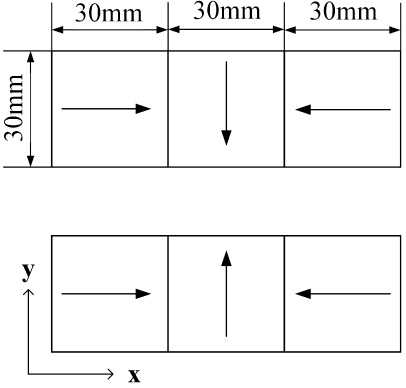
Halbach array arrangement.
In the ANSYS EM software static magnetic field solver, the calculation method used for the permanent magnet three-dimensional static magnetic field is the edge method [29]. That is, the calculation is based on the degree of freedom with the quantity on the edge of the subdivision unit, and the equivalent surface current or volume current method is usually used for the treatment of permanent magnets [30].
The basic Maxwell equations of the three-dimensional static magnetic field [31] are shown in Eq. ((1)).
The Maxwell equations [32] in the three-dimensional low-frequency transient field are shown in Eq. (3):
For permanent magnets, the magnetic induction intensity is as follows:
In the above formula, μ0 = 4π ×10−7 H∕m is the vacuum permeability, μ r is the relative permeability, and M p is the polarization strength of the permanent magnet material.
For the anisotropic magnetic materials, the three-dimensional static magnetic field is processed into a relative permeability tensor form:
The anisotropic calculation is realized by describing different relative permeabilities in three directions. The magnetic field intensity can be calculated by Eq. (6):
When solving, it is necessary to set the magnetic field boundary conditions [33], and select the first type of boundary conditions, that is, the Dirichlet boundary conditions,
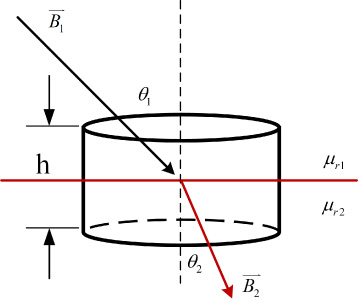
Boundary conditions of normal component of magnetic field.
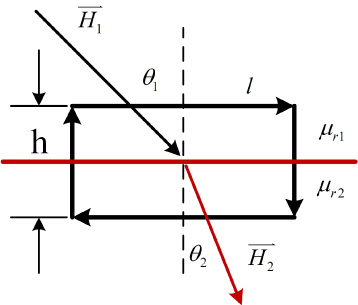
Where, the boundary condition of the normal component of the magnetic field (Fig. 6) is:
Where, the boundary condition of the magnetic field tangential component (Fig. 7) is:
In this paper, the finite element method is used to solve the magnetic field simulation. The finite element method is also called the matrix approximation method, is based on the variational principle and the weighted residual method. The basic idea is to simplify the solution domain of complex system problems into a large number of non-overlapping sub-domains of the finite interconnection. By solving the sub-domains, the approximate solution of the whole system is derived by using the variational principle or the weighted residual method. Through this method, the high-precision approximate calculation of the simulation model in this paper can be realized.
Boundary conditions of tangential component of magnetic field.
ANSYS simulation analysis
The static magnetic field solver is used to solve the magnetic radiation of the permanent magnet maglev rail transit system under static conditions. The whole simulation process considers the skin effect of the object, and meshing is performed by specifying the profile rule inside the model. The maximum side length of the unit is set to 10 mm. The solution domain selected is 20% to ensure the accuracy of the solution and improve the simulation efficiency. Table 1 presents the permanent magnet parameters.
Physical parameters of permanent magnet
Physical parameters of permanent magnet
In this paper, the finite element method is used to simulate the simplified suspension permanent magnet maglev rail transit model, and the magnetic field distribution is analyzed. The results are shown in Fig. 8. It shows that under the skin effect, the magnetic field intensity distribution is mainly concentrated on the track surface. The side edges of the magnets in the middle of the vehicle and track magnets are the most evident, and the magnetic field intensity inside is significantly greater than that outside. When the magnetic field strength is 1.64 T, the vehicle-mounted and orbital magnets have turned red locally, and the magnetic field strength approaches the maximum value, whereas the magnetic field strength of weakly magnetic and non-magnetic materials is substantially small compared with the permanent magnet and can be ignored. To further study the magnetic radiation of suspension permanent magnet maglev rail transit, we simulate the magnetic field intensity between single-point, four-point, and eight-point vehicle magnets and track magnets.

Magnetic field distribution of simplified model of permanent magnet maglev train. (a) Magnetic field distribution map. (b) Side magnetic field distribution map.
According to the actual engineering test line, in the simulation, the suspension height between the vehicle and the track magnet is set as 17 mm when the train is unloaded. Figure 9 shows the magnetic field distribution of the single-point magnet and the magnetic field distribution of the cross section of array magnet track.
Magnetic field intensity distribution of single-point magnetic group. (a) Cross-sectional magnetic field distribution of single point upper and lower magnets. (b) Cross-sectional magnetic field intensity of single-point suspension magnet. (c) Magnetic field distribution of single-point suspension magnet.
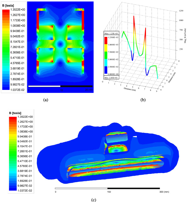
Figure 9 reveals that the magnetic field intensity between the single-point vehicle magnet and the orbiting magnet is concentrated on the contact surface between the permanent magnets in the middle of Halbach array, and the maximum magnetic field strength reaches 1.25 T. The magnetic field strength between the upper and lower magnets is evidently larger than the magnetic field strengths of the other parts, and the energy of the magnetic field is mostly concentrated on the side edges of the middle magnet between the vehicle and orbital magnets. The 45# steel, which is located on the side of the vehicle and track magnets, has good magnetic permeability. As a result, the magnetic field energy radiated by the magnetic field outward is small, and it has a complete closed-loop, meeting the magnetic flux density theorem, no magnetic leakage phenomenon occurs in the permanent magnetic suspension array magnet group.
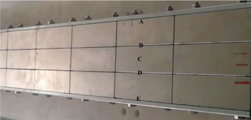
From the combination of the five sample points marked A, B, C, D, and E in Fig. 4, the magnetic field energy is distributed in two positions B and D, that is, the magnetic field intensity on both sides of the middle magnet of the vehicle and the track magnets are the highest. Table 2 shows the magnetic field intensity of the sample point.
Sample table of magnetic field intensity distribution
It can be seen from Fig. 9(b) that when the suspension height of the permanent magnet maglev train is 17 mm, the average magnetic field intensity of the vehicle body generated by the vehicle-mounted and orbital magnets is 0.44 T. The average magnetic field intensity is relatively high. According to the simulation results, it can be seen that the suspension module of the train itself has a complete closed-loop, which will not lead to magnetic field energy leakage.
Given that the suspended permanent magnet maglev train is affected by other factors during passenger loading or traveling, the suspension height is reduced, which will cause the magnetic field strength to change, and the magnetic field intensity is simulated when the suspension heights are 10, 13, and 15 mm. Figure 10 shows the results.

Magnetic field intensity at different suspension heights. (a) Magnetic field intensity with a suspension height of 10 mm. (b) Magnetic field intensity with a suspension height of 13 mm. (c) Magnetic field intensity with a suspension height of 15 mm. (d) Comparison of magnetic field intensity at different suspension heights.
According to Fig. 10, when the suspension height is 10 mm, the maximum magnetic field intensity between the permanent magnetic levitation arrays can reach 1.75 T; when the suspension height is 13 mm, the maximum magnetic field intensity between the permanent magnetic levitation arrays can reach 1.52 T; when the suspension height is 15 mm, the maximum magnetic field intensity between the permanent magnetic levitation arrays can reach 1.41 T. In order to see the variation of magnetic field more obviously, the magnetic field is compared when the suspension height of the permanent magnet maglev train is 10 mm, 13 mm, 15 mm, and 17 mm, as shown in Fig. 10(d). The comparison results show that the maximum energy values of the train’s body magnetic field are mainly distributed at 30 mm and 60 mm. When the train is fully loaded, the magnetic field intensity of the vehicle body is the largest. With the increase of suspension height, the magnetic field energy generated by vehicle-mounted magnet and orbital magnet decreases. In other word, affected by the suspension height, the magnetic field energy of the permanent magnet maglev train will change. With the increase of the suspension height of the permanent magnetic levitation train, the distance between the vehicle-mounted magnet and the orbital magnet increases, the magnetic field intensity between the track array magnets will attenuate. The magnetic field radiation of vehicle body generated by vehicle-mounted magnet and orbital magnet gradually weakens.
In order to study the dynamic magnetic field variation of the permanent magnet maglev train, the transient simulation analysis of single point magnet with a suspension height of 17 mm was carried out. The transient field solver is used to solve the magnetic radiation of the permanent magnet maglev rail transit system under transient conditions. The skin effect of the object is considered in the whole simulation process, and the meshing rules are specified in the model, and the maximum side length of the unit is set to 10 mm. In order to ensure the accuracy of the solution and improve the simulation efficiency, the solution domain is 500%, and the initial speed is 10 m/s and the running time is 20 ms. The simulation results are shown in Fig. 11.

Magnetic field distribution of single-point suspended magnet at different positions under transient state. (a) Magnetic field distribution at 0ms of single-point suspension magnet. (b) Magnetic field distribution at 4ms of single-point suspension magnet. (c) Magnetic field distribution at 8ms of single-point suspension magnet. (d) Magnetic field distribution at 12 ms of single-point suspension magnet. (e) Magnetic field distribution at 16 ms of single-point suspension magnet. (f) Magnetic field distribution at 20 ms of single-point suspension magnet.
Figure 11 shows that the maximum vehicle body magnetic field energy generated by the single-point suspension vehicle-mounted magnet and orbital magnet of the train under transient field is located at 30 mm and 60 mm of the track magnet. The position of the maximum vehicle body magnetic field energy corresponds to the above marked points B and D. Comparing (a), (c), (e), and (f) in Fig. 11, it can be clearly seen that when the train is moving, the position of the vehicle-mounted magnets moves with it. At the same time, the magnetic field energy of vehicle body generated by vehicle-mounted magnet and orbital magnet is also constantly changing, and the magnetic field intensity of vehicle body is also changing accordingly. The strong magnetic field changes of the vehicle magnetic field of the permanent magnet maglev train are the same under the transient field and the static field. The magnetic field energy of the magnetic track of the permanent magnet maglev train is mostly concentrated on the side edge of the magnet between the vehicle magnet and the track magnet. It can be seen that the 45# steel has good magnetic permeability, and the scattered magnetic field energy is very small. There is no magnetic leakage phenomenon in the array magnet group of the permanent magnet maglev train.
Through the aforementioned analysis, the magnetic field strength of a single-point suspension can be known. The following simulations are carried out for the four-point and eight-point suspensions to better understand the magnetic field intensity of the permanent magnet maglev train. The materials used are the same as the single-point suspension, and the suspension height is 17 mm. Figures 12 and 13 displays the simulation results.

Magnetic field intensity distribution of the four-point magnetic group.

Magnetic field intensity distribution of the eight-point magnetic group.
Analyzing Figs 12 and 13, the magnetic field distribution of the four-point and eight-point magnetic groups is uniform, respectively, and the magnetic field energy does not leak in the solution domain. Given the structural characteristics of the permanent magnet maglev train, the simulation results show that the magnetic field energy radiation range of the magnetic track is extremely small, and the support parts below the track magnet are not completely surrounded by the magnetic field. In addition, the magnetic energy generated by the floating module is shielded inside the track structure. Combined with the actual project size, the height of the track support is 60 mm, and the magnetic field of the permanent magnetic levitation array is mainly distributed in the area corresponding to the vehicle and the orbital magnets. The magnetic field strength in the other areas is significantly smaller than that in this area, and the magnetic field energy distribution is within the centimeter range. To better study the magnetic field intensity of the permanent magnet maglev train and explore the strong magnetic field distribution between the magnets in each group, this paper combines the sample points in Fig. 4 to select the midpoint of each group of magnets in the eight-point model to determine the corresponding path. In other words, the lower surface of the vehicle-mounted magnet is 50 mm away from the end face of the magnet as a path 1–8 with a length of 90 mm, as shown in Fig. 14.

Path1-path8 distribution map.
The magnetic field strength on the eight paths is studied, and Fig. 15 show the simulation results.
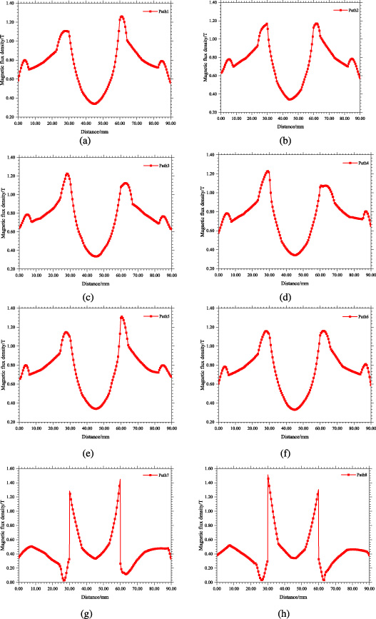
Magnetic field intensity distribution in different paths. (a) Magnetic field intensity distribution on path 1. (b) Magnetic field intensity distribution on path 2. (c) Magnetic field intensity distribution on path 3. (d) Magnetic field intensity distribution on path 4. (e) Magnetic field intensity distribution on path 5. (f) Magnetic field intensity distribution on path 6. (g) Magnetic field intensity distribution on path 7. (h) Magnetic field intensity distribution on path 8.
By comparing the magnetic field intensities of the eight paths in Fig. 15, the magnetic field energy of the array magnetic track is distributed in the B and D positions. Figure 15(a) shows that the maximum magnetic field intensity of path 1 is 1.26 T; Fig. 15(b) shows that the maximum magnetic field intensity of path 2 is 1.17 T; Fig. 15(c) shows that the maximum magnetic field intensity of path 3 is 1.23 T; Fig. 15(d) shows that the maximum magnetic field intensity of path 4 is 1.23 T; Fig. 15(e) shows that the maximum magnetic field intensity of path 5 is 1.32 T; Fig. 15(f) shows that the maximum magnetic field intensity of path 6 is 1.16 T; Fig. 15(g) shows that the maximum magnetic field intensity of path 7 is 1.45 T; Fig. 15(h) shows that the maximum magnetic field intensity of path 8 is 1.51 T. Affected by the Halbach permanent magnet array and the magnetizing direction of the permanent magnet, the magnetic field intensity of the suspension module is larger in the middle and smaller on both sides. The magnetic field intensity in the outer region of the track is almost zero, the maximum magnetic field intensity of the eight-point magnetic group can reach 1.51 T, and the minimum magnetic field intensity is 0.03 T. Based on the appeal results, the magnetic field intensity of the vehicle body generated by the vehicle-mounted and orbital magnets in each group of the permanent magnet maglev train is not the same. The maximum average vehicle magnetic field produced by the eight groups of suspension magnets of the train is 1.29 T. Through the above simulation results, the magnetic energy of the Halbach permanent magnet array is maintained within a centimeter-level space. Almost no magnetic leakage phenomenon occurs, and in the actual project of the suspended permanent magnet maglev train, the distance between the train car position and the suspension module is maintained at more than one meter, and the train is suspended on the column of 7.9m from the ground. The electromagnetic energy generated by the train has very small harm to the human body.
To verify the accuracy of the simulation, this paper uses a six-channel high-precision magnetic field test system to measure the magnetic field of the actual project of the permanent magnet maglev train under no-load. The six-channel high-precision magnetic field test system is shown in Fig. 16. The operation process is: (1) Install the experimental auxiliary tool fixing plate made of aluminum on the vehicle-mounted and orbital magnets of the train; (2) Assemble and open the six-channel high-precision magnetic field tester and connect to the computer; (3) Set the test channel, check and test whether the magnetic field sensor probe is normal; (4) Set the moving path of the probe to move along the direction of the end of the orbital magnet, and the moving range is 0–90 mm; (5) Zero and reset the readings; (6) Put on the magnetic field protective clothing, and place the sensor probe along the fixed plate to measure the magnetic field of the vehicle-mounted magnet and the orbital magnet, and save the data. (7) Process the measured data; (8) Arrange and analyze the measured results in combination with the sample points marked in Fig. 4. The results are shown in Table 3.
Sample collection data table of magnetic field intensity distribution
Sample collection data table of magnetic field intensity distribution

Six-channel high-precision magnetic field test system.
From the sample data in Table 3, the actual magnetic field intensity distribution law is consistent with the finite element simulation curve. The magnetic field energy is distributed at the positions B and D, and the magnetic field energy is larger in the middle and smaller on both sides, and the variation rang of the magnetic field intensity is large.
In this paper, the electromagnetic simulation of the suspension permanent magnet maglev rail transit system is carried out, and the single-point, four-point, and eight-point levitation magnetic groups of the permanent magnet maglev train are analyzed in detail, and the single point suspension magnetic groups of different suspension heights are analyzed. The following conclusions can be obtained:
The suspended permanent magnet magnetic levitation rail transit system can provide a good magnetic field shielding environment, hinder the leakage of magnetic field energy, and has a complete closed loop, can better meet the construction needs of permanent magnet maglev train project. With the increasing in the levitation height between the orbital and vehicle-mounted magnets, the generated magnetic field intensity exhibits a significantly weakening trend. In the future trial operation line, the levitation height can be increased while ensuring the normal operation of the train, the magnetic radiation can be reduced. The magnetic field energy of the permanent magnet maglev train is maintained at the centimeter level. In combination with the actual project, the distance between the position of the train car and the suspension module is maintained at more than 1 m, and the train is suspended on a column 7.9 m from the ground. Passengers on the train, pedestrians and residents along the Redrail will not be affected by the magnetic field intensity of the permanent magnet.
Footnotes
Acknowledgements
This work was supported by the Central Guided Local Science and Technology Funding Project of the Science and Technology Department of Jiangxi Province(Cross-regional Cooperation, 20221ZDH04052), the 03 Special Project and 5G Program of the Science and Technology Department of Jiangxi Province (No. 20193ABC03A058), the China Scholarship Council (CSC, No. 201708360150), the Key Foundation of Education Committee of Jiangxi (No. GJJ170493, No. GJJ190451), the Program of Qingjiang Excellent Young Talents in Jiangxi University of Science and Technology (JXUSTQJBJ2019004), and the cultivation project of the State Key Laboratory of Green Development and High-Value Utilization of Ionic Rare-Earth Resources in Jiangxi Province (20194AFD44003), the Key Research and Development Plan of Ganzhou (industrial field) the Science and Technology Innovation Talent Project of Ganzhou.