
Abstract
Compared with double-winding bearingless permanent magnet synchronous motor, single-winding bearingless permanent magnet synchronous motor (SBPMSM) has the advantages of low copper loss and low failure rate. However, if the slot-pole combination of SBPMSM is not reasonably selected, the winding coefficient will be reduced, and even many advantages of the single-winding structure will be offset. In this paper, a single-winding design method based on magnetomotive force (MMF) star diagram is proposed, which can ensure high winding coefficient. The design process of the proposed single winding structure is introduced. This method can match the appropriate number of stator slots according to the number of rotor poles, and the winding phase separation design can be realized by reversing the slot number transposition. The mathematical models of the suspension force and torque of the bearingless permanent magnet synchronous motor are derived considering the magnetic field harmonics, and the 6-slot/2-pole SBPMSM and 18-slot/8-pole SBPMSM are taken as examples to analyze the magnetic field. The finite element simulation models of 6-slot/2-pole SBPMSM and 18-slot/8-pole SBPMSM are built and analyzed. Through the analysis of electromagnetic torque, suspension force and air-gap magnetic field under different magnetic fields, the general rules of main torque fluctuation and suspension force fluctuation are summarized.
Keywords
Introduction
Compare with mechanical bearing permanent magnet synchronous motor, bearingless permanent magnet synchronous motor has the advantages of low noise, no mechanical friction, no pollution, no lubrication and sealing, long life, etc., even more compact than magnetic bearing motor [1]. Therefore, BPMSM is widely used in high-speed drive applications such as flywheel energy storage systems, turbo molecular pumps, and centrifugal compressors [2]. BPMSM is also suitable for special applications such as toxic and hazardous environments, sterile environments, and environments that require long-term operation and inconvenient maintenance [3,4].
The stator core of double windings BPMSM is embedded with two sets of windings, namely suspension winding and torque winding. The pole pairs of the two sets of windings differ by one. Through the interaction of two rotating magnetic fields with different pole pairs, the magnetic density in a certain direction of the original magnetic field is enhanced, then the suspension force required for the operation of the motor is generated [5]. However, the stator slot is embedded with two sets of windings exist shortcomings. On the one hand, the addition of interlayer insulation material reduces fill storage ratio and it is also not conducive to torque increase due to the suspension winding will occupy part of the stator slot space, thus limiting bearingless motor to a higher power density development. On the other hand, the use of two sets of windings will also increase the additional stator side copper loss and the complexity of motor design and production, so that the manufacturing costs have increased. Compared with the double-winding bearingless motor, single-winding bearingless permanent magnet synchronous motor (SBPMSM) avoids the inter-turn short circuit of the two sets of windings, can make full use of the space in the stator slot, and does not require a separate winding to provide suspension force. So SBPMSM has lower power loss, lower cost and higher reliability [6,7]. Therefore, SBPMSM has attracted more and more attention from scholars at home and abroad.
In [8], a single-winding bearingless motor with split-phase structure was proposed. One phase of the four-pole two-phase winding is split into four parts. The interaction between the four split windings and the other phase winding caused the rotor to suspend, but the control performance of this structure is poor. In [9], a bridge winding structure was proposed. Each phase of the winding is divided into two parallel paths, and the midpoints of the two branches are connected to an inverter that controls the suspension force current. By increasing the current on one side and weakening the current on the other side in each phase winding, the uneven distribution of the magnetic field is formed to achieve rotor suspension. In [10–12], the multi-phase single-winding structure was proposed. The rotor rotation and suspension are realized by using the characteristics of five-phase and above winding magnetic field with multiple control degrees of freedom. In [13], a 4-pole 6-slot single-winding six-phase bearingless permanent magnet slice motor was proposed. Each tooth winding is regarded as a phase and each phase is controlled by an independent H-bridge circuit. In [14], a middle-point-current-injection-type winding was proposed to achieve asymmetric distribution of air-gap flux density by injecting additional suspension force current at the midpoint of each phase winding. Compared with double-winding BPMSM, the suspension force is smaller, on account of this way of suspension just change the air gap flux density in one side. In [15], the SBPMSM has achieved an ultra-high speed of 150000 r/min because of the stator slotless structure was adopted based on the SBPMSM of current component superposition. The slotless stator can reduce the air-gap magnetic field harmonics and reduce the loss under high speed rotation of the motor. Based on the single-phase theory, a SBPMSM with 3 pole pairs of torque magnetic field and 2 pole pairs of suspension magnetic field is designed in [16], only three concentrated windings are wound in six stator slots. In [17], a four-phase SBPMSM was proposed, which realized rotor suspension by using winding misalignment distribution.
In this paper, a winding design method of SBPMSM with slot-pole combination of 2P m + 2P s = Z is proposed. By deriving the mathematical model of suspension force and torque of SBPMSM with harmonic distribution of air-gap magnetic field, and according to the torque fluctuation and suspension force fluctuation of the motor, the main air-gap flux density harmonics causing torque fluctuation and suspension force fluctuation are determined, and the general conclusion suitable for the proposed SBPMSM is obtained, which provides a reference for the design and optimization of bearingless motor. On this basis, the 6-slot/2-pole SBPMSM and 18-slot/8-pole SBPMSM are simulated by Ansys Maxwell to verify the correctness of the model and the conclusion.
Winding design idea of SBPMSM
Suspension principle of SBPMSM
For bearingless permanent magnet synchronous motor, whether it is single winding structure or double winding structure, the suspension force is generated by introducing the magnetic field generated by suspension current to change the magnetic field distribution in the motor and make the magnetic density of the original magnetic field in a certain direction. Therefore, the principle of SBPMSM producing suspension force is the same as the traditional double-winding BPMSM. To achieve stable suspension of the rotor, the following relationship needs to be satisfied between the two magnetic fields [18,19].
(a) The difference between the pole pair of torque magnetic field (P m ) and the pole pair of suspension magnetic field (P s ) is one, that is, P m = P s ± 1.
(b) The rotation direction and electric angular velocity of torque magnetic field are the same as those of suspension magnetic field.
The interaction between rotating magnetic fields makes there are two different types of BPMSM, respectively are the Maxwell force and the Lorentz force. The Maxwell force is the main component of suspension force, which is caused by the interaction of the radial magnetic field generated by the suspension winding and the permanent magnet. It is different from the traditional permanent magnet synchronous motor, there is not only tangential Lorentz force in the motor, but also radial Lorentz force whose direction is perpendicular to the rotor surface.
Figure 1(a) shows the positive X-axis suspension force, in the air gap on the left side of the motor, the polarity of the magnetic field of the permanent magnet is opposite to the magnetic field generated by the current of the suspension force winding, the synthetic magnetic field on the left side will be weakened. In the air gap on the right side of the motor, the polarity of the magnetic field of the permanent magnet and the magnetic field generated by the suspension force winding current are the same, then the synthetic magnetic field on the right side will be enhanced. Since the direction of the Maxwell force is from the lower magnetic density to the higher magnetic density, the electric machine will generate the Maxwell force to the right. Figure 1(b) shows the magnetic field line distribution diagram of bearingless permanent magnet synchronous motor, from which it can be seen that the magnetic field line density in the positive direction of x axis increases, while the magnetic field line density in the negative direction of x axis decreases.

Suspension mechanism of BPMSM. (a) Principle of suspension generation. (b) Distribution of magnetic field lines.
To sum up, in BPMSM, the tangential Lorentz forces produces the electromagnetic torque that rotates the motor, and the suspension force produced in bearingless permanent magnet synchronous motor is the vector superposition of Maxwell force and radial Lorentz force. When the rotor is not offset, the motor can run smoothly, and the radial suspension force generated by the suspension force current only needs to overcome the rotor gravity. When the rotor is eccentric, the suspension force generated by the suspension force current applied at this time needs to overcome the Maxwell force caused by the rotor eccentricity, so that the rotor returns to the center position.
In the design process of single-winding bearingless motor, in addition to considering the torque performance, it is also necessary to take into account the suspension performance. The winding coefficient is an important parameter to measure the quality of the winding. It is necessary to ensure that the torque winding coefficient and the suspension force winding coefficient are as high as possible in the design process.
For the winding coefficient of the v-th MMF harmonic, its value is equal to the product of the short-distance coefficient k
yv
and the distribution coefficient k
qv
of the v-th MMF harmonic, that is,
For the winding whose phase belt is 2 times of the phase number, when the sum of the slot pitch angle of the two sets of windings is 180°, the winding wiring of the two sets of windings in the stator slot can be exactly the same. For the realization of SBPMSM, there is a formula:
The slot pitch angle 𝛼 is the mechanical angle between adjacent stator slots, the value is 360°∕Z and Z is the number of stator slots. So, (4) can be transformed into
This rule provides a new idea for the realization of SBPMSM. Based on the idea of current component superposition, two current components are injected into a set of windings to generate two rotating magnetic fields to realize the suspension of the rotor, it ensures that the torque winding and the suspension force winding have high winding coefficient. Taking the commonly used three-phase motor as an example and considering that the number of stator slots is generally a multiple of 3, on the basis of (5), the slot-pole combination satisfying SBPMSM with high winding coefficient can be obtained and the results are shown in Table 1.
Slot-pole combinations of SBPMSM
It can be seen from Table 1 that torque magnetic field and suspension magnetic field of the motor can maintain a high winding coefficient, and the winding combination of the two magnetic fields are the same. In the design process, the number of stator slots can be quickly matched according to the number of rotor poles. The above slot-pole combination is obtained on the basis of three-phase windings. For other phase windings, different slot-pole combination can still be obtained according to 2P m + 2P s = Z, which is not listed here.
This section takes P m = 1, P s = 2, Z = 6 and P m = 4, P s = 5, Z = 18 as examples to describe the winding design principle of this single winding structure in detail.
Firstly, the MMF star diagrams of the three-phase 60° phase with winding of 6-slot/2-pole (6s/2p) and 6-slot/4-pole (6s/4p) are drawn, as shown in Fig. 2.
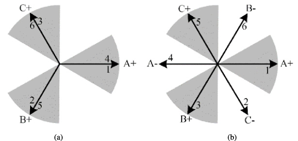
6s/2p and 6s/4p MMF star diagrams: (a) 6s/2p. (b) 6s/4p.
It can be seen from Fig. 2 that the MMF star diagram is divided into six phase bands, each phase band occupies a 60° mechanical angle and each phase of the winding is divided into two phase bands. The A, B, and C phase bands are marked as A+, B+ and C+, and the X, Y, and Z phase bands are marked as A-, B-, and C-. By comparing Fig. 2(a) and Fig. 2(b), it can be seen that the slot number distribution under the same phase band of 6s/2p and 6s/4p is not the same. For example, the B phase in Fig. 2(a) is 3 and 6 slots, but the 2 and 5 slots in Fig. 2(b) are allocated under the B phase, so the conventional winding arrangement cannot achieve the single winding structure.
However, if changing the arrangement direction of the MMF star diagram of one of 6s/2p or 6s/4p, thereby changing the slot number distribution under each phase band. Thus, the same slot number under each phase can be realized, thereby realizing a single winding structure. By changing the arrangement direction of the 6s/4p slot star diagram, the MMF star diagram of 6s/2p and 6s/4p is arranged in the opposite direction. At present, the phase corresponding to each slot number of 6s/2p and 6s/4p is exactly the same, only the phase band is different. Changing the arrangement direction of the slot MMF star diagram and each slot phase comparison are shown in Fig. 3 and Table 2.
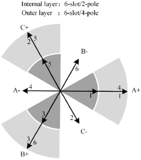
MMF star diagram after changing slot number of 6s/2p and 6s/4p structure.
The winding phase distribution of 6s/2p and 6s/4p after changing the arrangement direction of MMF star diagram
According to the winding arrangement in Fig. 3 and Table 2, two sets of current components can be simultaneously input on a set of windings to generate two rotating magnetic fields, which correspond to suspension magnetic field and torque magnetic field in BPMSM. Since the MMF star diagram of 6s/4p structure is opposite to that of 6s/2p structure, the direction of magnetic field rotation is opposite to that of 6s/2p when the same current is applied. In order to make the two magnetic fields rotate in the same direction, it is necessary to change the phase sequence of the three-phase alternating current to exchange the B and C phase current. Considering that the phase bands of the windings of 6s/2p and 6s/4p structures are different under the same phase distribution, the two sets of current component vectors are superimposed when the phase bands are the same, and the two sets of current component vectors are subtracted when the phase bands are different. The original phase is divided into two phases according to the same phase band and different phase band, the slot number with the same phase band is classified into A1, B1 and C1 phases, and the slot number with different phase band is classified into A2, B2 and C2 phases. At this time, the single winding structure has six input terminals, and the input current is as follows:
Since the stator current is no longer the traditional three-phase relationship, this paper uses an H-bridge circuit to control each winding input. Figure 4 shows the SBPMSM power system topology. The electromagnetic torque and suspension force are generated by controlling the current in the six H-bridge respectively.
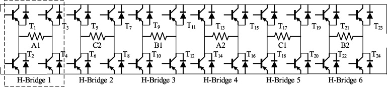
Power system of SBPMSM.
Similarly, for the 18-slot /8-pole (18s/8p) and the 18-slot /10-pole (18s/10p), the MMF star diagrams of the three-phase 60° phase-band of 18s/8p and 18s/10p are drawn, as shown in Fig. 5.
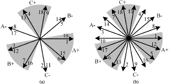
MMF star diagrams of 18s/8p and 18s/10p: (a) 18s/8p. (b) 18s/10p.
By comparing Fig. 5(a) and Fig. 5(b), it can be seen that the slot distribution under the same phase band is not the same. For example, there are 1, 6, 8, 10, 15 and 17 slots under phase A in Fig. 5(a), but in Fig. 5(b), 6, 8, 15 and 17 slots are distributed under phase B. It is obvious that the conventional winding arrangement cannot achieve a single winding structure.
However, if the position of initial slot of one set of windings is changed, by rotating 180° on the MMF star diagram and changing the rotation direction of slot number distribution, the single-winding structure will be realized. For example, the initial slot number of the 18s/10p MMF star diagram is changed, make it rotated 180° and sorte backward. By this time, the original 10th slot is at the current 1st slot position and the phase corresponding to each slot of the 18s/8p and 18s/10p structures is exactly the same. 18s/8p and 18s/10p structure after changing the slot number slot MMF star diagram and each slot phase comparison are shown in Fig. 6 and Table 3.

MMF star diagram after changing slot number of 18s/8p and 18s/10p.
The winding phase distribution of 18s/8p and 18s/10p after changing the arrangement direction of MMF star diagram
According to the winding arrangement in Fig. 6 and Table 3, two sets of current components can also be input on a set of windings to generate two rotating magnetic fields. In order to make the two magnetic fields rotate in the same direction, the phase sequence of the three phase alternating current needs to be changed. Similarly, the same phase is divided into two phases according to whether the phase band is the same. At this time, the single winding is the six-phase structure, and the expression of the input current is the same as that of formula (6).
For other slot-pole combinations that meet the law of 2P m + 2P s = Z, there is still the same winding law. SBPMSM can be realized by changing the rotation direction of the MMF star diagram of one of the pole pairs.
The SBPMSM proposed in this paper is a fractional slot motor, The fractional slot motor can further reduce the stator copper loss due to the short end winding, but its magnetic field harmonic content is more abundant than that of the integer slot motor. When the motor is an integer slot structure, the harmonic number of the air-gap flux density is an integer multiple of the pole pairs. When the motor is fractional slot structure, the air-gap flux density harmonics is not integer times the number of pole pairs, but contain other harmonics, which make the magnetic field distribution more complex. Therefore, the harmonic analysis of the proposed SBPMSM is particularly important.
Firstly, the mathematical model of BPMSM is assumed as follows:
(a) Ignore magnetic saturation and magnetic flux leakage.
(b) Ignore the motor end effect.
(c) Ignore the magnetic potential of ferromagnetic material.
(d) The rotor is located in the center.
Air-gap magnetic field analysis of SBPMSM
The air-gap magnetic field in SBPMSM is composed of the magnetic field produced by permanent magnet (PM), the magnetic field produced by suspension winding and the magnetic field produced by torque winding.
The expression of radial air-gap magnetic density is
The MMF generated by the PM can be expressed as
The MMF generated by the torque winding can be expressed as
The MMF generated by the suspension winding can be expressed as
When the stator is slotted, the air-gap magnetic permeance can be expressed as
Substituting (8)–(11) into (7), the expression of air-gap flux density is
The number of harmonics of the magnetic field generated by the winding can be summarized as follows: when the winding is an integer slot, the harmonic frequency is (6t ±1) p; when the winding is a fractional slot and the number of slots per pole per phase is b + c∕d (c/d is the simplest fraction), when d is odd, the harmonic number is p (6t +1)∕d, when d is even, the harmonic number is 2p (3t +1)∕d, where t = 0, ±1, ±2, ±3…; p is the number of pole pairs of the winding [20].
In order to facilitate the analysis of the proposed SBPMSM, (12) can be transformed into the superposition of 10 components, namely
In (13), B a , B b and B c are formed by the interaction between the constant components of the MMF without considering the slotting and the constant component of air-gap magnetic permeance. B d and B e are formed by the interaction between the tooth harmonic of the winding MMF and the constant components of air-gap magnetic permeance. B f , B g and B h are formed by the interaction between the MMF without considering the slotting and the harmonic component of the air-gap magnetic permeance. B i and B j are the tooth harmonic of the winding MMF and the harmonic component of air-gap magnetic permeance. The amplitude of B i , B j is very small and can be ignored. B g and B h are the same as B d and B e in number, which can be called the tooth harmonic of the winding magnetic field. The ten terms of B a -B j can be expressed by B r (𝜃, t) = Bcos(q𝜔t −𝜆𝜃 + 𝜑), q represents the time harmonic order, and 𝜆 represents the space harmonic order. The air-gap magnetic field distribution of SBPMSM is shown in Table 4.
Air-gap magnetic field distribution of SBPMSM
The 6s/2p SBPMSM and 18s/8p SBPMSM are taken as examples to analyze the specific magnetic field harmonics, as shown in Table 5 where, ‘−’ indicates the rotation direction opposite to the fundamental harmonic, and the angular velocity of each harmonic is reflected in brackets. The harmonic analysis of air-gap magnetic field in this section is helpful to clarify the source of harmonics, which can eliminate some harmonics in motor optimization. It can also be seen from Table 5 that the same harmonics in the air-gap magnetic field have multiple sources, and the rotation direction and angular velocity may also be different.
Magnetic field harmonic distribution of 6s/2p and 18s/8p SBPMSM
Maxwell force is the magnetic tensile stress generated by the magnetic field at the boundary of materials with different permeability (such as air and iron core), which is the main component of the suspension force.
According to the Maxwell tensor method, the Maxwell force per unit area can be obtained [21]:
The suspension forces F
x
and F
y
acting on the rotor surface in the x-axis and y-axis directions are
Substituting the (13) into the (15) and (16), the expressions of the suspension forces F
x
and F
y
of the rotor surface pointing to the x-axis and y-axis can be obtained by the integration and difference of trigonometric functions.
(17) and (18) are the suspension force calculation models considering the air-gap magnetic field harmonics. They can be used to analyze the air-gap flux density source which cause the suspension force fluctuation and calculate the influence of the interaction air-gap flux density harmonics on the suspension force. From (17) and (18), it can be concluded that the suspension force is not 0 only when the number of space harmonics of the interaction is different from 1. In which, when the two harmonics rotation directions are the same and the frequencies are equal, a constant suspension force component will be generated, otherwise the suspension force will fluctuate.
The 6s/2p SBPMSM and 18s/8p SBPMSM are used to analyze the specific suspension force, as shown in Table 6. The ‘−’ indicates that the rotation direction of the fundamental wave is opposite, and the brackets reflect the angular velocity and source of each harmonic.
Suspension force harmonic component of 6s/2p and 18s/8p SBPMSM
It can be seen from Table 6 that the magnetic field harmonics of PM will not interact to produce suspension force fluctuations, that is, there is no unbalanced magnetic pull (UMP). The frequency of the suspension force generated by the interaction between torque magnetic field harmonics and PM magnetic field harmonics is 0. The interaction between suspension magnetic field harmonics and PM magnetic field harmonics produces suspension force fluctuations of multiple frequencies.
The torque of SBPMSM is generated by the interaction of stator and rotor magnetic fields. The energy storage of air-gap magnetic field in motor is
According to the energy method, the torque can be obtained by calculating the partial derivative of the relative position of two harmonics 𝜑 in (19).
Substituting (13) into (20), the expression of torque can be obtained:
Equation (21) is the torque calculation model considering the air-gap magnetic field harmonics established. It can be seen that when the space between the two harmonics is the same, the torque will not be 0. In which, when the two harmonics rotate in the same direction and have the same frequency, a constant torque component is generated, otherwise the torque fluctuation is generated.
The specific torque analysis is also performed on the 6s/2p SBPMSM and the 18s/8p SBPMSM, as shown in Table 7.
Torque harmonic component of 6s/2p and 18s/8p SBPMSM
It can be seen from Table 7 that the suspension magnetic field harmonics of the 6s/2p SBPMSM and the 18s/8p SBPMSM will not affect the torque. But the interaction between torque magnetic field harmonics and PM magnetic field harmonics will produce 6th, 12th torque fluctuations.
Through the analysis of the suspension force and torque of the two slot-pole combination SBPMSM, it can be concluded that for the SBPMSM with 2P m + 2P s = Z slot-pole combination, the frequency of suspension force generated by the interaction between torque magnetic field harmonics and suspension magnetic field harmonics is 0, it will not affect the amplitude of fluctuation of suspension force but will affect the direction of suspension force. This means the magnetic field of the suspension force will not affect the torque.
In this section, 6s/2p and 18s/8p SBPMSM are taken as examples. Then by simulating proposed SBPMSM with the finite element analysis software Ansys Maxwell to verify the correctness of the structure, and the air-gap magnetic field harmonics are analyzed in detail. The simulation diagram and specific simulation model parameters are shown in Fig. 7 and Table 8.

Simulation plane diagram of 2p/6s SBPMSM and 18s/8p SBPMSM: (a) 6s/2p SBPMSM. (b) 18s/8p SBPMSM.
Simulation model parameters of 6s/2p and 18s/8p SBPMSM
In order to avoid the influence of magnetic saturation of silicon steel sheet on the analysis, the material is set to infinite permeability. For 6s/2p SBPMSM, the FEA verification of the interaction between PM magnetic field, torque magnetic field and suspension magnetic field is carried out. The simulation results of suspension force of 6s/2p SBPMSM are shown in Fig. 8. It can be seen that the SBPMSM can produce suspension force in a constant direction, which verifies the feasibility of the single winding structure. Figure 8(a)–(c) study the influence of the presence or absence of torque magnetic field on the suspension force when PM magnetic field and suspension magnetic field are fixed. It can be seen that the torque magnetic field will affect the amplitude of the suspension force in the x and y directions but has little effect on the amplitude of the synthetic suspension force. That means torque magnetic field affects the direction of suspension force and has little effect on the magnitude and waveform of the synthetic suspension force. This verifies the conclusion obtained in the previous section that torque magnetic field harmonics will basically not affect the amplitude of fluctuation of the suspension force fluctuation, but will affect the direction of the suspension force.
By setting the PM material to vacuum and simulating the suspension force generated by the interaction between torque magnetic field and suspension magnetic field, the results were shown in Fig. 8(d). It can be seen that the suspension force generated by the interaction between torque magnetic field and suspension magnetic field is almost constant amplitude, and the direction is different from that of the suspension force generated by the interaction between PM magnetic field and suspension magnetic field, which further verifies the correctness of the conclusion.

Suspension force waveform of 6s/2p SBPMSM: (a) Synthetic suspension force waveform. (b) Suspension force waveform of x direction. (c) Suspension force waveform of y direction. (d) Suspension force waveform without PM.
The Fast Fourier Transformation (FFT) of suspension force waveform with three magnetic fields is shown in Fig. 9. It can be seen that the suspension force mainly has 2nd, 4th, 6th and other times fluctuation, and the amplitude of 4th fluctuation is larger. Combined with Table 6, the interaction between the 3(3P m )rd harmonic of PM magnetic field and the 2nd tooth harmonic of suspension magnetic field causes the 2nd fluctuation of the suspension force. The interaction between the 3(3P m )rd harmonics of PM magnetic field and the 4(Z-P s )th tooth harmonic of suspension magnetic field causes the 4th fluctuation of suspension force. The 6th fluctuation of the suspension force has multiple fluctuation sources, which are generated by the interaction of the 1st tooth harmonic of PM magnetic field and the 2nd tooth harmonic of suspension magnetic field, the 5th harmonic of PM magnetic field and the 4th tooth harmonic of suspension magnetic field, the 7th harmonic of PM magnetic field and the 8th tooth harmonic of suspension magnetic field.
FFT diagram of suspension force of 6s/2p SBPMSM.
Figure 10(a) shows the torque waveform of the presence or absence of suspension magnetic field when PM magnetic field and torque magnetic field are fixed. Figure 10(b) shows the torque waveform diagram generated by the interaction only between torque magnetic field and suspension magnetic field after setting the PM material to vacuum. It can be clearly seen that the introduction of the suspension force current has no effect on the torque from Fig. 10(a) and the interaction between torque magnetic field and suspension magnetic field will not produce torque from Fig. 10(b). That verifies the suspension magnetic field will not affect the torque.

Torque waveform of 6s/2p SBPMSM: (a) Torque waveform with or without suspension force current (b). Torque waveform without PM.
The torque waveform of 18s/8p SBPMSM is analyzed by FFT, and the FFT diagram is shown in Fig. 11. It can be seen that the torque mainly contains 6th and 12th fluctuations, the other fluctuations are too small to be ignored. The constant component of torque is mainly produced by the interaction between the fundamental harmonic of PM magnetic field and the fundamental harmonic of torque magnetic field. Combined with Table 7, the 6th fluctuation of torque has multiple sources. However, the related PM magnetic field harmonics are related to the PM 5(5P m )th and 7(7P m ) th MMF harmonics. Because of the large amplitude of 5th and 7th harmonic, the 6th fluctuation of torque is mainly caused by the interaction between 5th and 7th harmonic of torque magnetic field and 5th and 7th harmonic of PM magnetic field. Similarly, the 12th fluctuation of torque mainly by interaction between 11(11P m )th harmonic of PM magnetic field and 11(11P m )th harmonic of torque magnetic field, 13(13P m )th harmonic of PM magnetic field and 13(13P m )th harmonic of torque magnetic field.

FFT diagram of torque of 6s/2p SBPMSM.
Similarly, the suspension force of 18s/8p SBPMSM is analyzed, as shown in Fig. 12.

Suspension force waveform of 18s/8p SBPMSM: (a) Synthetic suspension force waveform. (b) Suspension force waveform of x direction. (c) Suspension force waveform of y direction. (d) Suspension force waveform without PM.
It can also be concluded that the same as 6s/2p SBPMSM: torque magnetic field affects the direction of suspension force, but has little effect on the amplitude and waveform of synthetic suspension force.
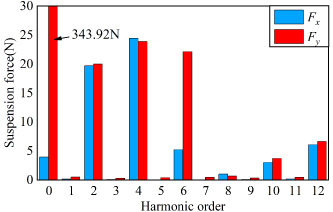
The FFT diagram of suspension force waveform with three magnetic fields is shown in Fig. 13.

FFT diagram of suspension force of 18s/8p SBPMSM.
It can be seen that the suspension force mainly has 2nd, 4th and 6th fluctuations, and the 4th fluctuations of the suspension force are still the largest. Combined with Table 6, the interaction between the 12(3P m )th harmonics of PM magnetic field and the 11th harmonic of suspension magnetic field causes the 2nd fluctuation of suspension force. The interaction between the 12(3P m )th harmonic of PM magnetic field and the 13(Z-P s )th harmonic of suspension magnetic field causes the 4th fluctuation of suspension force. The 6th fluctuation of suspension force also has multiple fluctuation sources, which are generated by the interaction of the 2nd tooth harmonic of PM magnetic field and the 1st tooth harmonic of suspension magnetic field and the 10th harmonic of PM magnetic field and the 11th tooth harmonic of suspension magnetic field.
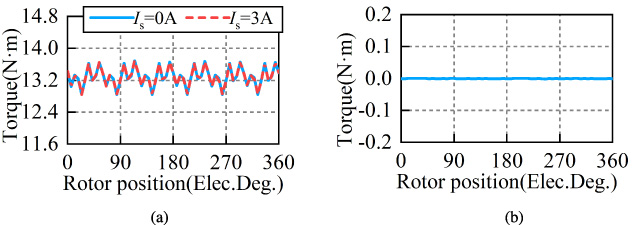
Torque waveform of 18s/8p SBPMSM: (a) Torque waveform with or without suspension force current. (b) Torque waveform without PM.
For the torque of 18s/8p SBPMSM, it can also be seen from the Fig. 14 that suspension magnetic field has no effect on torque. The torque waveform is analyzed by FFT and the FFT diagram is shown in Fig. 15. It can be clearly seen that the torque mainly contains 6th and 12th fluctuations, and the other fluctuations are too small to be ignored. Combined with Table 7, the same conclusion can be drawn as that of 6s/2p SBPMSM.

Torque FFT diagram of 18s/8p SBPMSM.
Through all above analysis, the following conclusions can be summarized: For the SBPMSM with 2P m + 2P s = Z slot-pole combination, in one electric cycle, the suspension force fluctuation is mainly the 4th fluctuation caused by the interaction between the (Z-P s )th tooth harmonic of suspension magnetic field and the (3P m )th harmonic of PM magnetic field. The torque fluctuation is mainly composed of two parts, one is the 6th produce by the fluctuation of (5P m )th and (7P m )th harmonics of PM magnetic field and the harmonic of same order in torque magnetic field, the other is 12th fluctuation, which produce by the interaction of and (11P m )th and (13P m )th harmonics of PM magnetic field and the harmonics of same order in torque magnetic field.
In this paper, firstly, a single winding arrangement for bearingless motors satisfying 2P m + 2P s = Z slot-pole matching is proposed, which has a high winding coefficient, and the principle is described based on MMF star diagram. Secondly, the suspension force mathematical model and torque mathematical model considering the cogging effect and the magnetic field harmonic distribution are derived, which can effectively locate the harmonic source causing the suspension force fluctuation and torque fluctuation. By analyzing the suspension force fluctuation and torque fluctuation of the proposed SBPMSM, the general conclusion of causing the suspension force fluctuation and torque fluctuation is obtained. Finally, the correctness of the proposed winding structure and conclusion is verified by finite element simulation. For the SBPMSM with 2P m + 2P s = Z slot-pole combination, the conclusions are as follows:
(a) The torque magnetic field will not affect the amplitude of fluctuation of suspension force, but will affect the direction of suspension force. suspension magnetic field has little effect on torque.
(b) The main source of suspension force fluctuation is the 4th fluctuation generated by the interaction between the (3P m )th harmonic of PM magnetic field and the (Z-P s )th harmonic of suspension magnetic field due to the cogging effect.
(c) The same as the traditional PMSM, the main source of torque fluctuation is the (5P m )th and (7P m )th harmonics of PM magnetic field interact with the harmonic of same order of torque magnetic field to produce 6th torque fluctuation, the (11P m )th and (13P m )th harmonics of PM magnetic field interact with the harmonic of same order of torque magnetic field to produce 12th torque fluctuation.
The analysis and conclusions of this paper provide theoretical support for the realization of SBPMSM, and provide reference for the design and optimization of SBPMSM.
Footnotes
Acknowledgement
This work was supported in part by the project supported by the National Natural Science Foundation of China (52277064) and Zhejiang Provincial Natural Science Foundation of China (LY22E070005).