
Abstract
Due to the large amount of finite element calculation resources, the calculation stability is low. In order to obtain accurate torque data conveniently, a new torque modeling method is proposed in this paper. By establishing the minimum torque model, the finite element software is used to obtain elementary torque map, and the torque within the whole rotor motion range is built by polynomial fitting, and then the position torque in the process of rotor motion under different currents is obtained by multiple linear interpolation method, and converted to the global coordinate system by projection. The multicoil torque is superimposed and corrected by using the dynamic error coefficient to obtain the final synthetic torque. Finally, the effectiveness of the modeling method is verified by simulation and experiments. The results show that this method not only ensures the modeling accuracy, but also speeds up the calculation.
Keywords
Introduction
With the advancement of science and technology and the development of society, the manipulator and robot industries are gradually rising [1]. The traditional single-degree-of-freedom operation of motor no longer meets the needs of industry and life. Although the traditional motor can meet the multi-degree-of-freedom operation through multiple traditional motors, this situation will lead to a bulky system, high control requirements, mutual errors and other problems.
In order to better meet the needs of multi-degree-of-freedom operation, scholars worldwide began to study spherical motors for a long time, and put forward a variety of spherical motor structures from the earliest developed magnetoresistive stepping spherical motor to induction spherical motor, permanent magnet spherical motor, Halbach array spherical motor and magnetoresistive spherical motor [2,3]. Compared with traditional motors, these spherical motors can complete the operation of multiple degrees of freedom by one motor, which greatly simplifies the mechanical structure and reduces the manufacturing cost [4]. So far, more and more scholars have begun to study spherical motors.
Due to the strong coupling electromagnetic structure and good performance of spherical motor, the diversity of three-dimensional motion, the size and direction of electromagnetic force are different, and the time and position of each magnetic pole are different. Therefore, it is difficult to analyze the magnetic field and the torque of the motor. Generally, the finite element method is used for global analysis [5,6]. The development of permanent magnet motor is very early and fast, the reason is that there is no iron core material added to the spherical motor, which is linear. So far, the modeling methods of permanent magnet spherical motor include: fitting modeling of permanent magnet spherical motor with finite element software [7,8], three-dimensional magnetic field modeling based on spherical harmonic function and Laplace equation [9], modeling based on surface current model and Lorentz force method [10], etc.
The research of reluctance spherical motor involves the fields of electromotor, microelectronics and power electronics. In addition, its nonlinear characteristics increase the difficulty of research. However, with the progress of science and technology, scholars have also made great progress in the research of reluctance spherical motor. Lee and others designed a double excitation two degree of freedom reluctance spherical motor for surveillance camera [11], and analyzed the static torque characteristics by using the equivalent magnetic circuit method [12]. Zeng designed a spherical switched reluctance magnetic levitation motor based on the magnetic levitation theory and the principle of minimum reluctance, derived the magnetic permeability of the gap by using the magnetic segmentation method, and obtained the mathematical model of the spherical motor [13], through the established three-dimensional coordinate system, a rotor position detection method based on radial displacement sensor and angular displacement sensor is proposed [14]. In recent years, Ju proposed a three-degree-of-freedom spherical reluctance motor, established the basic mathematical model of the spherical motor according to the electromagnetic law and energy conversion principle, analyzed the motor by three-dimensional finite element method, and obtained the characteristics of magnetic field distribution and static torque during spin and pitch [15,16]. Later, Qiao based on the finite element software, the virtual displacement method was used to model the motor and establish the inductance curve and moment angle characteristics of the motor [17]. Recently, Xu proposed a sensorless rotor posture detection method based on the mutual inductance voltage of the stator coil to simplify the position detection element of a reluctance spherical motor. This method is based on the real-time voltage generated by stator coil mutual inductance, combined with motor structure constraints and intelligent algorithm to reverse the three-degree-of-freedom position angle [18].
Due to the complex magnetic field distribution in RSM and its nonlinear characteristics, it is very difficult to calculate by the analytical method, and the error after numerical differentiation is very large, so it is difficult to establish a correct model. Therefore, in order to quickly obtain an accurate torque model, modeling based on the finite element method is feasible. In this paper, the elementary model of torque is used for finite element calculation, which reduces the model calculation to the area corresponding to a single stator coil and rotor, which greatly shortens the calculation time, and can quickly calculate the torque of a single coil under the condition of withstanding current. Then, the torque in the range of rotor spin and pitch motion is built by polynomial fitting, and the torque value of each position in the process of rotor motion under single coil can be calculated by the interpolation method. The torque in the spin or pitch motion under the single coil is projected into the global coordinate system, and the dynamic error coefficient is calculated according to several important positions between the rotor and stator coil, which is fitted by binary polynomial. Finally, based on the dynamic error coefficient and multicoil torque, the synthetic torque is obtained.
Structure and coordinate system division
Spherical motor structure
The main parts of the motor include stator spherical shell, rotor body, coil, iron core and output shaft. The basic structure of the spherical motor is shown in Fig. 1. In order to facilitate multi-degree-of-freedom motion, the stator shell and rotor shell are designed as spherical. The rotor is divided into six poles, with an interval of 60° between two adjacent magnetic poles. The rotor is pressed by silicon steel sheet. The surface of the rotor is an arc surface in the shape of a salient pole. The stator core and housing are made of DT4 material. There are 24 energizing coils in total, which are centrally distributed and divided into three layers, with a difference of 33° for each layer. The middle layer coil is located on the equatorial plane, and the other two layers are evenly distributed on both sides of the equator, with an interval of 45° between adjacent coils on the same layer. A pole shoe is added at the end of the stator core, which is wider than the stator core. See Table 1 for the detailed data of the motor.

Structure diagram of the RSM.
Main parameters of the RSM
The operation principle of the motor is similar to that of the traditional switched reluctance motor. The motor can rotate around the Z-axis by changing the power of the adjacent coils on the same layer; When the adjacent coils of the upper and lower layers are energized, the pitching motion around the X-axis and Y -axis can be realized. The tilt motion range of reluctance spherical motor is merely between ±33°, and the spin motion range is 0 ∼ 360°.
Firstly, the coordinate system of the spherical motor is established. The spherical motor rotates with three-degrees-of-freedom, and the change is complex. In order to describe the operation and position relationship of the motor conveniently, the coordinate system is established. For the convenience of finite element calculation, the local coordinate system and global coordinate system are established based on the stator.

Stator coil marking diagram: (a) three layers; (b) middle layer.
Here, M is used to define the coils in the middle layer, B is used to define the coils in the lower layer, and T is used to define the coils in the upper layer, as shown in Fig. 2. Firstly, the local coordinate system of M1 is established, which takes the spherical center as the coordinate origin. The central direction of the stator core passing through M1 is the X-axis, the vertical upward is the Z-axis, and the Y -axis direction points to the center of the M3 stator core. Based on the local coordinate system of M1, the local coordinate system of M2 is obtained rotating 45° counterclockwise. Take the center direction of the stator core passing through M2 is the X-axis, and the vertical upward is the Z-axis, then the Y -axis direction points to the center of the M4 stator core. The local coordinate system of M3 can be obtained by rotating 90° counterclockwise on the basis of the local coordinate system of M1. Take the center direction of the stator core passing through M3 is the X-axis and the vertical upward is the Z-axis, and the Y -axis direction points to the center of the M4 stator core. Similarly, the local coordinate systems of M4, M5, M6, M7 and M8 can be established. For the uppermost local coordinate system, based on the M1 local coordinate system, the T1 local coordinate system can be obtained by pitching up 33° in the Y -axis. Based on the M1 local coordinate system, first rotate 45° counterclockwise, and then pitching up 33° in the Y -axis to obtain the T2 local coordinate system. By analogy, the local coordinate systems of T3 to T8 can be obtained. For the bottom local coordinate system, based on the M1 local coordinate system, the local coordinate system of B1 can be obtained by pitching down the Y -axis by 33°. The local coordinate system of B2 can be obtained by selecting 45° counterclockwise and then pitching down the Y -axis by 33° based on the M1 local coordinate system; By analogy, the local coordinate systems of B3 to B8 can be obtained. In order to simplify the calculation, here we take the local coordinate system of M1 as the global coordinate system. Use O − X
ji
Y
ji
Z
ji
to represent the local coordinate system and O − XYZ to represent the global coordinate system, where

Marking diagram of the local coordinate system.

Definition diagram of each included angle.
The included angles between the local coordinate system and the global coordinate system are defined as ∠Xx, ∠Xy, ∠Xz, ∠Yx, ∠Yy, ∠Yz, ∠Zx, ∠Zy, ∠Zz and the subdivision of the included angle is shown in Fig. 4. The upper case letter represents the name of each coordinate axis in the global coordinate system, and the lower case letter represents the name of each coordinate axis in the local coordinate system. Since the positions of the local coordinate system and the global coordinate system are determined and do not change, all included angles of each local coordinate system and the global coordinate system are determined, and 207 included angle values can be obtained directly through measurement.
It is necessary to verify the torque relationship between the local coordinate system and the global coordinate system. By applying 1 A current to M2 coil, it is calculated that under local coordinate system M2 and local coordinate system M1, the rotor teeth are at the initial position of zero degree, rotating and pitching from 0 to 45° at the same time. The nine included angle values between the two relative coordinate systems are calculated, and the torque value under local coordinate system M2 is converted to the torque value under local coordinate system M1 by transformation, as shown in Eq. (1). Comparing the calculated values with the simulation data under the local coordinate system M1, it is found that the two values are the same, as shown in Fig. 5. Therefore, it shows that the values of a torque vector in two different coordinate systems can be converted to each other; that is, the torque in any local coordinate system can also be projected into the global coordinate system.
Torque mathematical model and stator region
For the reluctance spherical motor, its nonlinearity greatly aggravates the complexity of the motor. Because there are ferromagnetic materials in of reluctance spherical motor, the magnetic circuit has saturation. In this paper, the virtual displacement method is preferred to analyze the electromagnetic torque between a single stator coil and rotor [17], as shown in Eq. (2).
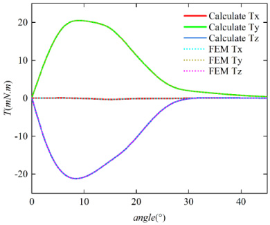
Comparison of torque conversion.
Now, the finite element method is used to calculate the torque data of the spherical motor. ANSYS software is used to draw the diagram of the reluctance spherical motor and mesh it. In ANSYS, for the three-dimensional magnetic field analysis, the solution domain surrounding the whole region is established based on the air environment (vacuum), which is similar to the balloon boundary in the two-dimensional magnetic field solution. Therefore, the magnetic field boundary conditions required by RSM automatically meet the infinite field boundary conditions without additional setting. t is only necessary to set all coils of the spherical motor as insulation boundary conditions. For the grid division setting, the maximum unit side lengths of coil, rotor and stator are set to 5 mm, 8 mm and 10 mm respectively, and the maximum number of division units is limited to no more than 2000, get the grid situation in Fig. 6.

Mesh generation.
It is unrealistic to simulate the global torque of the reluctance spherical motor. Its calculation is huge and time-consuming and it also has high requirements for computers. Therefore, the method of sampling minimum model is more reasonable.
For the local coordinate system established in the previous section, the first step is to determine the area of each stator coil. Taking the coil with zero longitude and latitude as an example, the center of the coil core is taken as the regional center point, which occupies 22.5° of east longitude and west longitude respectively, and 16.5° of north latitude and south latitude respectively. The area occupies 45° longitude and 33° latitude. Therefore, this region is regarded as the elementary model domain for torque calculation.
Through the analysis of the motor structure, it is found that the shape of the coil area on the same layer of the spherical motor is the same. Through the simulation verification, it is concluded that the torque value in its local coordinate system is the same when a single coil on the same layer is energized. Therefore, as long as the torque data in the whole region under its local coordinate system can be obtained when a single coil with the same longitude on each layer of the three-layer coil is energized, the torque data in other coil coordinate systems on the same layer can be obtained directly by “analogy”. In order to simplify the amount of simulation data, through the judgment of the motor body and the verification of simulation experiments, it is found that the area and data of the upper coil and the lower coil of the motor are symmetrical about the origin of the spherical motor. Therefore, as long as the torque data in the area under the local coordinate system when a single coil of the upper or lower layer is energized can be obtained, the data of another layer can be converted, and the torque data in other coil coordinate systems on the same layer can be obtained by “analogy”, as shown in Eq. (5). In this way, the torque value in the whole spherical motor area can be obtained quickly.
In this paper, the torque data are prestored and interpolated to calculate the torque value of the motor movement process. It is necessary to obtain a certain amount of torque data first. Through comparison, it is found that the calculation of torque data in prestored rotor coordinate system is large and time-consuming. Taking 1° as the sampling interval, the number of sampling points is 1980. The selection of torque data in prestored stator coordinate system is relatively simple, with 1485 sampling points.
In the experiment, if the current is greater than 3 A, it is easy to damage the driving circuit equipment, and the current exceeds 2 A has reached the saturation state. For the middle and upper coils, a single coil M1 and T1 are powered on, and the currents are 0.5 A, 1 A, 1.5 A, 2 A, 2.5 A and 3 A respectively. Taking 1° as the sampling density in the region, each region contains 1485 sampling points, which are simulated and calculated by ANSYS. The obtained torque data are stored in 18 tables in the upper and middle layers, and the lower torque is obtained by conversion. The final torque map can be obtained by superimposing the torque under different current conditions, as shown in Fig. 7, where lon and lat are the longitude and latitude in the stator coordinate system. Figures 7(a)–7(c) show the torque in the three coordinate axes of the middle single coil, Figs 7(d)–7(f) show the torque in the three coordinate axes of the upper single coil, and Figs 7(g)–7(i) show the torque in the three coordinate axes of the lower single coil.

Three layers of single coil torque waveform diagram.

(Continued).
According to the verification conclusion in Section 2., the local coordinate system and the global coordinate system can be converted to each other. The corresponding torque data are also obtained in the previous section. Therefore, when any coil is energized, the torque at each position in the process of rotor motion can be calculated by linear interpolation through the stored torque value, and finally the torque in the global coordinate system can be obtained by projection conversion.
For the rotor, the spherical motor center is the coordinate origin, the Z-axis direction is the output axis direction, the X-axis points to the center of rotor pole 1, and the Y -axis points to the midpoint of rotor pole 2 and 3, where O − dqp represents the rotor coordinate system as shown in Fig. 9.

Rotor marking diagram.
Firstly, the initial position information of six rotor poles shall be determined, and the longitude and latitude position information of the rotor pole shall be converted into three-degrees-of-freedom coordinates to facilitate the quaternion calculation of the rotor coordinates. For any point P (x, y, z) between the spherical surface and the spherical center L, as shown in Fig. 10, it can be transformed through the relationship between angles, and its orthogonal coordinate system and longitude and latitude conversion formulas are as shown in Eqs (6) and (7).
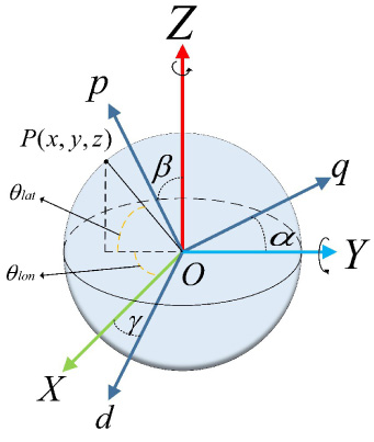
Coordinate transformation and Euler angle.
After obtaining the rotor coordinates of three-degrees-of-freedom, when the rotor rotates to a new position, the coordinates can be calculated by quaternion [19,20]; that is, the new coordinates rotated in the global coordinate system can be obtained by Eqs (8) and (9), and then converted into longitude and latitude coordinates by (6). After calculating the longitude and latitude coordinates of the rotor position during rotation, it is also necessary to judge the position.
The area of the coil and the range of motion of the rotor are different. For the middle-level coil, the longitude direction of the rotor motion area is 360°, and the dimension is 33° north and south respectively. When the upper and lower coils are powered on, the motion range is 360° longitude direction, and the dimension direction is 33° South or North relative to the center position of the upper or lower coils. The motion area is beyond the coil area. Through analysis, it is found that the torque its corresponding motion range is zero at longitude 30° and the maximum at longitude 22.5°. When the dimension direction is 16.5°, the torque is the maximum, when the dimension is 33°, the torque is the minimum, close to 0. When the dimension exceeds 33°, the torque is 0. When the rotor moves to this area, the torque data at the required position can be obtained by multiple polynomial fitting through the prestored torque data, as shown in Eq. (10).
When the rotor rotates to any position within the operation range of the spherical motor, the new longitude and latitude coordinates after the rotor rotation are obtained through the combination of multiple coordinate changes and quaternion calculation. First, it is necessary to determine whether the rotor teeth are located in the coil area by Eq. (11) below

Linear interpolation graph.
If the rotor is not in a single stator area, the polynomial fitting method described above needs to be carried out to calculate the data of 8 similar points Q11, Q12, Q13, Q14, Q21, Q22, Q23, Q24 around the rotor; Where Q11, Q12, Q13, Q14 are the values closest to the lower boundary between the actual current and the storage current, and Q14, Q21, Q22, Q23, Q24 are the values closest to the upper boundary between the actual current and the storage current. At the same time, the longitude and latitude positions of the rotor pole under the two currents are rounded up and down to obtain the position information of these eight points. If it is located in the area, the sampling data of 8 similar points around the rotor can be obtained directly from the prestored torque data, the position of each point is shown in Fig. 11. T1 can be obtained by interpolation of Q11 and Q13, T2 can be obtained by interpolation of Q12 and Q14, B1 can be obtained by interpolation of Q21 and Q23, and B2 can be obtained by interpolation of Q22 and Q24. Then P1 can be obtained by interpolation of T1 and T2, P2 can be obtained by interpolation of B1 and B2, and finally O can be obtained by interpolation of P1 and P2. P1 and P2 are the torque data under two different currents. Their calculation formula is shown in Eq. (12) to obtain the torque value under the final position and current, and the schematic diagram is shown in Fig. 11.
The interpolated torque value also needs to be projected. Each coil has its own local coordinate system, and the interpolated data are also in the local coordinate system. Therefore, it is necessary to project all the data in the local coordinate system to the global coordinate system, so the calculated torque data are the torque data in the global coordinate system. The projection formula is shown in Eq. (13) below
In order to verify the correctness of the model under the single coil, the rotor is located at the initial position with longitude and latitude of 0°. 1.2 A current is applied to M2 coil, and the rotor will pitch from −16° to 16° around Y -axis; B5 coil is energized with a current of 2.2 A, and the rotor spins from −30° to 30° around the Z-axis.
Comparison curves of the torque motion states: (a) spinning motion; (b) pitching motion.
The torque value calculated by single coil interpolation during motion and the comparison results of ANSYS simulation torque are shown in Fig. 12, respectively. The two results are highly consistent and the torque waveform is highly consistent. Because the friction of reluctance motor itself is small, the model is effective.
Obtain dynamic error coefficient
The operation of the motor requires the adjacent coils to be energized. It is found that for the 24 stator coils of the reluctance spherical motor, the nonlinear interference between indirect adjacent coils is small, and the farther the distance is, the smaller the error is. For a pair of coils with a difference of 180°, the minimal influence can be ignored and superimposed directly. The formula is shown in Eq. (14). For the reluctance spherical motor, the continuous commutation of the adjacent coils makes the motor run. Therefore, it is necessary to focus on the coupling relationship between adjacent coils and iron core saturation.
The motion of the reluctance spherical motor is a combination of spin and pitch motion in order to shorten the calculation time and reduce the amount of data storage. Through the analysis of the magnetic field and simulation data of the motor, the torque of the spin motion and pitch motion of the motor in different longitude and latitude has the same regular distribution, but there are different values. The torque of the same movement under different currents also has the same regular distribution and is only different in value. However, due to the saturation of the stator core, it is verified that the motor reaches the saturation state when the current reaches 2 A in order to shorten the torque calculation time under different currents and ensure the accuracy of calculation data. Considering the piecewise linearization of the current, 0 ∼ 2 A is a section and 2 ∼ 3 A is another section. In the corresponding areas of the two sections, the difference of dynamic error parameters is very small. Therefore, it is only necessary to consider the dynamic error parameters under each current in the two sections. It is found that under the influence of nonlinearity, the higher the coincidence degree between rotor teeth and stator, the greater the superposition error.
The rotor is located at the position with zero longitude and latitude. Through single coil interpolation is used to calculate that M1 and M2 coils and their diagonal coils are energized with 1 A current respectively. Select four latitude positions, calculate the torque in the global coordinate system during the rotor motion from −25° to 25° spin motion, and then calculate the torque under the same motion when M1 and M2 are energized with 1 A current at the same time. Single coil interpolation is also used to calculate the 1 A current of M1 and T1 coils and their diagonal coils respectively. Select five longitude positions, calculate the torque of the rotor in the global coordinate system during the pitch motion from −16° to 17°, and calculate the torque under the same motion when 1 A current is applied to M1 and T1 at the same time. Equation (15) is used to calculate the dynamic error coefficient, and the results are shown in Fig. 13. When the rotor is far away from the coil, the error coefficient is very large. When the rotor moves to the center of the coil, the value of the error coefficient is very small. The reason is that the torque value is very small at this time. The instability of finite element simulation leads to obvious torque error.

Comparison curves of the error coefficient motion states: (a) spinning motion; (b) pitching motion.

Several important positions: (a) just contact; (b) 5° position; (c) alignment.
For any group of adjacent coils and their diagonal coils, select 1 A and 3 A current respectively, and calculate the torque in three important cases of spin or pitch motion, as shown in Fig. 14. The single coil calculation torque method in the previous section is used to calculate the torque of two adjacent single coils and their diagonal coils in the global coordinate system, and the rotor is in the same position for spin or pitch motion. After the superposition of two single coil torque data and the comparison with the synthetic torque of adjacent coils at the corresponding position of the simulation, the value of dynamic error coefficient under different sectional currents is calculated, and the formula is expressed as Eq. (15).
During the operation of the rotor of the spherical motor, it is necessary to simultaneously energize the adjacent coils for commutation, so as to make the reluctance spherical motor spin or pitch. For a pair of adjacent coils, in order to obtain an accurate model and reduce the error. The dynamic error coefficients of spin and pitch motion obtained in the previous section are fitted by bivariate polynomial respectively, and the formulas are shown in Eqs (16) and (17). The error coefficient is “symmetrical” about the center line of the stator coil, and the corresponding error coefficient can be obtained according to the corresponding position by using polynomials.
According to the operation requirements of motor rotation and pitch, the torque in the global coordinate system calculated by single coil is used, and a pair of coil torque is obtained by linear superposition of diagonal coils. Then the torque is multiplied by the error coefficient corresponding to the angle and current, and finally superimposed under adjacent coils to obtain the multi coil synthetic torque. The formulas are shown in Eq. (18).
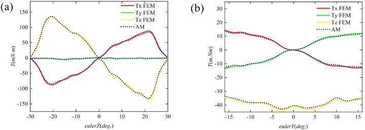
In order to verify the correctness of the model, M2 and M3 coils and their corresponding diagonal coils are energized with 1 A and 2 A currents, the longitude and latitude of the rotor is set to zero, and the rotor spins from 0° to 30° around the Z-axis. T5 and M5 coils and their corresponding diagonal coils are energized with 1 A current at the same time, and the rotor spins 180° horizontally and pitches from 0° to 30° around the Y -axis. The torque value calculated by multiple coils during movement and the comparison results of ANSYS simulation torque are shown in Fig. 15.

Three dimensional torque comparison of multicoil: (a) spinning motion; (b) pitching motion.

The experiment platform.
The calculated torque value is basically consistent with the output torque obtained by ANSYS simulation, but there is a certain error. The main reasons for the error between them are described below. Firstly, the simulation process of ANSYS software is unstable under the influence of computer, and there will be a certain fluctuation of torque. When the torque is very small, the influence of this fluctuation is more obvious. Secondly, in the process of motor torque superposition, there is a certain difference between the fitting error coefficient and the actual error coefficient, resulting in a small amount of error in the superposition.
The experimental platform of the torque model is shown in Fig. 16, including computer, DC power supply, driving circuit, motor prototype and torque detection bench. The torque detection bench is composed of two 57 stepper motors, two torque sensors, 57 motor controller, planetary reducer, rotating support and stepper motor driver. Since the motor is symmetrical about the X- and Y -axis structure, the horizontal equipment can be directly used to control the operation of the motor around the X- and Y -axis directions. The vertical direction equipment is used to control the movement of the motor around theZ-axis direction. The 24 stator coils of the motor are independently powered by 24 driving units through STM32 chip, and each current can be controlled by the computer. In order to verify the feasibility of the torque model, the experimental data are compared with the calculated values of the model. In order to reduce the measurement error and friction error of the motor in the experiment and facilitate control, the rotor offset is manually adjusted in the spin motion experiment. Two pairs of adjacent coils are selected with longitude and latitude of 0° and longitude 45° and latitude 0° and their diagonal coils are applied with 1 A and 1.5 A current respectively. The spin motion torque is measured from 0° to 20° around the Z-axis.
The comparison of the experimental results is shown in Fig. 17. Through the comparison, it is found that the torque trend obtained by the torque model and the experiment is the same, and there is a certain error in the value, of which the maximum error is 15 m⋅Nm. Through the error analysis of the data, the root mean square error is 6.33 m⋅Nm. The main causes of experimental error are as follows: 1. The torque sensor is manually installed on the rotor output shaft, which may not be firmly installed; 2. There is also a certain friction between the bench for testing torque and the spherical motor during operation; and 3. During the experiment, the initial position of the rotor is manually calibrated, so the angle will deviate during the spin movement of the rotor.

Comparison of experimental results.
The modeling of the reluctance spherical motor is still in the initial exploration stage. The difficulty of the motor modeling lies in the magnetic saturation at the stator core and stator yoke. Due to the existence of nonlinearity, the reluctance spherical motor can not be linearly superimposed with most permanent magnet spherical motors to obtain the global torque under different currents. In this paper, the reluctance spherical motor is transformed into a single coil to model the elementary torque between the corresponding rotors. By establishing the local coordinate system of the stator, the elementary torque in the model under single coil is calculated by ANSYS software, the torque value within the motion range of the whole rotor is built by polynomial fitting, and the calculated position torque is calculated by using the derived multiple linear interpolation formula, and finally projected into the global coordinate system. The dynamic error coefficients are obtained according to several important positions and fitted by bivariate polynomials. The torques of adjacent coils are corrected and superimposed based on the dynamic error parameters to obtain the multicoil synthetic torque.
This method uses the elementary model of torque to avoid the consumption of a lot of computing resources and greatly reduces the amount of computing. At the same time, the accuracy of the modeling method is also verified by simulation and experiment.
Footnotes
Acknowledgement
This work is supported in part by the Key Project of the China National Natural Science Foundation (51637001) and the Nature Science Research Project of Anhui province (1908085QE236).