
Abstract
In the service of antenna arrays, especially for the large-scale antenna arrays, the deformation of the antenna structure is inevitable due to the influence of many structural factors. Therefore, effective compensation for the electrical performance of the antenna is one of the important means to ensure its normal and stable operation. An electrical compensation method based on the genetic algorithm to change the phase of the radiating element is proposed, which also considers the quantization error of the phase shifter. Under the 0.46𝜆 deformation condition, the left side lobe level of the horizontal radiometer with the worst performance deterioration is compensated by 2.15 dB, reaching the ideal state before deformation. The objectives and constraints in the optimization model can be adjusted according to the actual work requirements. The correctness and feasibility of proposed method are verified by an antenna array with 8 × 32 radiating elements.
Introduction
Antenna arrays have been widely used in the military field, for example, ground-based radar, airborne radar, shipborne radar and so on, featuring high gain, strong reliability, strong tracking capability, and good stealth performance [1–3]. However, in the process of service, under the influence of many structural factors such as gravity, wind, solar irradiation, assembly errors, the antenna structure will inevitably deform from original state. When the deformation accumulates to a certain extent, it will affect the antenna performance, such as beam pointing deviation, sidelobe level rise, etc. Finally, the radiation characteristics deviate from the design goal [4–6].
In actual engineering, in view of the deterioration of the radiation characteristics caused by the structure deformation of an antenna array, the commonly used compensation methods can be divided into two categories: structural compensation and electrical compensation. There are two kinds of structural compensation methods: active array adjustment and self-adjustment structure using shape memory materials. Active array adjustment refers to the use of multiple actuators, hydraulic rods or other structural adjustment devices to work together to control the deformation and maintain the flatness of the antenna array. Large-scale antenna arrays can be divided into several large subarrays that can be adjusted through the movable supporting rods [7]. The self-adjustment of shape memory materials is to use the characteristics of the materials and embed them in the antenna array. When the antenna structure is deformed, the shape memory material can provide opposite deformation to compensate the antenna deformation. For instance, embedding the shape memory alloy wire in the structure can be used to compensate the deformation of the antenna structure due to high temperature [8]. The method of mechanical compensation is to apply external force to the antenna array to improve its structural deformation. Generally speaking, the overall flatness of the antenna is controlled as the compensation target, which can not achieve sufficient accuracy for the electrical performance.
Electrical compensation methods mainly include phase compensation and optimal approximate compensation. Phase compensation is to convert the position offset of each radiating element in antenna arrays into the change of its excitation phase. It is usually combined with the random phase feed method to adjust the excitation phase and improve the pointing accuracy and sidelobe level of the antenna [9]. The optimal approximation refers to the overall approximation of the distorted pattern and the desired pattern to obtain the best compensation excitation under struture deformation [10].
Structural compensation methods are often used for large arrays and have poor compensation accuracy. In electrical compensation, the phase shift limitation of phase shifter is rarely considered. The common random phase feeding method is used to calculate the probability. In the statistical sense, it can eliminate the pointing offset and suppress the parasitic sidelobe [11]. However, the effect of random phase feeding compensation is unstable. In this paper, genetic algorithm is used to optimize the compensation phase, which can effectively control the error and has high compensation certainty. Good compensation effect is achieved in the actual compensation. Firstly, the electromechanical coupling model is used to calculate the far field of the array, and the ideal compensation phase of array deformation compensation is obtained. Secondly, the ideal compensation phase is quantized according to the minimum phase shift phase of the phase shifter. Finally, the algorithm is used to optimize the quantization phase and obtain the final actual compensation phase that meets the engineering requirements.
Far field optimal compensation method
Electromechanical coupling model
Using the isolated element pattern, the radiation pattern of the array can be obtained [12,13].
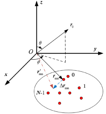
Radiation diagram of the mnth unit.

Schematic diagram of genetic algorithm execution process.
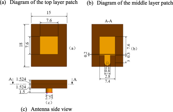
Design parameters of antenna unit.

Perspective view of antenna unit.
As shown in Fig. 1,
The model of simulation array.

Simulation analysis of 13 mm downward bending deformation.

Comparison diagram of deformation compensation for upward bending of 13 mm through simulation analysis.
After the array is deformed, The far field phase compensation formula is as follows:
Simultaneous formulas (1) and (3), we can get the exact compensation phase as
On the basis of
The optimization target is the radiation parameters of the pattern, such as side lobe level and beam direction. Genetic algorithm is adopted for algorithm optimization, which is an optimization algorithm inspired by biological natural selection, evolution and genetic mutation mechanism. It encodes the parameters that need to be optimized into the chromosome, and obtains the optimal solution of the problem by adopting certain optimization objectives and constraints through chromosome inheritance, crossover, variation and survival of the fittest [14,15]. In the genetic algorithm used, the initial population size is 10, the binary code length is 256, the set number of iterations is 300, the hybridization rate is 0.25%, and the mutation rate is 0.01%. The final iterative convergence criterion is that the main lobe and left and right side lobes of the horizontal and vertical planes meet the set error range. The specific execution and calculation process of the program is shown in Fig. 2. The final output individual is the compensation phase that meets the conditions.
In order to verify the optimization effect, simulation analysis and experimental test are carried out respectively.
Antenna and array design
In this paper, a patch antenna with a working frequency of 10 GHz and a double-layer dielectric design with a relative dielectric constant of 2.2 are used. The absolute bandwidth of the designed antenna is 9.0 GHz–10.8 GHz. The antenna unit is a double-layer structure, in which Fig. 3(a) is the schematic diagram of the upper layer patch structure, Fig. 3(b) is the schematic diagram of the middle layer and parasitic patch structure, and Fig. 3(c) is the overall side view of the antenna structure. Figure 4 shows the three-dimensional structure model of the antenna. Figure 4(a) is the Upper layer medium and patch, Fig. 4(b) is the Middle layer medium and parasitic patch, and Fig. 4(c) is the Bottom coaxial port. The antenna uses T-type microstrip line side feed [15]. The double-layer dielectric patch antenna can greatly reduce the size of the antenna while ensuring the radiation characteristics of the antenna, so as to control the size of the antenna array, or realize more array units on the array of predetermined size.
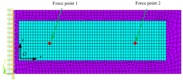
The antenna model shown in Fig. 5, and it is built through the ANSYS. There are eight rows in the vertical direction and thirty-two columns in the horizontal direction. The array elements are spaced 15 mm in the horizontal direction and 18mm in the vertical direction. The 32 units in the horizontal direction adopted Taylor excitation distribution, and the 8 units in the vertical direction adopted uniform excitation distribution. In the simulation analysis and experimental test, the left side of the array is designed to be fixed, and an external force is applied to the back of the array to guide the deformation of the array.
Bring deformed array into the Electromechanical coupling model to verify the compensation method. Two deformation compensation cases are selected, and the results of ideal, deformation and compensation are compared respectively.
Simulation analysis of 13 mm upward bending
The upward force is applied on the back of the array to make it bend upward. The displacement of the outermost array element reaches 13 mm. The deformation diagram is shown in Fig. 6, and the comparison diagram of the compensation effectis shown in Fig. 7.
Simulation analysis of 13 mm downward bending
The downward force is applied on the back of the array to make it bend downward. The displacement of the outermost array element reaches 13 mm. The deformation diagram is shown in Fig. 8, and the comparison diagram of the compensation effectis shown in Fig. 9. The data comparison is shown in Table 1.

Simulation analysis of 13 mm downward bending deformation.
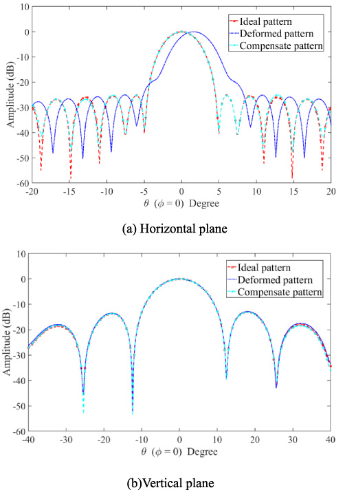
Comparison diagram of deformation compensation for downward bending of 13 mm through simulation analysis.
Front of the antenna array.
Side of the antenna array.
Test status of antenna array.
Comparison of deformation compensation data
It can be seen through the comparison Fig. 7, Fig. 9 and simulation data Table 1 above that when the deformation of array is symmetrical, the deformation of the pattern on the horizontal plane is opposite, while the deformation of the pattern on the vertical plane is the same, both of which can achieve favorable compensation effect.
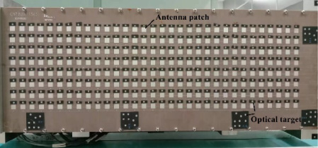
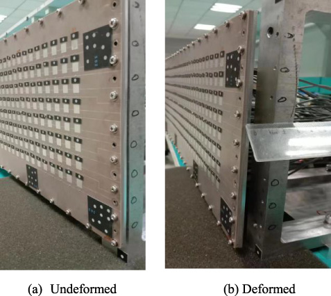
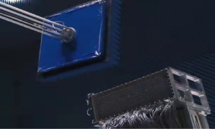
On the basis of completing the simulation analysis, the preliminary experimental verification is conducted for the antenna array. Due to the advantages of industrial photogrammetry, such as non-contact, high measurement accuracy [16–18], and fast measurement speed, the structural deformation measurement of the phased array antenna adopts it to measure the deformation of the antenna array. As shown in Fig. 10, an optical target is connected to the upper side of each unit, and its coordinates are used as the position coordinates of the antenna. Figure 11(a) and (b) show the undeformed and deformed sides of the array respectively. The antenna under test is shown in Fig. 12.
The experimental measurement process is as follows. Firstly, the position coordinates of the array elements are measured without deformation. Secondly, deform the array and measure the coordinates again. Finally, the deformation of the array and the displacement of each element are obtained.
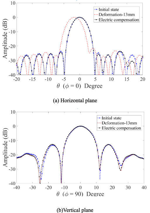
The following is the deformation and compensation test results of antenna structure. In the test, the left end of the array is fixed and the right end is tilted forward. The maximum deformation is about 13 mm. Figure 13 is compensation comparison diagrams. In the figure, the initial state refers to the ideal state under experimental conditions, and electrical compensation is the compensation mode.
From the comparison of Fig. 13 and Table 2, it can be seen that the array deformation has a greater impact on the horizontal plane. In addition, the pointing of the pattern on the horizontal plane and the change of sidelobes is obvious. The experiment shows that the overall effect of compensating sidelobes and beam pointing is satisfactory. It can be seen through the simulation and experiment that when the array is deformed upward, the pattern pointing on the horizontal plane deviates to the left.
Comparison of experimental compensation data for upward bending deformation of 13 mm
Comparison of experimental compensation data for upward bending deformation of 13 mm
Note: LSLL is Left sidelobe level, RSLL is Right sidelobe level, BD is Beam direction, HPBW is Half-power beam width.
The electromechanical coupling model can be established for an antenna array to effectively calculate the deformation mode and compensation phase. The compensation scheme can obtain the best compensation phase of an antenna array under structure deformation. At the same time, the optimization objectives and constraints can be adjusted according to the actual work needs to improve the calculation efficiency. The effectiveness of the proposed method has been experimentally verified.
Footnotes
Acknowledgements
This work was supported by the National Key R&D Plan “Gravitational Wave Detection” Key Special Project [Grant No. 2021YFC2203501]. The authors would like to thank Prof. Bao Hong for his helpful insights.