
Abstract
Increasing the switching frequency of direct current–direct current converters is effective in reducing the size of magnetic components used in converters. However, as the switching frequency increases, the loss and heat generated by the magnetic components increase. Therefore, in this study, a magnetic tape that bypasses the magnetic flux in the windings of magnetic components is proposed to reduce the loss and heat generation of these components. The effect of suppressing the temperature rise of magnetic components with a magnetic tape during the converter drive was investigated. The temperature rise of a 1-MHz 100-V/200-V 800-W boost inductor was reduced by 16.8 K by applying the magnetic tape. Additionally, applying the magnetic tape to the inductor reduced the heat generation.
Introduction
Increasing the drive frequency is effective for downsizing magnetic components used in direct current–direct current (DC–DC) converters [1,2]. The excellent low ON-resistance and fast switching characteristics of gallium nitride and silicon carbide power devices can significantly increase the switching frequency of DC–DC converters compared with silicon power devices [3,4]. However, as the switching frequency increases, the loss and heat generated by the magnetic components increase. Losses generated by magnetic components can be broadly categorized into two: iron losses in the core and copper losses in the windings. Iron losses in cores have been reduced with the advent of high saturation magnetic flux density and low iron loss materials, such as pressed magnetic cores, which are formed by mixing magnetic powder and binder and applying pressure, and magnetic composite materials to which no pressure is applied [5–7]. Among the copper losses in windings, eddy current losses are problematic at high frequencies. As magnetic flux penetrates a wire that makes up windings, eddy current loss occurs inside the wire. Thus, eddy current loss can be reduced by loading a magnetic material around a copper wire to bypass the magnetic flux that penetrates the wire [8,9]. In a previous study [9], we proposed magnetic tape loading a magnetic layer around a copper wire to control the layer thickness. However, the effects of the magnetic tape fabrication method and the ratio of magnetic powder and binder used in magnetic tapes on the magnetic properties were not reported. Moreover, the effect of suppressing the temperature rise of the magnetic components of the magnetic tape during converter drive remains unexplored. Therefore, in this study, we report the magnetic tape fabrication method, the component materials of these tapes, and the temperature rise characteristics of an inductor using tapes operated by a 1-MHz 100-V/200-V 800-W boost converter.
Magnetic tape fabrication method and magnetic properties
Advantages of applying magnetic tape
Figure 1 shows the advantages of applying magnetic tape. Figure 1(a) shows a principle of eddy current losses suppression. Eddy current losses inside the copper wire is caused by eddy currents flowing inside the copper wire in the direction to counteract the magnetic flux generated by the core gap and nearby the copper wire as it penetrates the copper wire. Therefore, by winding magnetic tape, which has higher magnetic permeability and resistivity than the copper wire, around a copper wire’s outer circumferenceeddy current losses can be suppressed by inducing the magnetic flux that penetrates the copper wire into the magnetic tape. Figure 1(b) shows the principle of increase in inductance. Wrapping magnetic tape around a copper wire’s circumference creates a magnetic circuit with a very short magnetic path length around the copper wire, thereby increasing inductance.
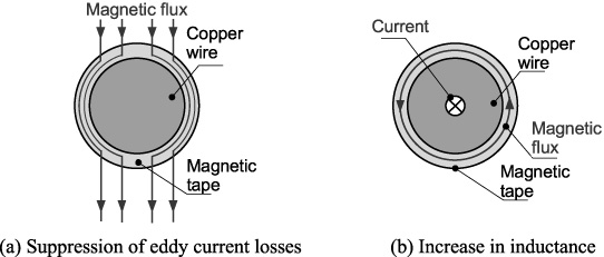
Advantages of applying magnetic tape.

Boost chopper circuit.
Figure 2 shows the equivalent circuit diagram and inductor current waveform of a boost chopper circuit. When switch SW1 is turned on, the input voltage V in is applied to the inductor L and magnetic energy is stored in the inductor. Next, when switch SW1 is turned off and switch SW2 is turned on simultaneously, the back electromotive force of the inductor is applied to the output in addition to the input voltage. Thus, by alternately turning SW1 and SW2 on and off, respectively, the inductor is charged and discharged to boost the voltage. Additionally, a current i L flows through the inductor in which a triangular ripple current Δi L is superimposed on the input DC I in .
The following is the equation for the ripple current Δi
L
of the inductor:
From Eq. ((1)), the ripple current Δi L is inversely proportional to the inductance L. Therefore, by applying magnetic tape to the inductor and increasing the inductance, the ripple current Δi L and loss can be reduced. The reduction of ripple current due to the increase in inductance occurs not only for boost chopper converters but also for buck chopper converters.
Recipe for slurry
Recipe for slurry
Surface photos and the complex relative permeability of magnetic tapes
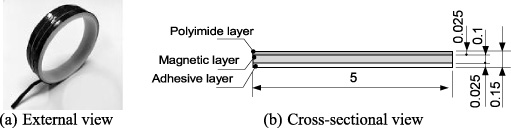
Structure of the magnetic tape (unit: mm).
Figure 3 shows the magnetic tape structure. Particularly, Fig. 3(a) and (b) shows the external and cross-sectional views, respectively. The magnetic tape comprises a 0.025-mm-thick polyimide layer, a 0.1-mm-thick magnetic layer, and a 0.015-mm-thick adhesive layer. A slurry mixed with iron-based amorphous sphere powder (average diameter D50 = 3 μm), silicone resin with volatile organic solvent, silane coupling agent, lubricant (isopropyl alcohol), and defoamer was applied to the polyimide base material using a bar coater to form the magnetic layer. The adhesive layer was formed by applying a mixture of two silicone adhesives with a squeegee. The mechanical property required for magnetic tape is adhesive strength that sticks to the winding and does not peel off. The adhesive force required to keep the magnetic tape from peeling off from the winding depends on the shape and curvature of the winding. However, the adhesive strength of magnetic tape can be adjusted by changing the ratio of the two types of silicone adhesives used in the adhesive layer or the type of silicone used. Therefore, magnetic tape can be applied to various types of windings by adjusting the adhesive strength according to the winding structure. Magnetic powder, silicone resin, silane coupling agent, and antifoaming agent used in the magnetic layer, polyimide used in the polyimide layer, and silicone used in the adhesive layer each have a heat resistance of 200 °C or higher, making magnetic tape very heat stable. Therefore, magnetic tapes have little degradation of mechanical properties due to heat. In addition, since the magnetic powder is sealed with a silicone binder, no oxidation or other chemical changes will occur. Therefore, the magnetic properties of magnetic tape do not change over time.
Table 1 shows a recipe for the slurry. Five slurries with different volume filling ratios of magnetic powder after drying and volatilization were produced. Silicone resin served as a binder for the magnetic powder, and by changing the silicon resin’s quantity, volume filling ratio of magnetic powder was altered. A silane coupling agent was added to increase adhesion between the silicone resin and magnetic powder. The lubricant was added to reduce the slurry viscosity and facilitate smooth application with a bar coater. The amount of lubricant was standardized to that used for the slurry with the highest viscosity (volume filling ratio of the magnetic powder of 80 vol%). A small amount of defoamer was added to prevent the foaming of the slurry.
The surface photos and complex relative permeability of the magnetic tape are illustrated in Table 2. The complex relative permeability was measured using an impedance analyzer (Agilent Technologies, Inc., 4294A). Its real part is the value at 1 MHz, the drive frequency of the converter. Magnetic tape, made by mixing magnetic powder and silicon resin, has a very low iron loss, and the contact resistance of the impedance analyzer fixture is not negligible at low frequencies. Therefore, the imaginary part of the complex relative permeability, which indicates the loss of magnetic tape, shows the value at the drive frequency of 10 MHz, where the effect of contact resistance is small [10,11]. The real part of the complex relative permeability increases with an increase in the volume filling factor of the magnetic powder. However, for magnetic tapes with a volume filling rate of 70 or 80 vol%, magnetic powder agglomeration and magnetic layer dropout were observed due to very low silicone resin content. The imaginary part first increased with the volume filling ratio, reached a peak at 60 vol%, and then decreased. The 70- and 80-vol% volume fill rates were due to the smaller amount of silicone resin added, resulting in a smaller increase in retention force because the tensile stress caused by the curing and shrinkage of the silicone resin had a smaller effect on the magnetic powder.
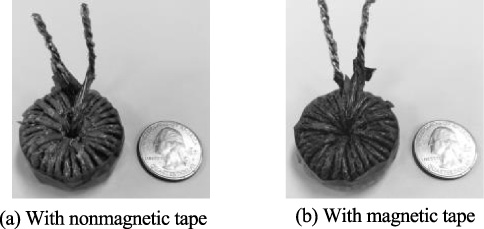
Appearance of inductors.
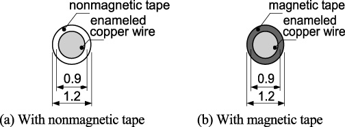
Cross-sectional view of wires (unit: mm).
Impedance characteristics of inductors.
Figure 4 shows the appearance of inductors. The inductors are toroidal inductors comprising wires (Fig. 2) wound on a toroidal core (a 30-mm outer diameter, 15-mm inner diameter, and 10-mm height) with nine and four parallel turns. The core is a pressed magnetic powder core fabricated from a mixture of iron-based amorphous sphere powder (average diameters: 3 and 10 μm) and epoxy resin in a weight ratio of 25:75:1. The core was hardened by applying a pressure of 1079 MPa during heating. The inductors were designed to enable the operation of a 1-MHz 100-V/200-V boost converter with a ripple current Δi L of approximately 14 A at an output power P o = 800 W. Considering the miniaturization of an inductor and the fact that the converter operates in current continuous mode at full load (P o = 800 W), Δi L was set to 14 A. Figure 5 depicts a cross-sectional view of the wire used in the inductors. Figure 5(a) and (b) shows an enameled copper wire (diameter: 0.9 mm) with nonmagnetic tape (thickness: 0.15 mm) and with magnetic tape (thickness: 0.15 mm), respectively. Magnetic tape suppresses eddy current losses by inducing magnetic fluxes that penetrate copper wires. Therefore, the higher the real part of the complex relative permeability of the magnetic tape, the more effective it is in suppressing eddy current losses. Therefore, among the magnetic tapes shown in Table 2, the magnetic tape with a 60-vol% volume filling ratio of magnetic powder, having the highest real part of complex relative permeability without structural defects, such as magnetic powder agglomeration and magnetic layer dropout, is used. To keep the same distance between the windings and inductor structure, a nonmagnetic tape of the same thickness as the magnetic tape is wound.
A 1-MHz 100-V/200-V 800-W boost converter.
Inductor current waveforms (P o = 800 W).
Thermal image of inductors (P o = 800 W, t = 45 min).
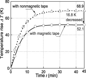
Temperature rise characteristics (P o = 800 W).
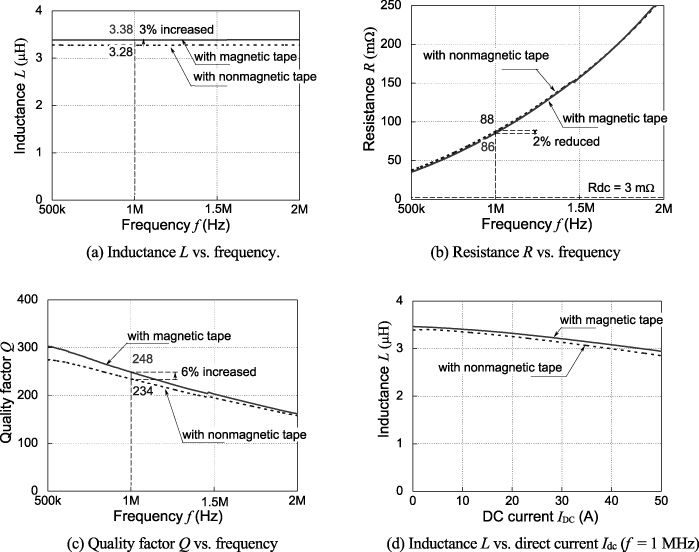
Figure 6 shows the impedance characteristics of the inductors. An impedance analyzer (KEYSIGHT Technologies, E4990A) was used for the measurement of Fig. 6(a)–(c), and an LCR meter (KEYSIGHT Technologies, E4980A) was used for the measurement of Fig. 6(d). Figure 6(a) plots inductance L against frequency. L at 1 MHz of the inductor with nonmagnetic tape and magnetic tape were 3.28 and 3.38 μH, respectively. By applying magnetic tape, L increased by 3% that of with nonmagnetic tape. Magnetic tape was wound around the copper wire’s circumference to form a magnetic circuit with a very short magnetic path length, thereby increasing the inductance. Figure 6(b) plots resistance R against frequency. DC resistance R DC was 3 mΩ for both inductors with nonmagnetic tape and magnetic tape. R at 1 MHz of the inductor with nonmagnetic tape and magnetic tape were 88 and 86 mΩ, respectively. By applying magnetic tape, R reduced by 2% that with nonmagnetic tape. The resistance caused by eddy current loss was reduced by applying magnetic tape. However, owing to the low relative permeability of the magnetic tape, the magnetic flux causing eddy current loss could not be sufficiently induced and a large resistance reduction effect could not be obtained. To solve this problem, it is necessary to change the magnetic powder material used for the magnetic tape or use a mixture of magnetic powders of different particle sizes to increase the specific permeability of the magnetic tape. Figure 6(c) plots the quality factor Q against frequency. Q at 1 MHz of the inductor with nonmagnetic tape and magnetic tape were 234 and 248, respectively. When the magnetic tape was applied, Q was higher (by 6%) than that with nonmagnetic tape because the magnetic tape reduced the resistance caused by eddy current loss and increased the inductance. Figure 6(d) shows DC superimposed inductance characteristics. The decrease in inductance with increasing DC superimposed current for both inductors with nonmagnetic tape and magnetic tape is small, and magnetic saturation does not occur. The inductance of the inductor with magnetic tape is greater than that of the inductor with nonmagnetic tape in the entire measurement range, confirming that magnetic tape does not cause magnetic saturation within this measurement range.
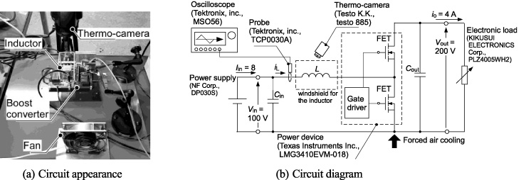
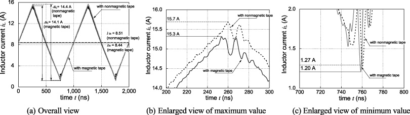
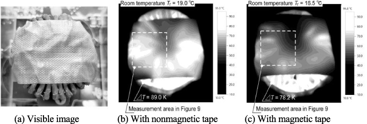
Figure 7(a) and (b) shows the circuit appearance and circuit diagram of a 1-MHz 100-V/200-V 800-W boost converter, respectively. To prevent the inductors from being affected by the wind that cools the circuit board, a windshield was installed around the inductors, and the temperature rise characteristics of the inductors during the converter drive were evaluated with a thermo-camera (Testo K. K., testo 885). The inductor currents i L were also measured using an oscilloscope (Tektronix, inc., MSO56) and current probe (Tektronix, inc., TCP0030A). Figure 8 shows the inductor current waveforms. The ripple currents Δi L of the inductors with nonmagnetic tape and those with magnetic tape were 14.4 and 14.1 A, respectively. The application of magnetic tape increased the inductance and suppressed the ripple current Δi L . Figure 9 shows a thermal image of inductors (output power P o = 800 W, time t = 45 min). The temperature rise reduction effect of applying magnetic tape to the inductor can be confirmed from the thermal image. To accurately compare the temperature rise characteristics of the inductors with nonmagnetic tape and those with magnetic tape, the maximum temperature rise value of the measurement area in Fig. 9, whose reflectance was matched by applying emission tape, was measured is plotted against time in Fig. 10. The saturation temperature rise ΔT of the inductors with nonmagnetic and magnetic tape were 68.9 and 52.1, respectively. The application of magnetic tape to the inductor reduced eddy current losses and ripple current Δi L and suppressed the temperature rise of the inductor during converter drive.
Conclusions
In this study, we propose magnetic tape as a method for reducing heat generation in magnetic components and clarify the effect of the mixing ratio of magnetic powder and silicone resin on the magnetic properties of magnetic tape by fabricating magnetic tape. The real part of the complex specific permeability increased from 3.2 to 5.7 with an increase in the volume filling ratio of the magnetic powder in the magnetic tape from 40 to 80 vol%. Magnetic powder agglomeration and magnetic layer dropout occurrences in magnetic tapes as the volume filling ratio of the magnetic powder increases were also confirmed by fabricating magnetic tapes. Additionally, we fabricated inductors using the fabricated magnetic tape and evaluated their impedance characteristics. The application of magnetic tape to the inductor improved its quality factor Q by 6%. The fabricated inductors were mounted on a 1-MHz 100-V/200-V 800-W boost converter, and the temperature rise characteristics of the inductors were evaluated. By applying magnetic tape, the saturation temperature rise value of the inductor ΔT reduced by 16.8 K. Using magnetic tape, the Q and ΔT of the inductor increased by 6% and decreased by 16.8 K, respectively. These results prove that magnetic tapes manufactured using the proposed magnetic tape fabrication method can reduce heat generation in boost inductors applied to DC–DC converters. The magnetic tape bypasses the magnetic flux through winding, suppresses eddy currents, and forms a closed magnetic path around the copper wire to increase inductance. Therefore, magnetic tape can suppress heat generation not only in the inductors applied to the converter under the present driving conditions but also in various magnetic components.
Footnotes
Acknowledgements
This study was supported by the MEXT-Program for Creation of Innovative Core Technology for Power Electronics (Grant Number JPJ009777).