
Abstract
This study explores the applicability of microwave nondestructive testing to detect a metal pipe’s inner crack. Three-dimensional finite element simulations were conducted to study the inspectability of cracks using microwaves in different modes and the dependency of the reflection characteristics of microwaves on crack size. The simulation results showed that microwaves in the TM01 and TE01 modes can detect circumferential and axial cracks, respectively. The positive relationship between crack size and intensity corresponding to the reflected microwaves was obtained in simulations and then verified by experiments. In both simulations and experiments, the axial crack length showed a small influence on the results, especially for shallow crack detection. In the experiments, circumferential and axial cracks with a width of 0.3 mm were detected using microwaves. The experimental results revealed that signal amplitudes decreased when a slit penetrated a pipe wall, probably due to a microwave leakage.
Introduction
Piping systems, which are widely used in various power plants, inevitably suffer degradation for long-term operations [1]. Consequently, periodic nondestructive testing (NDT) is indispensable for maintenance. Eddy current and ultrasonic testing approaches have been widely used in pipe inspections owing to their high sensitivity. However, these methods require the movement of a probe to scan the whole pipe [2,3], which makes it time-consuming to inspect a long pipe.
To address this problem, microwave NDT using a fixed probe was proposed and proved effective for pipe inspection [4–6]. Its basic principle is that the metal pipe works as a circular waveguide while microwaves propagate inside it. Microwaves are reflected at defects due to impedance mismatching. Unlike ultrasonic guided waves [7], this technique is insensitive to defects and medium outside the pipe, as most microwave energy is confined within the pipe [8]. Earlier studies have demonstrated that this method is effective in detecting not only large defects such as wall thinning [5] but also small defects such as cracking [9–11]. Optimization of the probe structure [12] and signal processing method [13,14] were also investigated to improve the performance of microwave NDT. However, earlier studies [9–11] simulated cracking using a slit that penetrated the pipe wall with a large width (approximately 1 mm). As real cracks to be detected usually do not penetrate pipe walls, evaluating their penetration effects on microwave NDT signals is necessary. The effect of crack width also requires exploration to verify the detection ability of microwave NDT to detect narrow cracks.
Therefore, this study aims to comprehensively evaluate the feasibility of microwave NDT to detect circumferential and axial cracks with different size parameters. The sensitivity of microwaves in TM01 and TE01 modes to crack orientation was studied by numerical simulations. Based on the obtained results, microwaves in the TM01 and TE01 modes were adopted to detect circumferential and axial cracks, respectively. The effect of each size parameter (i.e., depth, width, circumferential angle for circumferential crack, and axial length for axial crack) on the corresponding microwaves’ reflection was investigated by simulations and verified by experiments. The feasibility of microwaves to detect narrow circumferential and axial cracks with a width of 0.3 mm was proved in experiments. In addition, the influence of pipe wall penetration was studied in experiments using covered/uncovered penetrating slits and nonpenetrating cracks.
Materials and methods
Numerical simulation
Three-dimensional finite element simulations were performed in the frequency domain using COMSOL Multiphysics v5.2a with its RF module (Fig. 1). The governing equation is a wave equation for the electric field in the frequency domain, as follows:
In this study, we set μ
r
= 1, ϵ
r
= 1, and σ = 0 for air inside the pipe. The inner surface of the pipe was modeled as the perfect electric conductor with a boundary condition of
The energy ratio of the microwaves reflected from the circumferential and axial cracks was calculated to indicate the reflection intensity in simulations as follows:
Size parameters of cracks in simulations
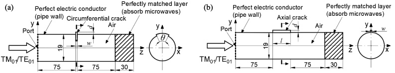
Simulation configuration: (a) circumferential crack and (b) axial crack (Unit: mm, not to scale).
Circumferential cracks and axial cracks were detected using TM01 and TE01 mode microwaves, respectively, according to the simulation results, which will be illustrated in Section 3.
Detection of circumferential cracks using the TM01 mode
Figure 2 illustrates the experiments conducted to verify the effect of the circumferential crack size on the reflection characteristics of the TM01 mode microwaves and to investigate the influence of wall penetration on the obtained results. Microwaves in TEM mode at a frequency range of 12–22 GHz with 6401 evenly spaced points were emitted from a vector network analyzer (E8363B; Agilent Technologies, Santa Clara, CA, United States) and converted to the TM01 mode through a plate-type TEM–TM01 mode converter [12]. The generated TM01 mode microwaves propagated inside a 5.5 m long, brass pipe with a wall thickness of 3 mm. This pipe consisted of a single 1 m long pipe and three 1.5 m long pipes connected through the flange connection. The reflection signals were measured as the scattering parameter using a vector network analyzer through the TEM–TM01 mode converter. A short pipe joint (wall thickness = 3 mm, length = 50 mm) with a circumferential slit was inserted into the main pipe using flange connections to emulate a circumferential crack at a location of 2.5 m (around the middle of the main pipe). An aluminum foil was used to cover the penetrating slit to emulate a nonpenetrating crack with a depth of 3 mm. Note that the nonpenetrating cracks with depths of 1 mm and 2 mm were not covered with the aluminum foil, as no opening exists on the outer surface. The maximum skin depth of the investigated microwaves into the aluminum was 0.77 μm, whereas the thickness of the used foil was 11 μm, which ensured that few microwaves could penetrate the foil. A thin brass plate with a circumferential crack structure was also used to emulate a nonpenetrating crack and was compared with the aluminum-foil-covered penetrating slit. The measured reflection signals were averaged for 30 measurements to decrease background noise.

Experimental setup for detecting the circumferential crack using TM01 mode microwaves: (a) main system; (b) short pipe joint; and (c) thin plate joint.
To detect the axial crack, a four-way power divider (D-640-4; ET Industries, Morris County, New Jersey, United States) split the TEM mode microwaves four ways, and a TEM–TE01 mode converter developed in Refs. [10,11] converted the split TEM mode microwaves into TE01 mode microwaves propagating inside the pipe (Fig. 3). In addition, a 6 m long pipe was added at the left part of the experimental setup since the TE01 mode microwaves generated by that side-incident TEM–TE01 mode converter would propagate toward two directions. Note that the length of the left pipe and that of the right are different to ensure the reflection caused by the flange connection at 3.0 m (left pipe) is not superimposed on that caused by the crack at 2.5 m (right pipe). The sweeping frequency ranged from 20 to 25 GHz with 3201 evenly spaced points. In addition to joints with a wall thickness of 3 mm, two joints with a wall thickness of 5 mm were also used to directly machine the nonpenetrating cracks with a depth of 3 mm on the inner surfaces of joints. The average of 30 measurements was also obtained, as in the experiments for the circumferential crack.
The signal processing method developed in our previous studies [13] and [14] was adopted to obtain the explicit reflection signals of cracks. The corresponding reflection amplitude was used to indicate the reflection intensity in the experiments (Fig. 4).

Experimental setup for detecting the axial crack using TE01 mode microwaves: (a) main system; (b) four-way power divider and TEM–TE01 mode converter; and (c) axial crack joint.

Processed TM01 mode microwave signals reflected from a penetrating slit (w = 0.3 mm, θ = 180°, d = 3 mm).
Table 2 lists the energy ratio of the microwaves reflected from the circumferential and axial cracks with the largest size in the simulations. The results demonstrated that microwaves in the TM01 and TE01 modes were sensitive to circumferential and axial cracks, respectively, because these microwaves induce currents on the inner surface flowing mainly in the axial and circumferential directions, respectively. Therefore, selecting a suitable microwave mode to detect the corresponding type of crack is crucial. Consequently, microwaves in TM01 and TE01 mode were adopted to detect the circumferential and the axial cracks, respectively, in the experiments.
Energy ratio of reflected microwaves using different modes and crack types
Energy ratio of reflected microwaves using different modes and crack types
Figure 5 shows the dependency of the reflection intensity of TM01 mode microwaves on circumferential crack sizes. It should be noted that it is difficult to compare reflection amplitudes because the simulations were performed in the frequency domain and evaluating reflection amplitudes by simulations requires massive frequencies. Thus, the figure presents the energy ratio obtained by the simulations as it directly affects the reflection amplitude. A positive relationship between the reflection intensity and the size parameters of the circumferential cracks was obtained in the simulations (Fig. 5(a)). The simulation results also implied that the contributions of width w, depth d, and circumferential angle θ to the reflection signals were almost at the same scale.

Influence of circumferential crack size on the reflection intensity of TM01 mode microwaves: (a) simulations; (b) experiments using different widths (θ = 180°, d = 3 mm); and (c) experiments using different depths and circumferential angles (w = 1 mm).
The positive linear relationship between the reflection amplitude and the width w of the detected circumferential crack was confirmed in the experiments (Fig. 5(b)). Although the smallest circumferential crack width in the experiments was 0.3 mm, a circumferential crack with a width of 0.1 mm could be detected through linear regression. The reflected signal from an uncovered penetrating slit was more than four times smaller than that from a covered slit with the same width. This implies that the penetration of a pipe wall causes a drop in measured signals in the microwave NDT and might mislead the operator during testing. The weakened reflection signals can be explained by the leakage of microwaves from the penetrating slit. This differs from conventional NDT methods [2,15,16] whose signals increased when detecting a through-wall crack. The above results suggest the importance of detecting a circumferential crack in the early stages when using microwave NDT. An increase in signal amplitude with either the depth d or the circumferential angle θ of the circumferential crack was also observed in the experiments (Fig. 5(c)). The results shown in Figs. 5(b) and (c) demonstrate that all the size parameters w, d, and θ of the circumferential crack have a comparable influence on the measured TM01 mode microwaves, which agrees with the simulation results. The reflection amplitude obtained using the plate joint (d = 2 mm, θ = 180°) was smaller than that obtained using a short pipe joint with a directly machined nonpenetrating crack (d = 2 mm, θ = 155°). This might be caused by the leakage of microwaves from the gap between the thin plate and the pipe. The results from a nonpenetrating circumferential crack emulated by the thin plate were comparable with those obtained by covering the penetrating slit with an aluminum foil, indicating the feasibility of using the covered penetrating slit to emulate a nonpenetrating crack in the analysis.
An increase in reflection signal intensity with w and d was also observed in the simulations (Fig. 6(a)) when detecting the axial crack through the TE01 mode microwaves. However, the effect of axial length l on reflection was much smaller than the effects of w and d. A negative effect of l was even observed at d = 1 mm.
An increase in signal amplitude with the width of the axial crack emulated by the covered penetrating slit was also observed using TE01 mode microwaves in the experiments (Fig. 6(b)). Covered penetrating slits with small widths (<1 mm) were detected, but these slits were undetectable after removing the foil. While the uncovered axial penetrating slit with width of 1 mm was detected, the measured signal amplitude decreased more than eight times after removing the foil. The results in Fig. 6(c) suggest that the larger the depth or length of the axial crack, the larger the signal amplitude, which agrees with the simulation results. Compared with the depth, the axial length slightly influences the signal amplitude, especially when the depth is small (1 mm). The results in Fig. 6 show that more attention should be paid to narrow and shallow axial cracks when using microwave NDT. Although the axial crack at d = 1 mm and l = 10 mm caused a larger reflection intensity than that at d = 1 mm and l = 30 mm in the simulations, the experimental results confirmed that a larger signal amplitude was obtained under the latter condition. The difference between the results from the nonpenetrating crack and the covered penetrating slit at d = 3 mm and l = 30 mm might be caused by the material property difference between brass and aluminum. The leakage from the gap between the aluminum foil and the pipe wall is also expected to weaken reflection. The decrease in reflection when the axial length of the uncovered penetrating slit was changed from 10 mm to 30 mm can be explained by more energy loss from the longer penetrating slit.

Influence of axial crack size on the reflection intensity of TE01 mode microwaves: (a) simulations; (b) experiments using different widths (l = 30 mm, d = 3 mm); and (c) experiments using different depths and axial lengths (w = 1 mm).
This study investigated the applicability of microwaves to detect both circumferential and axial cracks in simulations and experiments. The simulation results showed that microwaves in the TM01 and TE01 modes were sensitive to circumferential and axial cracks, respectively. A positive relationship between the reflected TM01 mode microwaves and each size parameter of the circumferential crack (i.e., width, depth, and circumferential angle) was obtained in both the simulations and experiments. However, the length of the axial crack slightly affected the reflected TE01 mode microwaves, especially for a small depth of 1 mm. Circumferential and axial cracks with a small width of 0.3 mm were detectable using microwaves. In addition, the amplitude drop in signals was observed when detecting the uncovered penetrating slit in the experiments. This indicates that signals due to a crack that penetrates a pipe wall are much smaller than those due to a crack that does not penetrate a pipe wall, unlike other NDTs. Thus, it is necessary to detect nonpenetrating cracks in the early stages when using microwave technology.
Footnotes
Acknowledgements
This work was supported by JST SPRING, grant number JPMJSP2114.
Conflict of interest
The authors declare that they have no known competing financial interests or personal relationships that could have appeared to influence the work reported in this paper.