
Abstract
This paper presents a non-contact three-point bending device based on magnetic levitation technology, in which a specimen can be bent while being levitated. As the levitated object needs to withstand an increasing bending load in levitated state, this requires the control system to have a strong robustness. Therefore, a centralized sliding mode controller (CSMC) was proposed for the levitation. Furthermore, based on CSMC, an adaptive centralized sliding mode controller with the bending load as scheduling variable (ACSMC), which is the novelty of this paper, were proposed to deal with the disturbance caused by the bending load. Simulation results demonstrated that ACSMC has good robustness to three typical bending loads, i.e., ramp load, sine load, step load. Finally, experiments were conducted and experiment results demonstrated that ACSMC allows the device to withstand ramp bending load, sine bending load and step bending load up to 50 N.
Keywords
Introduction
Magnetic levitation (Maglev) technology avoids mechanical contact and therefore does not require lubricating oil. As a result, it is advantageous in terms of maintenance. For this reason, maglev technology has been applied in various fields, such as magnetic bearings [1], maglev trains [2], and bearingless motors [3]. Paper [4] proposed a novel application of magnetic force to a non-contact tension testing device. In the device, since a tension force is applied to a specimen in a non-contact way, it is possible to allow testing in liquid environment. However, the non-contact mechanism only exists at one end of the specimen, therefore it is difficult to perform a testing in a closed environment such as vacuum, special gas. As a solution, paper [5] proposed a completely non-contact tension testing device using maglev technology. As a result, only the specimen and fixtures required for levitation need to be placed in a special environment such as vacuum, corrosive liquid, corrosive gas, etc., and the space for holding the special environment is reduced, so the tension testing becomes easier. In addition, not only tension testing device but also other types of testing devices, such as three-point bending testing device [6,7], torsion testing device, fatigue testing device, can be developed using maglev technology. Therefore, in this paper, a magnetic levitation three-point bending device (MLTBD) was presented.
The most difficult problem in developing maglev three-point bending testing device is to maintain levitation while the levitation object is under a wide range of bending load. Generally, the bending load can be treated as a disturbance force, and then it can be compensated by the integrator of a PID controller. However, traditional PID controller is designed based on a fixed working point of the current of electromagnet, as the bending load increases, to compensate the bending load, the current will increase, and the working point will inevitably change, making the initial PD gain not fit the new working point. In other words, traditional PID controller cannot cope well with the nonlinearity inherent in maglev system. Sliding mode controller (SMC) has strong robustness due to its insensitivity to system uncertainties and external disturbances. Therefore, it has aroused extensive attention in the field of maglev. Lan Yipeng et al. [8] proposed a sliding mode control method with a fuzzy switching gain adjustment to resist external disturbance for a maglev feed platform, the controller was proved to improve the dynamic performance of the system. Sun Yougang et al. [9] added a radial basis function neural network estimator to a sliding mode controller for a maglev railway system, and the experiment results showed the controller has strong robustness with reference to uncertainties and disturbances. Zhang Chunliang et al. [10] designed a variable universe fuzzy sliding mode controller for a maglev ball system, the controller effectively improved the accuracy of the control system and weaken chattering. But most existing maglev sliding mode controllers are decentralized controller, i.e., individual controller for single-DoF levitation. Paper [11] argued that decentralized controller tends not to be as good as centralized controller in dealing with multi-DoF maglev system due to the coupling between the multiple degrees of freedom. As MLTBD is a 2-DoF maglev system. In this paper, a centralized sliding mode controller (CSMC) was proposed to better deal with the coupling between the two degrees of freedom. However, since the bending load is a fairly large range of force, pure sliding mode controller is still not sufficient to cope with it. Therefore, based on CSMC, an adaptive centralized sliding mode controller with the bending load as scheduling variable (ACSMC), which is the novelty of this paper, were further proposed to deal with the disturbance caused by the bending load.
Structure and principle of MLTBD
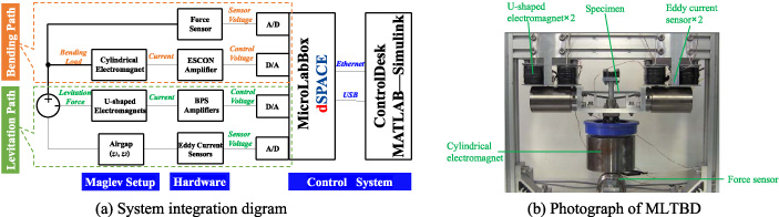
As shown in Fig. 1(a), the prototype mainly consists of two U-shaped electromagnets, two eddy current sensors, a levitated object, a cylindrical electromagnet, and a force sensor. The two U-shaped electromagnets are used to produce levitation force for the levitated object, while the two eddy current sensors are used to detect the position of the two iron cylinders. The cylindrical electromagnet is used to produce a non-contact bending load to bent the specimen in the levitated object, while the force sensor is used to measure the bending load in real time.
The principle is, as shown in Fig. 1(b), firstly, the two U-shaped electromagnets and the two eddy current sensors work synergistically to maintain the levitation. The levitation forces will keep the levitated object in a fixed vertical position. As shown in Fig. 1(c), after the levitation is stable, the cylindrical electromagnet will be energized to produce a non-contact bending load to the iron disk, so that the punch will be pulled down to bend the specimen.
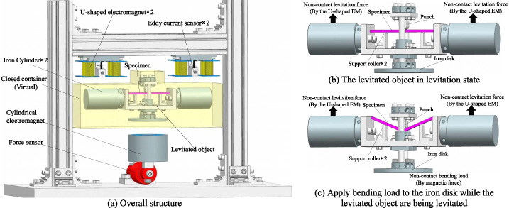
Illustration of MLTBD.
Plant model
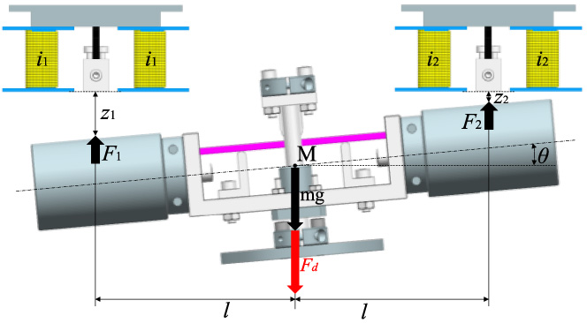
Illustration of the plant model.
First of all, a levitation plant model, which is cited from paper [5], was built. As illustrated in Fig. 2, i1 and i2 are the currents of the two sets of coil windings, z1 and z2 are the two airgaps, F1 and F2 are the attractive forces of the two U-shaped electromagnets to the two iron cylinders. F
d
is the bending load, which is regarded as a disturbance for the plant. m is the total mass of the levitated object. θ is the tilting angle of the iron cylinder. Point M is the centroid of the levitated object, and it is assumed that the whole levitated object is a rigid body. According to the dynamics of plane motion of a rigid body and regardless of the disturbance, the dynamics equation of the levitated object can be described as follows.
For CSMC, the corresponding reaching laws are shown by Eq. (13), it is classic exponential reaching law. Taking the derivative of Eq. (12), the expressions of the reaching speeds are obtained as Eq. (14). Combining Eq. (13) and Eq. (14), we can solve for P and Q as follows.
Likewise, based on CSMC, an improvement was made so that CSMC became ACSMC. The improvement is that add an acceleration item
Control parameters in the simulations
Control parameters in the simulations
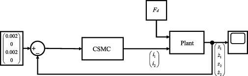
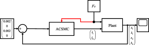
To verify the feasibility of CSMC and ACSMC, simulations were conducted using Matlab-Simulink, Both CSMC and ACSMC employed the same control parameters, which are shown in Table. 1. Figure 3 shows the control diagram used in the simulation of CSMC group, in Fig. 3, the controller is CSMC, which is jointly denoted by Eq. ((3)) and Eq. ((8)). F d denotes the attractive force of the cylindrical electromagnet to the iron disk, which is regarded as a disturbance for the system. Figure 4 shows the control diagram used in the simulation of ACSMC group, in Fig. 4, the controller is ACSMC, which is jointly denoted by Eq. ((3)) and Eq. ((9)), the dashed arrow in Fig. 4 illustrated that ACSMC will be updated with the change of F d , the updated item of ACSMC is the Q shown in Eq. ((9)).
In addition, the following settings and assumptions were used in both groups: (1) As shown in Fig. 5, three kinds of bending loads were employed to comprehensively test the robustness of the controllers. (2) Considering that the two airgaps are prone to get larger after being subjected to bending loads, to mimic this, two positive step disturbances were applied to the two airgaps at 3.5 s and 6.5 s, the one was during the loads action, the other one was after the loads are over. (3) The plant model used in the simulation was the nonlinear model shown in Eq. (8) rather than a linearized plant model. (4) F d exactly acted on the centroid of the levitated object in vertical direction.
Control diagram of CSMC group.
Control diagram of ACSMC group.
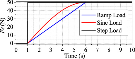
Bending loads in simulations.
Figure 6 shows the simulation result by CSMC under the ramp bending load. As shown in Fig. 6, the airgaps are divergent after the bending load acted. Since all the simulation results by CSMC are divergent regardless of which load is applied, this paper only shows this result of the ramp bending load as an example, the other two sets of results are not presented repeatedly. So, it can be concluded that CSMC cannot cope with the bending loads well.

Simulation result by CSMC under the ramp bending load.
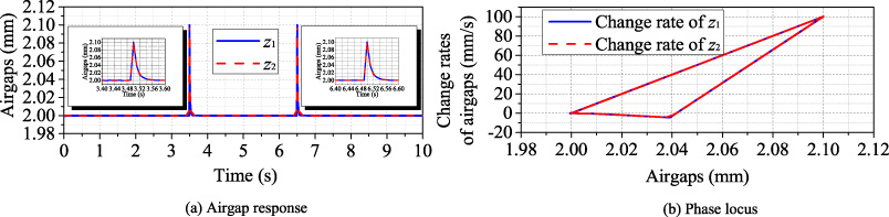
Simulation results by ACSMC under the ramp bending load, sine bending load and step bending load.
Figure 7 shows the simulation results by ACSMC, since the three simulation results under the ramping bending load, the sine bending load and the step bending load are all same, Fig. 7 can represent all three simulation results. As can be seen in Fig. 7(a), the airgaps have almost no chattering and the setting times after the step disturbances are lower than 0.1 s. On the other hand, as can be seen in Fig. 7(b), due to the step disturbances, the trajectory deviates from the sliding surface, but they eventually return to the initial position. i.e., ACSMC performed well in compensating the three kinds of bending load. However, it is not enough to conclude that ACSMC will perform well in the experiment, because it was assumed that the force measured by the force sensor and the force actually acting on the levitated object were exactly identical in the simulation. However, there must be errors between the force measured by the force sensor and the force actually acting on the levitated object. Therefore, as shown in Fig. 8, we measured a set of noise with the force sensor in static, then the data was regarded as force sensor error. With the force sensor error, simulation was conducted again in the same condition, the simulation results are shown in Fig. 9. Since the three simulation results under the ramping bending load, the sine bending load and the step bending load are almost same, Fig. 9 can represent all three simulation results. Comparing Fig. 7 with Fig. 9, it can be found that there is no significant difference between the simulation results with the noise and without the noise except for a slight jitter in the airgaps when the noise involved. To sum up, the simulation results demonstrated that ACSMC is feasible.
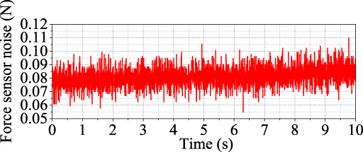
Measured force sensor noise.
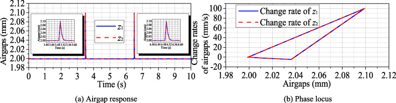
Simulation results by ACSMC under the force sensor noise.
Experimental setup.
Control parameters in the experiment
Experiment results by ACSMC under ramp bending load.

Experiment results by ACSMC under sine bending load.
Experiment results by ACSMC under step bending load.
Finally, an experiment was performed to further validate the feasibility of ACSMC, the control parameters in the experiment is shown in Table. 2. The control diagram illustrated in Fig. 4 was employed in the experiment and F d in the experiment is a ramp force with a rate of about 1 N/s.
Figure 10 presents a system integration diagram and a photography of MLTBD. As shown in Fig. 10(a), the model of the eddy current sensor is HA-80R, which is made by SENTEC corporation. There are two kinds of power amplifier, one is ESCON 50/5, which is made by MAXON corporation, the other one is BPS amplifier, which is made by TAKASAGO, ltd. The model of the force sensor is 9E01-L35, which is made by NEC corporation and has a measuring range of ±50 N. The real-time control system is based on MicroLabBox dSPACE, which is equipped with a software package, i.e., Controldesk, in which user can import a Simulink file, tune control parameters in real-time and collect experiment data. The sampling time of the MicroLabBox dSPACE was set to 0.006 s. As shown in Fig. 10(a), MicroLabBox dSPACE drive the power amplifiers via control voltage, while force sensor and eddy current sensor feed the measuring data to MicroLabBox dSPACE by sensor voltage. In addition, there were two control paths, they were levitation path and bending path respectively. The levitation path was used to ensure the levitation stability while the bending path was used to apply the bending load F d .
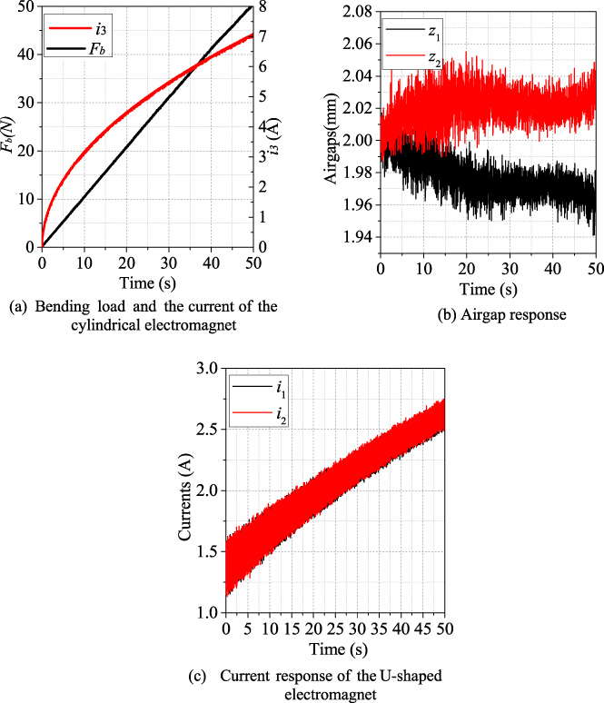
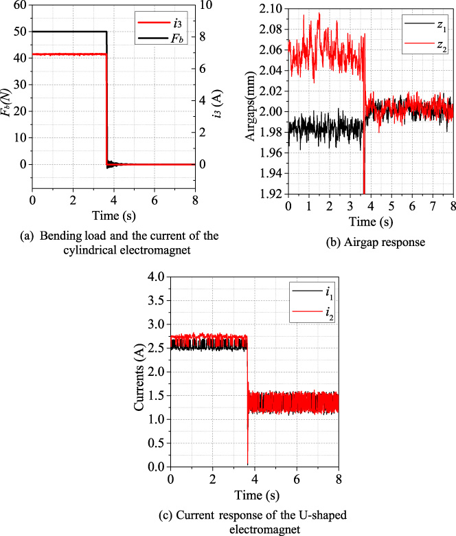
Figure 11 shows the experiment results by ACSMC under a ramp bending load. Figure 11(a) shows the bending load applied to the iron disk and the currents of the cylindrical electromagnets. In addition, Fig. 11(b) and Fig. 11(c) respectively show airgap response and current response for the upper parts. Figure 11(b) indicated that the airgaps slightly changed with the increase of the bending load, but the change was within ±0.05 mm throughout the whole process, which is thought not to have much impact. Figure 11(c) indicated that the current of the U-shaped electromagnet gradually rose to compensate for the bending load. Figure 11(a) indicated that the applicable bending load was up to 50 N. Likewise, Fig. 12 shows the experiment results by ACSMC under a sine bending load. Fig. 12(b) indicated that the airgaps slightly changed with the increase of the bending load, but the change was within ±0.03 mm throughout the whole process, which is thought not to have much impact. Figure 12(c) indicated that the currents of the U-shaped electromagnets gradually rose to compensate for the bending load. Figure 12(a) indicated that the applicable bending load was up to 50 N. Fig 13 shows the experiment results by ACSMC under a step bending load. The step bending load is shown in Fig. 13(a), as shown in Fig. 13(a), the bending load stepped from 50 N to 0 N, which was realized by changing i3 from 6.9 A to 0 A steeply. Fig. 13(b) indicates that the two airgaps changed steeply and finally stabilized at 2 mm, which implies that the levitation was maintained even though the step bending load was applied. In addition, as shown in Fig. 13(c), the currents of the U-shaped electromagnets responded instantaneously to cope with the change. To sum up, ACSMC is effective in compensating for ramp bending load, sine bending load and step bending load.
This paper presents a magnetic levitation three-point bending device, which allow non-contact bending load to be applied to a specimen. This device requires that the levitated object to bear a bending load while it is being levitating, which requires a strong robustness for a control system. Therefore, an adaptive sliding model controller was proposed, i.e., ACSMC. Furthermore, control simulations were conducted to investigate the performances of the controller, simulation results demonstrated that ACSMC has the good performance in compensating for the bending load. Finally, experiments were performed with ACSMC, experiment results demonstrated that ACSMC allows the device to withstand ramp bending load, sine bending load and step bending load up to 50 N.
In this paper, only one material with higher hardness was used in the experiment. In the future, materials with different mechanical properties will be used in experiments, and a force controller will be designed for the cylindrical electromagnet at the bottom.
Footnotes
Acknowledgements
This research is supported by Kochi University of Technology.