
Abstract
Aiming at the problems existing in current electric energy replacement, such as the random energy fluctuation of the power grid, the energy storage of the power grid and the consumption of new energy, electromagnetic coupling heating technology and methods based on power frequency high power is proposed. According to the theory of electromagnetic induction heating, Maxwell’s equations are used to establish a three-dimensional electromagnetic field simulation model, determining the size of the core and the windings, and completing the structural design of the heater. Based on the simulation model of electromagnetic coupling heater, the back electromotive force of the primary winding, the induced current of the secondary winding, the B–H curve field diagram of the core, and the J-field diagram of the secondary winding are analyzed to explore heating efficiency of the heater and verify the correctness of electromagnetic coupling heating mechanism. The relationship between the coupling gap, the number of heat dissipation rings, and the air gap and heating efficiency of the heater was further explored, and the model structure of the heater was optimized according to the variation rules so that heating efficiency of the heater reached more than 99%. The electromagnetic coupling heater achieves high efficiency, cleanliness and low carbon, and power frequency high power, which is of great significance to the renewal of electric heater in the future.
Keywords
Introduction
The electric heating technology at home and abroad has experienced the change of three kinds of heating technology, from resistance heating to electrode boiler, and now electromagnetic induction heating [1]. In modern society, electromagnetic induction heating equipment is widely used in metallurgy, national defense industry and other industrial fields, which makes the percentage of electric energy in energy consumption continuously increase, so that the energy structure can be fully optimized and promote better economic development [2]. The study of electromagnetic induction heating technology is an important stage in the history of electromagnetism [3].
High-frequency electromagnetic induction heating technology refers to the high-frequency alternating current, acting on the metal body, producing eddy current, so that carriers and atoms collide with each other and friction generates heat energy, to achieve high power heating [4]. Electromagnetic induction heating requires the use of high-frequency inverters in which the resonant circuit is formed by the working head and capacitor in series [5,6] or parallel configuration [7]. Therefore, many scholars have started their research by optimizing a certain device. T. Ngo-Phi et al. [8] proposed a voltage-fed three-stage triple-switching PWM rectifier to achieve a high power factor and low current THD. R. Kawashima et al. [9] introduced a high-performance direct power converter from three-phase mains frequency AC to high-frequency AC, which minimizes the number of bidirectional switches and features direct frequency conversion and a wide range of soft-switching. Many scholars develop new techniques or start by optimizing techniques or a certain parameter. O. Lucia et al. [10] proposed a technique that can be used as an effective tool for estimating the magnetic coupling between the coil of an advanced induction heating appliance and the induction heating load. C. Li et al. [11] proposed a new technique of electromagnetic heating molding to make thick or hard metal work pieces easier to form. F. Zhou et al. [12] adopted a new power frequency electric heating method based on the electromagnetic coupling principle to solve problems such as strong electromagnetic interference and the high cost of high-frequency electromagnetic induction heating equipment. X. Wu et al. [13] proposed an electromagnetic-thermal coupling analysis method for the armature component of an electromagnetic vibrator by combining infrared thermal imaging and the finite element method. E. Plumed et al. [14] used three inductors combined into a set of electromagnetic coupling heating system, which was capable of heating two magnetically unrelated ferromagnetic loads placed on different horizontal planes.
However, the problem of the high failure rate of electromagnetic heating has not been well solved. In addition, the analysis model of electromagnetic heating system has always been around in linear research, so it is difficult to use the existing simulation model to conduct a nonlinear simulation of the actual system, resulting in low precision of the design model [15].
To overcome the shortcomings of existing technology, this paper proposes electromagnetic coupling heating technology and method based on power frequency high power. A three-dimensional electromagnetic field simulation model was established to complete the structural design of power frequency high power electromagnetic coupling heater. The model structure of the heater was optimized by analyzing the magnetic field distribution and heat source distribution and exploring the influencing factors and the variation rules of heating efficiency of the electromagnetic coupling heater. The electromagnetic coupling heater is mainly used for urban central heating and centralized or distributed thermal energy storage in the power grid, which can effectively resolve the problems of random energy fluctuation in the power grid, new energy consumption and electrical energy substitution.
The principle and model of the electromagnetic coupling heater
The basic structure of the electromagnetic coupling heater
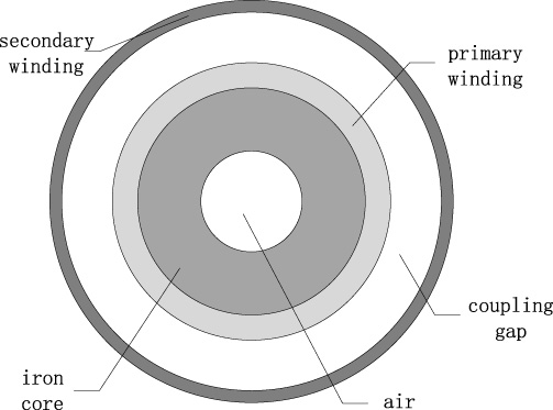
The electromagnetic coupling heater studied in this paper evolved from the transformer structure, which is composed of the core, Y-type magnetic column, the primary winding, the coupling gap and the secondary winding. The primary winding is wound on the surface of the core, and the core connects to Y-type magnetic column. The coupling gap is between the primary winding and the secondary winding. The basic structure of the electromagnetic coupling heater is shown in Fig. 1.
The electromagnetic coupling heater of power frequency high power adopts the principle of shorting secondary side of the transformer to generate a larger current on the secondary side of the transducer, which in turn generates a larger thermal power. To describe its principle more simply and clearly, single-phase transformers are explained as an example. The single-phase transformer has two coils wound on a closed the core, the coil connected to the power supply is called the primary winding, and the coil connected to the load is called the secondary winding. A schematic diagram of the transformer is shown in Fig. 2:

The basic structure of the electromagnetic coupling heater.
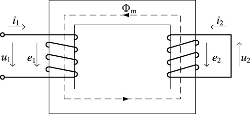
The transformer schematic diagram.
Since this paper uses ANSYS/Maxwell software, the final equations and descriptions used in that software are given as follows:
The complete statement of the problem of a definite solution of the transient field can be summed up as the above equation, under the given initial conditions, making the solutions of
In the three-dimensional electromagnetic field of the heater, the primary winding needs to be loaded with current when the voltage source or current source can be invoked as the model excitation source. In the actual analysis, the winding is divided into stranded winding and solid winding, where the stranded winding does not consider the eddy current distribution, and the current density in the stranded winding is considered to be completely uniform, while the solid winding needs to calculate its skin effect.
According to the technical requirements of induction heating, the electromagnetic heating equipment is designed, a simulation model based on 3D finite element theory is established to accurately analyze heating efficiency and magnetic field distribution, and the simulation calculation is carried out for different working conditions.
The Size confirmation of the electromagnetic coupling heater
This paper designs a kind of power frequency high power electromagnetic coupling heater, and the design requirements according to the actual situation are as follows:
The rated capacity of the electromagnetic coupling heater is not less than 180 kW. The rated voltage of the electromagnetic coupling heater meets (380 ± 2.5%) V. The volume of the electromagnetic coupling heater is not less than 1 m3.
The key to design of the electromagnetic coupling heater is to determine the structural dimensions and operating parameters, and the rationality of each data directly affects the performance of the heaters.
Single-phase capacity per column:
The core diameter:
Cross-sectional area of the core:
Effective cross-sectional area of the core:
Initial calculation of voltage per turn:
Number of turns of the primary winding:
Voltage of the secondary winding:
Effective value of the primary winding current:
Peak current of the primary winding wire:
Effective value of the secondary winding current:
This section focuses on the size and structure design of the 380 V/180 kW electromagnetic coupling heater, three-phase rated capacity S N is 180 kW, the direct use of a three-phase frequency power supply, the frequency f is 50 Hz, engineering experience in the core diameter coefficient K D is 56, the core space filling factor K SF is 0.99, the core of the lamination coefficient K FD is 0.98, and the flux density B m1 is 1.8. The data calculated by the above formula are shown in Table 1.
The operating parameters of the heater at 380 V/180 kW
The core adopts a hollow type to increase the heat dissipation effect and avoid the core temperature rising due to the core loss, which reduces the working performance of the core. To ensure that the effective cross-sectional area of the core is 194.97 mm2, that is, the core diameter D is 164 mm, and to improve heating efficiency of the electromagnetic coupling heater, the primary winding is selected with a cross-sectional area of 2.5 mm2 and a wire diameter of 1.8 mm. The parameters are calculated as shown in Table 2.
The structural dimensions of the 380 V/180 kW heater
As the secondary side induced voltage is 3.23 V, the voltage value is very low, and the insulation level requirements are extremely low, which is conducive to the safety of the device, the induced current of secondary side reaches the kiloamp level, which will generate large eddy current losses in the secondary winding, which is used to heat. According to the experience of wire diameter of the winding, the selection of conductor is shown in Table 3.
The comparison table of winding wire diameter empirical coefficients
The primary winding of high power electromagnetic coupling heater is made of copper wire wound on the outer surface of the core. The core is a concentric hollow cylindrical structure, and the material is DW310_35. This type of silicon steel sheet has the advantages of low iron loss, high magnetic flux density in a strong magnetic field, smooth surface, even thickness and so on.
Generally, with increasing silicon content, the iron loss, impact and magnetic flux density decrease, and the hardness increases. Therefore, the DW310_35 silicon steel sheet is the best choice for the design of this paper [16]. The B–H characteristic curve of DW310_35 is shown in Fig. 3.
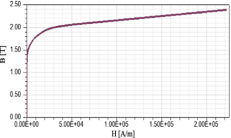
The B–H characteristics of the core material DW310_35.
The core is hollow, and three-phase core is connected by a Y-shaped magnetic circuit to form a closed circuit. This structure is modeled after three-phase core of the core-type transformer, since the vector sum of the fluxes of the ABC three-phase core is zero, the intermediate connecting core is eliminated, which saves materials and reduces costs and the complexity of the model.
The secondary winding, that is the water tank of the electromagnetic coupling heater, and the water tank is selected as the cylindrical water tank, the axisymmetric structure makes the simulation calculation simple, and the cylindrical structure is similar to the water tank structure in the actual project, which has practical application value. The water tank material is steel_1010, which has good plasticity and toughness, is easily formed by hot and cold processing, has excellent weldability, low carbon content and excellent magnetic conductivity. The B–H characteristic curve of the steel_1010 material is shown in Fig. 4.
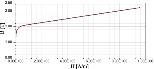
The B–H characteristic curve of the material steel_1010.
The capacity of the electromagnetic coupling heater is 180 kW, which is converted to the actual project, and the storage volume of the water tank is about 0.8 m3 after pressure calculation, the tank wall thickness is set to 5 mm for the appropriate thickness, which not only to meet the mechanical stress but also to meet the performance indicators of magnetic conductivity. The coupling gap between the primary winding and the secondary winding is 30 mm.
The 3D finite element analysis model of the electromagnetic coupling heater is established using ANSYS/Maxwell software, and the 3D finite element analysis model of the electromagnetic coupling heater is shown in Fig. 5.
The 3D finite element analysis model of the electromagnetic coupling heater.
In Maxwell’s three-dimensional electromagnetic field analysis, the mesh units of coil and air are adaptively divided. In the heating process, the primary winding coil and the secondary winding coil surface will produce a skin effect, the skin effect layer needs to be encrypted subdivide, and the mesh subdivision under the skin effect layer can be relatively sparse.
For the different parts of the electromagnetic coupling heater, by setting the model in ANSYS/Assign Mesh Operation/Inside Selection/Length Based module. The section accuracy between the core and the primary and secondary windings is set as a unit of 10 mm, decreasing from 200 mm to 30 mm, The section accuracy of the solution region is set as a unit of 10 mm, decreasing from 200 mm to 30 mm successively, After simulation, the software calculation time increases as the profile accuracy decreases. When the profile accuracy of the model is above 50 mm, the profile accuracy has a large impact on the model data results, and when the profile accuracy of the model is below 50 mm, the impact of the profile accuracy on the model data results is small and can be ignored. After several simulations, when the accuracy of regional division is less than 100 mm, it has little influence on this simulation, which is completely sufficient. A suitable dissection accuracy between the primary winding and the secondary winding is 50 mm, 50 mm for the core, and 100 mm for the solution area. The overall dissection of the electromagnetic coupling heater and the local dissection of the primary winding and the core are shown in Figs 6 and 7.

Overall sectional view of the electromagnetic coupling heater.
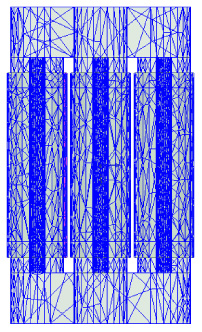
The sectional view of the core and the primary winding of the electromagnetic coupling heater.
Since the simulation model of the electromagnetic coupling heater in this paper is a 3D transient model structure, to analyze the magnetic field distribution of the secondary winding when a three-phase alternating current is added to the primary winding more clearly and comprehensively, the entire model is fully dissected, and the whole model is selected for calculation. The primary winding of the 380 V/180 kW electromagnetic coupling heater is fed with a three-phase alternating current source with a peak value of 386 A, where the phases of the three currents differ by 120 ° from each other, and the solver is selected in a three-dimensional coordinate system as a transient field solver in ANSYS/Maxwell. In the selection of boundary conditions, considering the tangential and normal directions of the field quantities at the intersection of different media, the default boundary condition in the software system is selected, that is, the natural boundary condition.
According to the established finite element simulation model of the electromagnetic coupling heater, under the premise that the primary side voltage level is 380 V and the rated capacity is 180 kW, a comprehensive analysis of the back electromotive force of the primary winding, the loss of the primary winding, the induced voltage of the secondary winding, the loss of the secondary winding and the magnetic field distribution of each part is performed.
Three-phase alternating current and the back electromotive force of the primary winding
The primary winding inputs a three-phase sinusoidal alternating current excitation source with a peak value of 386 A and an ABC three-phase current source phase difference of 120°. The input current through the coil produces an alternating voltage in the primary winding, and the input current and the back electromotive force of the primary winding are shown in Figs 8 and 9.

A three-phase alternating current input to the primary winding.

Three-phase back electromotive force of the primary winding.
From the image, the peak value of the back electromotive force of the primary winding is between 310 V and 320 V, and the peak of the AC power with an effective value of 220 V is approximately 311 V, so the voltage output waveform meets the 380 V voltage level required by the unequal constraint.
The alternating current induces an alternating flux φ in the core, and the primary winding and the secondary winding are connected together in a closed circuit of the core, so when the flux φ passes through the secondary winding, an alternating current is generated in the secondary winding, that is, the induced current of the secondary side, and at the same time, the induced electric potential is generated in the secondary winding, that is, the secondary side induced voltage, as shown in Figs 10 and 11.
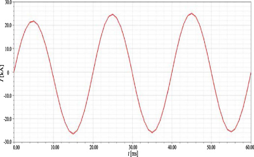
The induced current of the secondary winding.
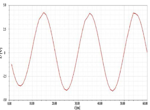
The induced voltage of the secondary winding.
As seen from Fig. 10, the effective value of the induction current of the secondary side is approximately 22 kA, As is known from the Poynting theorem that a large output power will be generated on the secondary side for heating. The effective value of the induction voltage of the secondary side is approximately 4 V, and the electromagnetic coupling heater is used to heat the heated liquid, three-phase alternating power supply provides a direct power supply to automatically realize the high-voltage conversion. At the same time, the insulation level requirement is extremely low, which guarantees the safety of maintenance and testing personnel and users and greatly improves the reliability of the device.
The core material is DW310_35, whose knee point is between 1.8 T and 1.9 T, and the magnetic inductance distribution of the core of the electromagnetic coupling heater is shown in Fig. 12.
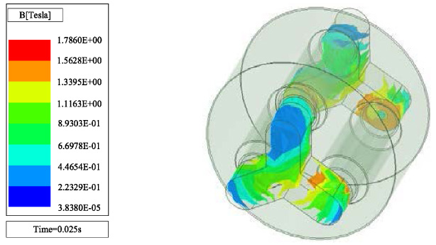
B-field diagram of the magnetic induction of the core at 25 ms.
Figure 12 shows that when the magnetic flux density is at the peak current, the peak value of the C phase magnetic flux density reaches 1.786 T, which is close to the optimal magnetic flux density of the silicon steel DW310_35, indicating that the magnetization curve of the core is approximately linear under this magnetic flux density. In this case, the core has the best working condition.
The H-field of the magnetic field intensity of the electromagnetic coupling heater is shown in Fig. 13.
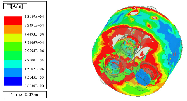
H-field diagram of the electromagnetic coupling heater at 25 ms.
From the figure, we can see the vector distribution of magnetic field lines inside the electromagnetic coupling heater after the alternating three-phase current is connected.
The current density J-field diagram of the electromagnetic coupling heater is shown in Fig. 14.
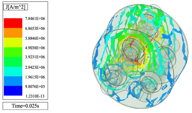
The current density J-field of the electromagnetic coupling heater at 25 ms.
As seen from the figure, at 25 ms, the current of the primary winding in phase A is at its peak, and the electric density induced by the primary winding in the secondary winding is vortex-shaped and concentrated in the coupling area of the primary winding and secondary winding in phase A. The current density is as high as 7.8 MA/m3.
The secondary winding produces a great induction current, which in turn produces a large thermal power, compared with the large current induced in the secondary winding, the primary winding current is smaller, other losses are not considered, and the thermal efficiency is high. The loss of the primary winding and the secondary winding can be solved by the Poynting theorem vector integration formula, as shown in Formula (13).
The loss of the primary winding and the loss of the secondary winding calculated by ANSYS/Maxwell is shown in Figs 15 and 16:

The loss of the primary winding.
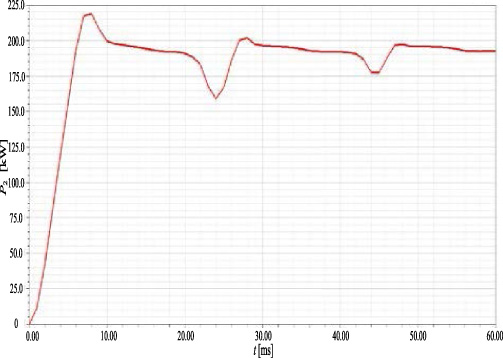
The loss of the secondary winding.
As seen from the figure, the average value of the loss of the primary winding is 1.683 kW, the loss of the secondary winding is finally stabilized at 180 kW, and the calculation formula of heating efficiency:
In the formula:
P 1: The loss of the primary winding, kW.
P 2: The loss of the secondary winding, kW.
𝜂: heating efficiency.
According to the calculation of Formula (14), heating efficiency of the electromagnetic coupling heater is as high as 99.065%, the use of the electromagnetic coupling heater achieves effective isolation of the power supply and heating parts, and the heating energy is completely supplied to the heated liquid. The 380 V/180 kW electromagnetic coupling heater meets the design requirements and verifies the correctness of the electromagnetically coupled heat generation mechanism.
The heating mechanism was combined with the simulation model of the 380 V/180 kW electromagnetic coupling heater. Under the requirement of power quality design, the influences of the coupling gap, the number of heat dissipation rings and the air gap on heating efficiency of the electromagnetic coupling heater were analyzed to provide data support for further optimization of the simulation model.
Analysis of the influence of the coupling gap on heating efficiency
The electromagnetic coupling gap is the induction distance between the primary winding and the secondary winding, which is also the magnetoelectric conversion distance of the electromagnetic coupling heater, and the size of the electromagnetic coupling distance directly affects heating efficiency of the electromagnetic coupling heater. Through multiple groups of simulation experiments, this section will find the optimal coupling gap to optimize the structure the 380 V/180 kW electromagnetic coupling heater and improve heating efficiency of the electromagnetic coupling heater. The coupling gap of the electromagnetic coupling heater is shown in Fig. 17.
The coupling gap of the electromagnetic coupling heater.
Based on the simulation model of the 380 V/180 kW electromagnetic coupling heater, the parts in the figure are the air, the core, the primary winding, the coupling gap and the secondary winding from inside to outside. By changing the coupling spacing to find the best coupling gap, the model is finally optimized. with the coupling gap as the independent variable and heating efficiency of the electromagnetic coupling heater as the dependent variable, the coupling gap is selected from 0 mm to 60 mm, and the experimental sampling data are shown in Table 4.
Influence of the coupling gap on heating efficiency
The data in Table 4 show that heating efficiency reaches more than 90% when the coupling gap is between 10 and 35 mm, and the coupling gap between 19 and 22 mm achieves a heating efficiency of 99%. To illustrate the effect of the coupling gap on heating efficiency directly, the data in the table are drawn into a broken line graph, and a mathematical method is used to perform a third-order fitting curve, as shown in Fig. 18:
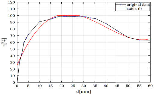
Broken line graph and third-order fitting curve.
In the figure, d represents the coupling gap, and it can be seen intuitively from Fig. 18 that the optimal coupling gap for the heating generation efficiency is from 15 mm to 35 mm, the coupling gap of the electromagnetic coupling heater is approximately 20 mm, and heating efficiency is the highest, which provides data support for the optimal design of the electromagnetic coupling heater.
The essence of installing the heat dissipation ring is to increase the electromagnetic coupling area between the secondary winding and the primary winding and then increase the contact area with the heated liquid to improve heating efficiency. For the number of heat dissipation rings at odd times, the material of the heat dissipation ring is Steel_1010, the thickness is 5 mm, the inner diameter is 164 mm, and the outer diameter is 214 mm. Through several sets of simulation experiments, this section analyzes the effect of the number of heat dissipation rings on heating efficiency and summarizes the change law of heating efficiency by changing the number of heat sink rings to lay the foundation for the optimal design of the electromagnetic coupling heater.
Since the electromagnetic coupling between the primary winding and the secondary winding mainly occurs on the outer wall of the coupling gap, the heat dissipation ring is installed on the outer wall of the coupling gap to increase the heating area of the heated liquid and the water tank, which improves heating efficiency. To better describe the structure of the heat dissipation ring, this section describes the heat dissipation ring installed in one group and three groups, as shown in Figs 19 and 20:
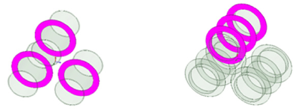
Schematic diagram of heat dissipation ring.

Schematic diagram of installing the heat dissipation ring.
Based on the simulation model of the electromagnetic coupling heater, the coil turns of this model are 66 turns, and the outer wall of the coupling gap is installed with heat dissipation ring of groups 1, 3, 5, 7, and 9, The simulation results are compared and analyzed, and the simulation data is shown in Table 5.
The influence of the number of dissipation rings on the loss
As seen from Table 5, the number of heat dissipation rings is represented by n under the same coil turns, and the loss of the primary winding is almost unchanged as the number of heat dissipation rings increases, which illustrates that the loss of the primary winding is not related to the number of heat dissipation rings but only to the number of turns of the winding coil, while the loss of the secondary winding, that is, the output power, is reduced. A summary of the secondary loss trends for different numbers of heat dissipation rings is shown in Fig. 21.
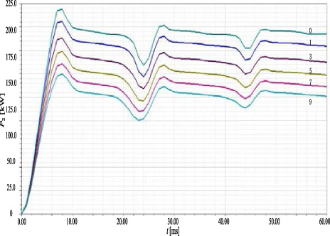
The influence of the number of heat dissipation rings on the secondary winding loss.
As the number of heat dissipation rings increases, the trend of heating efficiency of the heater is shown in Fig. 22:
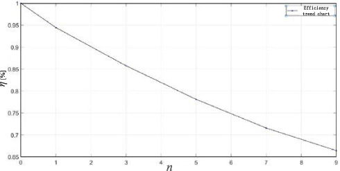
The influence of the number of heat dissipation rings on heating efficiency.
The curves in Fig. 22 show more intuitively that as the number of heat dissipation rings increases, the output power decreases and heating efficiency decreases. The number of coil turns of the primary winding is adjusted so that the simulation output of the 380 V/180 kW electromagnetic coupling heater meets the back electromotive force of the primary winding of 311 V and the secondary loss of 180 kW, at the same time, the magnetic field distribution of each part of the electromagnetic coupling heater is analyzed, under the premise of satisfying the power quality and target capacity, since the change of the number the heat dissipation rings has no effect on the primary loss but has a great influence on the secondary loss, we can analyze the influence of the heat dissipation ring on heating efficiency and the influence of the number of heat dissipation rings on the second loss in this method, which is shown in Table 6 after extensive simulation experiments.
The influence of the number of heat dissipation rings on the measurement loss
Table 6 shows that with the increase in the number of heat dissipation rings, the primary winding loss changes very little, and the secondary loss increases from 180.6 kW to 280.7 kW, a change of 100.1 kW, which significantly increases the heating power. The calculated heating efficiency is shown in Table 7.
The corresponding relationship between the number of heat dissipation rings and heating efficiency
The air gap described in this section separates the front and rear Y-shaped magnetic columns connected with the ABC three-phase core from three-phase core. A schematic diagram of the air gap is shown in Fig. 23.
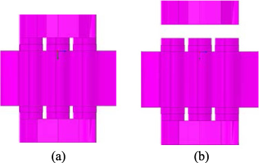
The schematic diagram of the air gap. (a) Normal operation (b) Air gap Operation.
Figure 23(a) shows the structural connection of the electromagnetic coupling heater in normal operation, and Fig. 23(b) shows a schematic diagram of the air gap of Y-shaped magnetic column separated from three-phase core, the distribution of magnetic lines of force in the magnetic field is dynamically changed by the adjustment of the air gap.
Among them, the simulation data of the electromagnetic coupling gap δ are shown in Table 8.
The influence of flux leakage spacing on loss
The closed connected flux path becomes an open path, there is a gap between Y-post and three-phase core, and the flux leakage increases. In this section, the number of core turns is 66, and the number of heat dissipation rings is 9. By adjusting the spacing between the front and rear Y-paths and three-phase core columns, simulation experiments are conducted to analyze the influence of different air gaps on the primary loss and secondary loss of the electromagnetic coupling heater and to calculate the influence of different coupling gaps on heating efficiency.
To summarize the variation law corresponding more intuitively to different air gaps and output powers, the secondary loss comparison and trend of the electromagnetic coupling heater with different air gap spacings are shown in Figs 24 and 25.
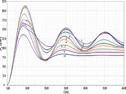
Comparison of the loss of the secondary winding at different spacings.
In Fig. 24, curves L1 to L10 correspond to the air gap from 0 mm to 100 mm, from the simulation data in Table 8 and the comparison chart of secondary loss in Fig. 24, the primary loss of the electromagnetic coupling heater is basically stable between 1.48 and 1.50 kW by adjusting the spacing of the air gap between Y-shaped magnetic column and three-phase core, but the secondary loss, that is, the output power of the water tank, which changes significantly from 122.8 kW to 80.09 kW, and the power adjustment range is further expanded.

The loss trend of the secondary winding at different spacings.
From the secondary loss trend in Fig. 25, the output power is initially 120 kW and eventually stabilizes at 80 kW, the power change rate of the air gap is large in the range of 1–30 mm, the change rate decreases in the range of 30–50 mm, and the variation rate is very small in the range of 50–100 mm, which indicates that the best effect is achieved by adjusting the air gap in the range of 1–30 mm, and heating efficiency is shown in Table 9.
Different spacing corresponds to heating efficiency
The most extreme case is considered here, where the upper and lower Y-posts of the electromagnetic coupling heater are placed at infinity of three-phase core column, that is, the Y-shaped magnetic column is removed, and the secondary winding loss is still calculated as 80 kW. It can be inferred that the model has a control role in regulating the output power, while the primary loss tends to be stable, so it can be concluded that heating efficiency of the electromagnetic coupling heater can be adjusted by changing the spacing of the air gap between Y-shaped magnetic column and three-phase core.
In this paper, electromagnetic coupling heating technology and methods based on power frequency high power is proposed, theoretical derivation, structure design and simulation analysis of the 380 V/180 kW electromagnetic coupling heater is carried out to verify the correctness of the electromagnetic coupling heater mechanism and to optimize the electromagnetic coupling heater. The main conclusions of this paper are as follows:
The core and winding size are determined, the structural design and operating parameters of power frequency high power electromagnetic coupling heater are analyzed, and the design of the 380 V/180 kW electromagnetic coupling heater is determined. The finite element model of power frequency high power electromagnetic coupling heater is established, and the back electromotive force of the primary winding, the induced current of the secondary winding, the B–H curve field diagram of the core, and J-field diagram of the secondary winding are analyzed to verify the mechanism of the electromagnetic coupling heater. On the premise of meeting the core material of unsaturated, the optimum heating efficiency of the electromagnetic coupling heater is calculated. Analysis of influencing factors of the electromagnetic coupling heater on heating efficiency to determine the relationship between the gap spacing, the number of heat dissipation rings, the air gap and heating efficiency and its variation law. The results show that the optimal coupling gap for heating efficiency is 15 mm to 35 mm, the optimal number of heat dissipation rings for heating efficiency is 5 to 9, the optimal magnetic flux leakage gap is 0 mm to 100 mm, and heating efficiency of the 380 V/180 kW electromagnetic coupling heater is more than 99%.
After theoretical analysis and simulation calculation, the electromagnetic coupling heater designed in this paper solves the problems of high energy consumption, low power and electromagnetic radiation of the current electromagnetic heating technology and achieves high efficiency, cleanliness and low carbon and power frequency high power of heater, which is of great significance to the renewal of electric heater in the future.