
Abstract
Because of growing demand in the aircraft industry, research is being conducted around the world to reduce CO2 emissions by electrifying aircraft. The authors are studying a non-contact hybrid aircraft brake that combines an eddy current brake and a magnetorheological fluid brake. This paper presents a basic study of braking and regenerative torque using an axial gap type eddy current brake. The result as that a maximum braking torque of 51.3 mNm was obtained with a three-phase AC power supply when the speed of the conductor disc was 2,000 rpm, the current was 3 A, and the frequency was 10 Hz in the CW direction. The maximum regenerative torque was 48 mNm when the speed of the conductor disc was 2,000 rpm, the current was 3 A, and the frequency was 10 Hz in the CCW direction.
Introduction
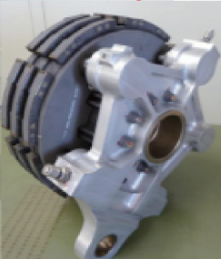
Currently, the multiple disc brakes shown in Fig. 1 are mainly used as axle brakes on jet airliners. The rotor discs are fixed to the wheel and rotate with the wheel, and the stator discs, which are attached to the leg structure and do not rotate, are placed in an alternating arrangement, and these discs are hydraulically brought into close contact as necessary to obtain braking force through friction. Steel has been used for the discs, but more recently carbon fiber reinforced carbon composite (C/C composite), which is lighter and has a longer service life, is being used. It is lightweight because its density is 1/4 that of steel, and it features high specific heat and thermal conductivity, and high heat resistance. In addition, when compared with steel, C/C composite is 40% lighter and has a three to five times longer service life, and is used in many jet airliners. However, because braking force is obtained from the friction generated by the discs making contact with each other to stop the aircraft, the discs need to be regularly maintained and replaced as they wear out. To solve this problem, the authors study non-contact hybrid brakes for aircraft axles that combine an eddy current brake (ECB) and a magnetorheological fluid brake (MRB). Among these, this paper describes the ECB [1–3].
Unlike conventional disc brakes, ECBs are non-contact brakes. A magnetic field is applied externally to the rotating conductor disc to generate eddy currents on the disc surface to produce braking force, while dissipating the kinetic energy of the rotating disc outward as thermal energy. There are two main advantages to replacing existing disc brakes with ECBs. First, since they are a non-contact type they eliminate disc wear, improving maintainability because disc replacement is not required. Second, the electronic control eliminates the need for a hydraulic mechanism, and the reduction in the number of moving parts is expected to improve reliability, reduce size, and reduce weight. In addition, the electronic control system can be easily applied to the future electrification of aircraft. However, the braking force of an ECB is lower than that of a conventional disc brake, and the heat generated by the disc causes decreased conductivity and a decreased braking force.
C/C composite brake.
In this study, the goal is regenerative braking using an axial gap type eddy current brake, and as a preliminary step, a basic study of the torque applied during braking and its regenerative capabilities was conducted. Compared to the previous study, the distance between adjacent yokes is short, and the 6-pole pair makes the rotating magnetic field closer to a sinusoidal wave. Moreover, the back yokes are not independent and are magnetically connected as one yoke. So, high torque density is expected. The objectives of this study are as follows. Measure the braking and regenerative torques of a single material disc made of Cu and Al when a three-phase AC is externally applied to the disc’s rotation axis clockwise and counter-clockwise by means of an excitation coil. From these results, examine the feasibility of regenerative braking using an axial gap type eddy current brake.
In this chapter, we will describe the principle of the ECBs that we used within this study. First, the electromotive force (EMF) is generated on the disc by Faraday’s law of induction when the magnetic flux is applied to a rotating conductive disc by Fleming’s left hand rule. Next, the eddy current is generated on the surface of the disc by the EMF which acts to prevent the magnetic flux change on the disc by Lenz’s law. Then, the braking force acts in the opposite direction of the disc’s rotation by Fleming’s right hand rule. The ECB uses these phenomena to produce braking torque. Figure 2 is a parameter diagram of the axial gap type ECB used in this experiment. The theoretical equation for the ECB’s brake torque is given by the following Eq. (1):
a: Maximum width of yoke [m]. b: Vertical width of yoke [m]. d: Thickness of conductor disc [m]. lgap: Gap length between disc and excitation head [m]. r: Radius of conductor disc [m] B: Magnetic flux density [T]. S: Cross section area of yoke [m2]. R: Effective radius of disc [m]. σ: Disc conductivity [S/m].
Tdisc is the braking torque that affects the conductor disc.
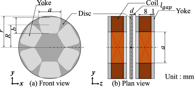
Axial gap type ECB parameter diagram.
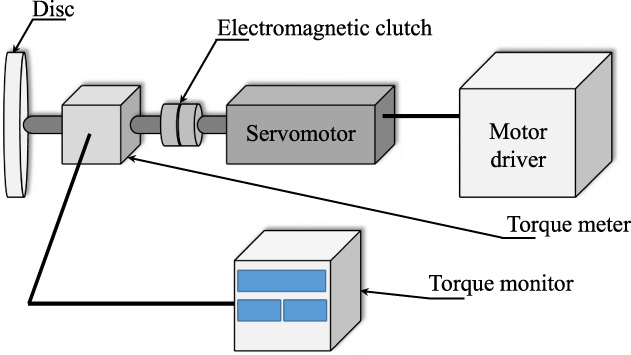
In this chapter, we will describe the experimental equipment used in this study. Figure 3 shows a three-dimensional model of the cross-sectional view of the axial gap type ECB used in this experiment. The whole photograph of the experimental equipment and that block diagram show are shown in Fig. 4 and Fig. 5, respectively. In this experiment, 6 pairs of coils with φ = 0.5 mm Cu wire wound 50 times were manufactured and mounted to sandwich the conductive disc. The thickness of the disc was 1 mm, and the gap between the coils was 2 mm. In the experimental equipment, the AC servo motor (ORIENTAL MOTOR: NXM410A) is rotated at an arbitrary speed by the motor driver (ORIENTAL MOTOR: NXD20-A), and via the electromagnetic clutch (OGURA C LUTCH: AMC10E) and torque meter (UNIPULSE: UTM II-0.5 Nm). Then, the conductor disc which was fixed to the shaft of the axial gap type excitation head (35H300) and sandwiched between the excitation coils was rotated. The value measured by the torque meter when magnetic flux was applied to the disc was read by the torque monitor (UNIPULSE: TM301). Results are outlined in Table 1 below.
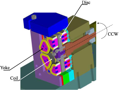
Three-dimensional model of a cross-section of an axial gap type ECB.
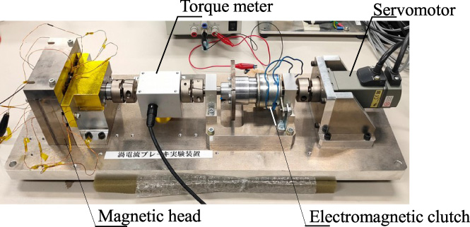
Experimental equipment of an axial gap type ECB.
Block diagram of the experimental equipment.
Detailed conditions
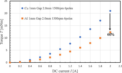
Current-torque characteristics with DC applied.
In this study, Cu and Al were selected as the materials for the conductor disc. This is because the conductivity of the disc affects braking torque. This is also to compare Cu, which is generally easily available and has high conductivity, with Al, which is lighter than Cu, is easily available, and has the next highest conductivity.
In this chapter, to examine the effect of the disc material on braking torque, we will describe the braking torque characteristics from DC excitation, and single-phase AC excitation when using either a Cu disc or an Al disc.
DC excitation
The conductor disc was rotated at 1,500 rpm using an AC servomotor. After the rotation stabilizes, the torque monitor display was calibrated to eliminate external factors such as friction, inertia, and air resistance, and to accurately measure the brake torque of the ECB. A DC voltage source (KIKUSUI ELECTRONICS: PAN110-10A) was connected to the coil of the excitation head of the ECB, and the coils were connected in series so that the north and south poles alternated. DC was applied to the coil from 0 A to 2 A at intervals of 0.2 A, and the brake torque was measured with a torque meter. This was done with both Cu and Al discs. Figure 6 shows the current-torque characteristics. From the experiment, the braking torque of both the Cu disc and the Al disc increased in proportion to the current. This is because the braking torque is proportional to the square of the magnetic flux density. The magnetic flux density is expressed using the following equations.
Also comparing the Cu disc and the Al disc, the torque of the Al disc was about 60% that of the Cu disc. This is because when the conductivity of the Cu disc is 100%, the conductivity of the Al disc is 61.7%, and the influence of this conductivity transfers onto the brake torque. Since Al has a specific density of about 1/3 that of Cu, it is suitable as an aircraft material where weight reduction is a factor, and when the specific gravity is the same as that of Cu disc, it can be expected to increase torque by more than double. However, from previous studies, when AC was applied on thicker discs, it is known that the eddy current induced in the disc increases, and works to cancel the magnetic flux applied to the disc, resulting in a decrease in braking torque [7,8].
The conductor disc was rotated at 1,500 rpm using an AC servo motor, and the torque monitor display was calibrated. An AC voltage source (KIKUSUI ELECTRONICS: PCR500LE) was connected to the coil of the excitation head of the ECB, and was connected in series in the same manner as above. The current applied to the coil was fixed at 2 A, the frequency was changed every 1 Hz from 1 Hz to 10 Hz, and every 10 Hz from 10 Hz to 50 Hz, and the brake torque was measured with a torque meter. This was done with both a Cu disc and an Al disc. Figure 7 shows the frequency-torque characteristics. The result is that braking torque decreased as the frequency increased. In particular, a decrease in braking torque of about 6% was observed every 10 Hz. This is because when an AC magnetic field is applied to a rotating conductor disc, the eddy current induced in the disc acts to reduce the gap magnetic flux density of the excitation head. This means that as the frequency increases, the magnetic field changes over time, the electrical resistance of the disc decreases, and the eddy current induced on the conductor disc increases, further reducing the gap magnetic flux density. As the gap magnetic flux density decreases, so does the braking torque affected by the magnetic flux density [8].
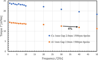
Frequency-torque characteristics with single-phase AC applied.
In this chapter, we describe the experiments conducted using Cu discs and Al discs to examine the basic characteristics of the braking torque of the axial gap type ECB through three-phase AC excitation.
Experimental method
Using an AC servomotor, the conductor disc was rotated counterclockwise (CCW) at 500 rpm, 1,000 rpm, 1,500 rpm, and 2,000 rpm when viewed from the axis of rotation. After rotation stabilized, the torque monitor display was calibrated to eliminate external factors and accurately measure ECB brake torque. A power supply environment simulator (NF CORPO-RATION: ES 2000U) was connected to the coil of the excitation head of the ECB so as to be U, V and W. In addition, the rotating magnetic fields were connected so that they acted both clockwise (CW) and counterclockwise. A current was applied to the coil at 1 A intervals from 0 A to 3 A, the frequency was changed at 10 Hz intervals from 10 Hz to 100 Hz, and at 20 Hz intervals from 100 Hz to 300 Hz, and the resulting brake torque was measured with a torque meter. In addition, since the current output from the power supply environment simulator has an error associated with the current applied to the coil, a power meter (HIOKI: PW3390) was connected to U, V and W to calibrate the current. This was done with both a Cu disc and an Al disc.
Experimental result
The frequency-torque characteristics are shown in Fig. 8–Fig. 11. With 0 Hz as the boundary, the left side represents the rotating magnetic field in the CW direction, and the right side represents the rotating magnetic field in the CCW direction.
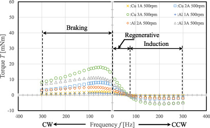
Torque dependence on varying frequencies at a disc rotating at 500 rpm.
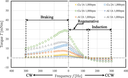
Torque dependence on varying frequencies at a disc rotating at 1,000 rpm.
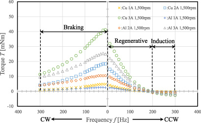
Torque dependence on varying frequencies at a disc rotating at 1,500 rpm.
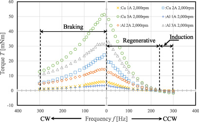
Torque dependence on varying frequencies at a disc rotating at 2,000 rpm.
From the graph, the maximum braking torque occurred when a rotating magnetic field was applied in the CW direction at each rotation speed, and then the braking torque decreased as the frequency increased. In addition, the braking torque increased as the applied current increased. This is because brake torque is affected by the magnetic flux density, which is proportional to the current. Also, the braking torque grew as the frequency lowered, and the braking torque shrank as the frequency rose [8].
When a current was applied in the CCW direction, the braking torque became larger with faster disc rotation. This is because the braking torque increases in proportion to the rotational speed of the conductor disc and the relative speed of the rotating magnetic field. The brake torque is greatest when the rotation speed of the conductor disc is high and the frequency of the rotating magnetic field is low. The brake torque does reach 0 or lower at certain frequencies. This indicates that when the brake torque is 0, the conductor disc and the rotating magnetic field are at the same speed. Beyond that, the braking torque that reached the negative region began increasing again. This is because the eddy current induced in the conductor disc reduces the magnetic flux of the exciting head just as it does in the CW direction [9].
In this study, we studied the basic characteristics of braking and regenerative braking torque when a three-phase AC is applied to an axial gap type eddy current brake. As a result, this eddy current brake has to be improved to obtain the required torque when it is applied as a brake for aircraft axles, however, we think that it can be used as a regenerative brake. The results are summarized below. Using the DC excitation method, the torque increased with an increase in current in both the Cu disc and the Al disc. This is because the brake torque is proportional to the magnetic flux density. When comparing the Cu disc and the Al disc, the Al disc obtained a braking torque of about 60% of that of the Cu disc. This is because when the conductivity of Cu is 100%, the conductivity of Al is about 60%, which when appears in the braking torque affected by this conductivity. Al has a specific density of about 1/3 of Cu, and when the specific gravity is the same, the braking torque of the Al disc more than doubled. However, previous studies have shown that increasing the disc thickness reduces the braking torque due to the eddy currents induced in the disc when AC is applied. Using the single-layer AC excitation method, torque decreased as frequency increased. This is because when an AC magnetic field is applied to a rotating conductor disc, the eddy current induced in the disc reduces the magnetic flux applied to the conductor disc and affects the resulting braking torque. When the Cu and Al discs were rotated at specific rotation speeds and a rotating magnetic field was applied in the CW direction, a maximum braking torque was shown at a certain point, and then the braking torque decreased. This is because the eddy current induced in the disc by Lenz’s law works to prevent the applied magnetic flux. In addition, the larger the applied current, the higher the braking torque. This is because the braking torque is affected by the magnetic flux density. Furthermore, as the rotation of the conductor disc increases, the time change of the magnetic flux density interlinking with the conductor disc increases and the eddy current increases. Therefore, the magnetic flux generated by the eddy current reduces the applied magnetic flux, and the peak frequency of the brake torque diminishes. When the Cu and Al discs were rotated at specific rotation speeds and a rotating magnetic field was applied in the CCW direction, the brake torque increased with the rotation speed of the disc. This is because the braking torque increases as the relative speed between the conductor disc and the rotating magnetic field increases. In addition, there was a point where the brake torque became 0 when the frequency increased, and after that, it reached the negative region of the plot and then started to increase again. This is because the brake torque becomes 0 when the rotating magnetic field is at the synchronous speed, and then the conductor disc is guided to operate as a motor. The reason for the increase is the decrease in the applied magnetic flux due to the eddy current flowing through the disc, just as in the case when applying current in the CW direction.
Future outlook
Based on the above experimental results, the future outlook is described below. For further increase of braking torque, we would like to consider repeating measurements with a composite disc using SPCC (Steel Plate Cold Commercial) that can reduce the magnetic resistance of gap leakage flux [9]. In this experiment, measurements were performed while keeping the rotation speed of the conductor disc constant, so we will consider measuring the rotation speed-time characteristics of the brake as the rotation speed of the wheels decreases, as in an actual aircraft. We will consider analyzing the distribution of eddy currents induced in the conductor disc, the temperature characteristics, the brake torque, etc. using analysis software. In this experiment, since it has not been possible to actually recover the regenerative energy, we will consider designing a circuit that recovers the energy and confirming that it actually operates as a regenerative brake.
Footnotes
Acknowledgements
This study was carried out with the support of the Nagano Prefecture Aircraft System R & D Fund Subsidy.