
Abstract
To improve the braking force of the Linear Permanent Magnet Eddy Current Brakes (LPMECB) under a large Air Gap (AG) length, this paper presents a novel structure of the LPMECB, named H-type Linear Permanent Magnet Eddy Current Brake (H-type LPMECB). To begin with, the analytical model of the LPMECB is established by using the equivalent magnetic circuit method, and it is found that the AG reluctance is greater than that of the other parts of the LPMECB. Based on this, a novel H-type LPMECB is proposed in order to compensate the influence of the AG. The H-type LPMECB adds Iron Foils (IFs) in the AG. These IFs are rectangular sheets made of pure iron. Furthermore, the finite element model of the H-type LPMECB is established to optimize the geometry parameter of the IFs, then the braking performance of the H-type LPMECB is measured. The simulations show that the optimal geometry parameter of the IFs of the H-type LPMECB is 0.25 ∗ L, and the braking performance of the H-type LPMECB is superior to that of the LPMECB, around three times. Finally, experiments were conducted, which validated the simulations.
Introduction
As a non-contact braking method, Linear Permanent Magnet Eddy Current Brake (LPMECB) has been used to brake the hoisting container in the hoisting equipment [1]. The principle of the LPMECB is that when there is relative movement between the permanent magnets and the hoisting container, the eddy currents are caused in the hoisting container and the kinetic energy is converted to heat loss, as shown in Fig. 1 [2–6].

Basic principle of the LPMECB.
The increase in lifting capacity and kinetic energy are the development directions of the hoisting equipment in the future. In consequence, the hoisting container will have a great vibration [1,7]. Once the vibratory hoisting container collides with the Permanent Magnets (PMs), the PMs will be damaged, which will lead to braking failure. Therefore, in order to protect the PMs from damage, a large Air Gap (AG) length between the hoisting container and the PMs is required. However, the large AG length will significantly reduce the braking force of the LPMECB [8–11]. Therefore, it is necessary to propose a reliable method to improve the braking force of the LPMECB under a large AG length.
This paper proposes a novel structure of the LPMECB, named H-type LPMECB, to improve the braking force of the LPMECB under a large AG length. The reason of which the H-type LPMECB can enhance the braking performance is that the AG reluctance is reduced. The H-type LPMECB reduces the AG reluctance by adding Iron Foils (IFs) in the AG, thus improving the braking performance. These IFs are rectangular sheets made of pure iron. The contact between the hoisting container and the IFs is permitted. When the hoisting container collides with the IFs due to vibration, the IFs will springback after elastic deformation. The H-type LPMECB can not only protect the PMs from damage, but also improve the braking force under a large AG length. To begin with, through the analytical model of the LPMECB, it is found that the AG reluctance has a great influence on the braking force of the LPMECB under a large AG length. Then, in order to decrease the disadvantages of the AG, this paper presents the H-type LPMECB. Furthermore, the geometry parameter of the IFs of the H-type LPMECB is optimized. Finally, the braking performance of the H-type LPMECB is measured. The main contributions of this paper are as follows: (1) the H-type LPMECB is proposed in order to compensate the influence of the AG; (2) the geometry parameter of the IFs of the H-type LPMECB is optimized; (3) the braking performance of the H-type LPMECB is measured.
The organization of this paper is as follows: Section 2, the analytical model of the LPMECB was established by using the equivalent magnetic circuit method. According to the analytical model, it is concluded that the AG reluctance has the greatest influence on the braking force of the LPMECB under a large AG length. Section 3, a novel structure of the LPMECB, named the H-type LPMECB, is proposed in order to compensate the influence of the AG. Section 4, Base on the 3-D Finite Element Model (FEM) of the H-type LPMECB, the geometry parameter of the IFs of the H-type LPMECB is optimized, and the braking performance of the H-type LPMECB is measured. Section 5, experiments were conducted on a developed test system. Section 6 provides the conclusions.
In the process of solving the braking force of the LPMECB, the Maxwell equations are used to solve the magnetic field distribution directly. However, this process is complex and time-consuming [12–15]. Therefore, the equivalent magnetic circuit method is often used to solve the braking force of the LPMECB with original structure, and the following assumptions are made [16,17]: The hoisting container is a rectangular CP; The eddy current density in the CP is uniform; The CP is homogeneous material with constant permeability and conductivity; The hysteresis loss of the CP is ignored; The flux density through the CP varies with sine functions; The displacement current of the CP is ignored; The end-effect of the CP is ignored.
Based on the above assumptions, the magnetic field intensity H varies only along the y direction, and the electric field intensity E varies only along the z direction [18,19]. Therefore, the Maxwell formulas of the magnetic field intensity components and the electric field intensity components as follows [15]:
The magnetic circuit diagram of the LPMECB is obtained, as shown in Fig. 2. The magnetic field is emitted from the N pole, passing through AG, CP, AG, S pole, N pole and Back Iron (BI) in turn, and finally back to S pole.
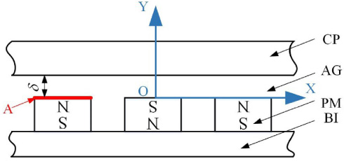
General model of the LPMECB.
After the Kirchhoff’s second law is used to simplify Fig. 2, the equivalent magnetic circuit of the LPMECB is obtained (Fig. 3).
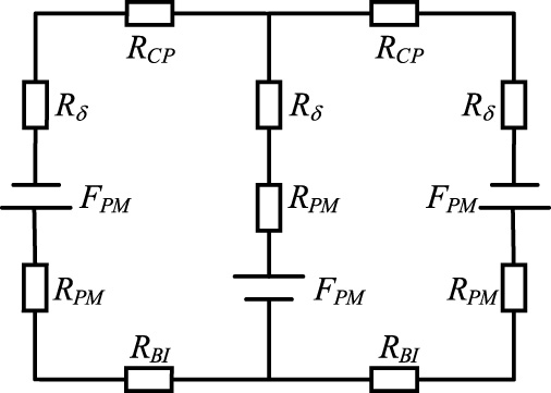
Equivalent magnetic circuit.
As shown in Fig 2, F
PM
is the magnetic potential of the PM, R
PM
is the PM reluctance, R
δ is the AG reluctance, R
CP
is the CP reluctance, R
BI
is the BI reluctance. The calculation formulas of F
PM
and R are as follows:
Finally, the magnetic flux of the thin-walled cylinder is obtained by calculus.
According to Faraday Effect, the induction electromotive force of the thin-walled cylinder is obtained.
The resistance of the thin-walled cylinder is as follows:
According to Eq. (9) and Eq.(10), the instantaneous value of eddy current of the thin-walled cylinder is as follows:
The total instantaneous value of eddy current is obtained by the integration of Eq. (11):
The effective value of eddy current is as follows:
The expression of B
δ is obtained by Eq. (7). The power density of the thin-walled cylinder is as follows:
The total power of the cylinder is obtained by the integration of Eq. (14):
Based on the effective power formula of resistance loads
According to P = F ⋅ v, the analytical solution of the braking force F can be obtained as follows:
The vacuum permeability is a very small value. In the above modeling process, according to Eq. (6), the AG reluctance (R δ) is the largest in the magnetic path of Fig. 3. With Eq. (7), the AG reluctance (R δ) will affect the value of the magnetic flux density of the AG (B δ). The bigger the AG reluctance (R δ) is, the smaller the magnetic flux density (B δ) is. According to Eq. (8), the smaller the magnetic flux density (B δ) is, the smaller the magnetic flux of the thin-walled cylinder (Φ) is, and further the smaller the induction electromotive force of the thin-walled cylinder (ϵ) in Eq. (9) is. According to Eq. (14), the power density of the thin-walled cylinder (dp) is proportional to the square of the induction electromotive force (ϵ) and inversely proportional to the resistance of the thin-walled cylinder (Dr). Therefore, when the induction electromotive force (ϵ) decreases and the resistance of the thin-walled cylinder (Dr) remains unchanged, the power density (dp) will be greatly reduced. And the effective power of the cylinder (P e ) is obtained by integrating the power density (dp). Finally, in Eq. (17), the braking force (F) is proportional to the effective power of the cylinder (P e ). In other words, the braking force (F) will also have a sharp decrease with the effective power (P e ). From the above analysis process, the AG reluctance (R δ) has a great influence on the braking force (F). Therefore, reducing the AG reluctance (R δ) is an effective way to improve the braking force (F), especially for the hoisting equipment with great AG length.
When there is a great AG length between the hoisting equipment and the PM, a novel structure of the LPMECB, named the H-type LPMECB, is proposed in order to compensate the influence of the AG. The H-type LPMECB adds IFs in the AG, as shown in Fig. 4. These IFs are rectangular sheets made of pure iron. L is the width of the PM, l is the distance between two adjacent IFs, and δ is the AG length.

3-D FEM: (a) LPMECB, (b) H-type LPMECB.
The braking force can be calculated by analytical model [21] and FEM [7]. Finite element modelling is relatively a time saving method compared with the analytical modelling approach. As the H-type LPMECB is unprecedented, there is no reliable analytical model to calculate the braking force of the H-type LPMECB. Therefore, 3-D FEM is selected to simulate the braking force in this paper. This paper has proved the correctness of the FEM of the LPMECB in previous work [1]. IFs with thickness of 0.1 mm are added on the basis of the LPMECB.
In this model, the PMs are distributed uniformly along the length direction of the CP, pure iron is selected for the BI. Considering the processing error and installation error in the test system, gaps between the IFs and the CP in this model is set to 2 mm. The key parameters of Fig. 4 are shown in Table 1. The mesh of the CP, the IF, the PM and BI is set as extra fine, and the mesh of air is set as normal. The stationary solution is automatically used as the initial condition. The boundary conditions are automatically created between various components of the LPMECB when forming an assembly. Use Magnetic Flux Conservation in the non-conducting domains and Ampère’s Law in the conducting domains. Set the PM as a user defined domain with remanence and permeability.
Parameters of the H-type LPMECB
Geometry optimization
Based on the FEM in Section 3, the change curves of the braking force (F) of the H-type LPMECB vs the distance between two adjacent IFs (l) are obtained in Fig. 5 under different speeds.

Simulations: F of the H-type structure vs l∕L.
As Fig. 5 shows, the relationship between the braking force (F) and the distance between two adjacent IF (l) of the H-type structure is nonlinear. There is a peak value in each curve, which means the distance between two adjacent IF (l) can be optimized to achieve maximum braking force of the H-type structure. The reason why the simulation curve displays such a characteristic is that the distance between two adjacent IF (l) affects the AG reluctance in the magnetic circuit, and then affects the size of the braking force (F). The peak values of the four curves are corresponding to l = 0.25 ∗ L, which is independent of speed (v).
According to the results in Fig. 5, the optimal distance between two adjacent IFs of the H-type LPMECB (l) is 0.25 ∗ L. When l is set to 0.25 ∗ L, the braking force (F) comparison between the H-type LPMECB and the LPMECB at different speeds (v) are shown in Fig. 6.
Figure 6 shows that the two curves are monotonously increasing. The braking force (F) of the H-type LPMECB is obviously greater than that of the LPMECB. The reason for this phenomenon is that the braking force (F) of the LPMECB and the H-type LPMECB is proportional to the speed (v), which is in line with the basic principle of the eddy current brake.

Simulations: F of the H-type LPMECB and the LPMECB under different v.
In order to measure the braking performance of the H-type LPMECB, the following proportion parameter is defined:

Simulations: k of the H-type LPMECB under different v.
As shown in Fig. 7, the proportion parameter (k) of the H-type LPMECB is between 251%–257%, which proved that the H-type LPMECB have a great impact on the improvement of braking force of the LPMECB, and the proportion parameter (k) of the H-type LPMECB is slightly affected by speed (v) at lower speeds.
The contrast curves between the braking force (F) of the H-type LPMECB and that of the LPMECB are obtained at different AG lengths (δ), as shown in Fig. 8, when v = 2 m/s, and the distance between two adjacent IFs (l) of the H-type LPMECB is set to 0.25 ∗ L. The gaps between the IFs and the CP are 2 mm and remain unchanged.

Simulations: F of the H-type LPMECB and the LPMECB under different δ.
The two curves in Fig. 8 monotonously decrease, and the braking performance of the H-type LPMECB is better than that of the LPMECB under different AG lengths (δ). The reason for this characteristic is that the H-type LPMECB reduces the AG reluctance.
In order to research the change rate (b) of the braking force of the H-type LPMECB and compared with that of the LPMECB at different AG lengths (δ), the following parameter is defined:

Simulations: b of the H-type LPMECB and the LPMECB under different δ.
As Fig. 9 shows, the two curves basically coincide. The braking force (F) of the H-type LPMECB and that of the LPMECB are both reduced by about 60%, which indicates that the influence of AG length (δ) on braking force (F) of the H-type LPMECB and the LPMECB is basically similar. Although the H-type LPMECB reduces the AG reluctance, it can not completely eliminate the influence of the AG reluctance on the braking force (F) of the H-type LPMECB and the LPMECB.

(a) A test system of the LPMECB, (b) the structure of the trolley without IFs, (c) the structure of the trolley with IFs.
The analytical model in Section 3 demonstrates that the braking force is caused by the relative motion between CP and PMs, regardless of whether the CP are moving parts or not. In this context, a test system of the LPMECB is built to validate the simulations. The test system consists of the CPs, PMs, IFs, IF retainers, BI, a DC power supply, a data acquisition system, sensors and a trolley. The PMs, IFs, IF retainers, BI, DC power supply, and data acquisition system and sensors are fixed on the trolley, which can slide freely on the slide rail. The test system is shown in Fig. 10(a), the original structure trolley and the trolley fitted with the IFs are shown in Figs 10(b) and 10(c) respectively. The H-type LPMECB with different distance between two adjacent IFs (l) can be obtained by changing the different retainers. The connection between PMs, IFs and IF retainers is glued, which can avoid the deformation of the IFs during the movement of the trolley. The IF retainers are printed with PLA material by 3D printing technology. The initial parameters in the experiment are consistent with the simulation model.
The experimental process is as follows. Initially, the trolley enters the CP area at a certain speed. Next, the position of the trolley is determined by the position of the sensor signal, and the speed of the trolley is detected in real time by the speed sensor. Finally, the data acquisition system is used to collect and transmit sensor signals to a host computer. The acceleration and resultant force of the trolley can be calculated by MATLAB according to the speed, the position and the weight of the trolley. After the resultant force subtracts the dynamic friction of the trolley, the braking force (F) is obtained. The dynamic friction of the trolley is about 10.18 N. The braking performance of the H-type LPMECB is measured and compared with that of the LPMECB to validate the simulations.
It only takes 0.4 seconds to reduce the speed of the trolley from 2.8 m/s to 0.4 m/s. During the deceleration process, the heat generated inside the CP is small, and the temperature rise of the CP can be neglected. Therefore, the influence of temperature can be ignored in this paper. In the test system, the change curves of the braking force (F) of the H-type LPMECB with the distance between two adjacent IFs (l) of the H-type structure are acquired for different speeds (v), namely, 1.6 m/s, 2 m/s, 2.4 m/s and 2.8 m/s, as shown in Fig. 11.

Experiments: F of the H-type LPMECB vs l.
As Fig. 11 shows, the relationship between the braking force (F) of the H-type structure and the distance between two adjacent IF of the H-type structure (l) is nonlinear. There is a maximum value in each curve, and the peak values of the four curves are corresponding to l = 0.25 ∗ L, which is independent of speed (v).

Experiments: F of the H-type LPMECB and the LPMECB under different v.
According to the optimization results in Fig. 11, the distance between two adjacent IF of the H-type structure (l) is set to 0.25 ∗ L. The comparison between the braking force (F) of the H-type LPMECB and the LPMECB at different speeds (v) is shown in Fig. 12.
Figure 12 shows that the two curves are monotonously increasing, and the braking force (F) of the H-type LPMECB is obviously larger than that of the LPMECB. After calculating the data in Fig. 12 by using the Eq. (18), the curve of the proportion parameter (k) vs speed (v) are obtained, as shown in Fig. 13. In order to compare the experimental results with the simulation results, the curve shown in Fig. 7 is added to Fig. 13.

Experiments: k of the H-type LPMECB under different v.
As shown in Fig. 13, the proportion parameter (k) of the H-type LPMECB is between 290%–360%. These data proved that the H-type LPMECB have a great impact on the improvement of braking force of the LPMECB. In the experimental results, the braking force of the H-type LPMECB is about 2.85–3.55 times that of the LPMECB. In the simulation results, the braking force of the H-type LPMECB is about 2.50–2.60 times that of the LPMECB. The experimental and simulation results show that the braking force of the H-type LPMECB is about three times that of the LPMECB. Compared with the simulation results, the experimental results have differences in amplitude, but the optimization degree of experimental results is basically consistent with that of the simulation results. The reason of this phenomenon is considered to be irregular vibration of the trolley during operation.
The contrast curves between the braking force (F) of the H-type LPMECB and that of the LPMECB at different AG lengths (δ), as shown in Fig. 14, when v = 2 m/s, and the distance between two adjacent IFs (l) of the H-type LPMECB is set to 0.25 ∗ L.

Experiments: F of the H-type LPMECB and the LPMECB under different δ.
The two curves in Fig. 14 are monotonously decreasing, and the performance of the H-type LPMECB is better than that of the LPMECB under different AG lengths (δ).
After data processing of Fig. 14 by using the Eq. (19), the proportion parameter (k) of the H-type LPMECB is obtained and compared with that of the LPMECB, as shown in Fig. 15.

Experiments: b of the H-type LPMECB and the LPMECB under different δ.
As Fig. 15 shows, the b values of the H-type LPMECB and the LPMECB increase as δ increases from 7 mm to 17 mm. The increase range of the two curves is similar, which is basically consistent with the simulations.
In this paper, the analytical model was established by using the equivalent magnetic circuit method, and the AG reluctance is greater than that of the other parts of the LPMECB with a large AG length. Based on this, the H-type LPMECB is proposed in order to compensate the influence of AG. The geometry parameter of the IFs is then optimized, and the optimal geometry parameter of the IFs of the H-type LPMECB is 0.25 ∗ L. In addition, this paper measured the braking performance of the H-type LPMECB through FEM, compared with the LPMECB. The braking force of the H-type LPMECB is about three times that of the LPMECB. Finally, the experiments validated the simulations with a developed test system. In general, good agreements between the simulations and the experiments are achieved.
This work is significant, as it proposes the H-type LPMECB, optimizes the geometry parameter of the IFs of the H-type LPMECB, and measures the braking performance of the H-type LPMECB. Future work will research the effect of the IFs deformation caused by collision between the IFs and the CP on the braking force of the H-type LPMECB at a higher speed and a larger AG length.
Footnotes
Acknowledgements
This work was supported in part by the Jiangsu Provincial Natural Science Foundation of China (BK20180033), in part by the National Natural Science Foundation of China (61971423), and in part by the Priority Academic Program Development of Jiangsu Higher Education Institutions (PAPD).