
Abstract
To improve the speed and position detection accuracy of surface-mount permanent magnet synchronous motor (SPMSM) vector control and reduce unnecessary chattering of the system, this paper proposes a sensorless control strategy of SPMSM based on an adaptive sliding mode observer (ASMO) with optimized phase-locked loop (OPLL) structure. First, in order to overcome the chattering of system caused by discontinuous switching characteristic of signum function in conventional sliding mode observer (CSMO), a continuous saturation function is selected as the switching function. The ASMO adopts the system state-related adaptive gain function to adjust the switching gain value of the system in real time, which overcomes the slow response speed or severe chattering of the system caused by the constant switching gain of CSMO. Second, to reduce the phase delay between the rotor position estimation value and the actual value caused by the adoption of low-pass filter (LPF) and the position estimation error caused by arctangent function method, an OPLL method is designed for accurate estimation of rotor position and speed. Finally, the effectiveness and feasibility of the proposed improved SMO algorithm is verified by simulation and experiments on an SPMSM with rated power of 2 kW.
Keywords
Introduction
Permanent magnet synchronous motor (PMSM) has the advantages of high-power density, small inertia, simple structure and wide speed regulation range, and is widely used in industrial fields [1–3]. In practical engineering applications, the vector control strategy of PMSM needs to obtain accurate rotor position and speed information, which are usually measured by mechanical position sensors installed on the motor shaft, such as shaft encoder and resolver. However, the additional information detection equipment not only increases the design cost, but also increases the size and inertia of PMSM, and it reduces the performance and reliability in harsh environment [4–6]. Therefore, sensorless control of PMSM has become a popular topic.
The sensorless control method of PMSM can estimate rotor position and speed in real time from the phase current and phase voltage signal of the motor, so no additional position sensor device is required. At present, most sensorless control methods for PMSM can be classified into two categories: one is the high-frequency signal injection method based on salient pole effect of motor [7–10], the other is the back electromotive force (back-EMF) methods based on basic model of motors [11–13]. High-frequency signal injection method is suitable for motors in low-speed or static state, but the injected signal often causes q-axis current oscillation and large torque ripple, which is easy to generate noise [14]. The second method is often adopted for the SPMSM in the middle-high speed operations, that is, the back-EMF-based or the flux-based mathematical model is used to design the corresponding observer estimating the rotor position and speed of the motor. Common methods based on back-EMF model mainly include model reference adaptive system (MRAS), extended Kalman filter (EKF) and sliding mode observer (SMO). However, MRAS method has the advantages of simple algorithm structure and easy implementation, but the method has high requirements for parameter accuracy and cannot guarantee the stability of the control system all the time [15]. EKF method only retains the first-order term in the Taylor series expansion of the nonlinear state equation, which leads to the truncation error of the higher-order term. Meanwhile, the filtering process of EKF is greatly affected by the given noise covariance matrix. If the noise covariance matrix is not selected properly, it will seriously affect the convergence of the filtering process [16,17].
Compared with other observers, SMO has been widely used in sensorless control of PMSM because of its advantages, including simple structure, strong robustness to disturbances and parameter variations, and good dynamic performance [18]. However, the rotor position and speed estimation of CSMO is realized based on the motor back-EMF model, and due to the gap between the permanent magnets will lead to the interference of high-order harmonics in the estimated back-EMF signal, which will seriously affect the estimation performance of the sensorless control system of PMSM, resulting in chattering. Therefore, it is necessary to introduce LPF and phase compensation module into the control system, but it increases the computational complexity of the algorithm [19]. To solve this problem, in [20], an SMO based on delay suppression is proposed, which fully considering the delay problem caused by LPF and digital calculation. The current pre-compensation method based on double current sampling technology is adopted to compensate the calculation delay in one switching cycle, which improves the accuracy of position estimation. In [21], a feed-forward phase-locked loop to suppress the steady-state position tracking error during variable speed operation, and then used the dynamic error coefficient method to improve the position estimation performance of the feed-forward phase-locked loop. In [22,23], a fuzzy flux SMO based on PLL is proposed, and the fuzzy control idea is used to realize the adaptive adjustment of the switching gain of the SMO, so as to improve the position and speed estimation accuracy of sensorless control of PMSM and reduce the high-frequency chattering of the system. In [24], a sensorless control of PMSM based on iterative flux SMO is proposed, which adopts iterative idea. To reduce the chattering in the estimation results, the improved SMO is iteratively used to adaptively adjust the sliding mode switching gain in one current sampling period. In [25], a shape coefficient self-adjusting adaptive fuzzy controller method based on hyperbolic tangent switching function, eliminates LPF and angle compensator, and reduces chattering caused by constant boundary layer thickness.
In this paper, an adaptive sliding mode observer (ASMO) with optimized phase-locked loop (OPLL) structure is proposed for sensorless control of SPMSM. The improved SMO adopts the continuous saturation function with variable boundary layer thickness instead of the conventional signum function as the switching function of SMO. At the same time, an adaptive sliding mode gain function related to the system state is designed, which can adaptively adjust the switching gain of the observer according to the system state, and overcome the problem of slow response or serious chattering of the system caused by constant gain of CSMO. In addition, in order to overcome the phase delay of the system caused by the addition of LPF and the low estimation accuracy of the system caused by the arctangent function method, this paper adopts OPLL method instead of conventional estimation method to accurately estimate rotor position and speed, and further improves the accuracy of system estimation by increasing the degree that the sine factor tends to zero in the normalization process of back-EMF. The effectiveness and feasibility of the proposed improved SMO are verified by comparison with the simulation and experiment of CSMO.
The remainder of this paper is organized as follows. Section 2 describes the mathematical model of SPMSM, the design of CSMO based on switching function. Section 3 describes the design of improved SMO, the stability analysis of the control system, the estimation of rotor position and speed by optimizing phase-locked loop (OPLL) method. Section 4, the proposed method is analysed by simulation. Section 5. The results of the experimental verifications are presented. Finally, Section 6 draws the conclusions relating to the contributions of this paper.
Design of CSMO
This paper takes SPMSM as the research object, assuming that iron saturation, magnetic flux leakage, eddy current and hysteresis losses are negligible, the current state equation of the SPMSM in the 𝛼𝛽-axis stationary reference frame is as follows:
The back-EMF of each phase in the 𝛼𝛽-axis stationary reference frame can be expressed in the fixed frame as:
According to the variable structure, the sliding mode surface can be defined as follows:
According to the current state Eq. (1) of PMSM and the defined sliding surface (3), the CSMO can be expressed as:
The switching function sgn (s𝛼, 𝛽) is defined as follows:
By subtracting (1) from (4), the error equation of the stator current can be obtained as:
In order to maintain the system stable, the observer gain k should satisfy the following inequality conditions [18]:
When the system state reaches the sliding surface, the system tends to be stable, that is,
The extraction of rotor position information in CSMO is based on the arctangent function method, as follows:
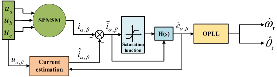
It should be noticed that when the system enters the sliding mode state, because of the discontinuous switching characteristics of the signum function itself, the system control variables will be interfered by the high frequency switching of the sliding mode switching function, resulting in chattering. Therefore, it is necessary to add an LPF module in the control system to filter out the high-order harmonic components in the estimated back-EMF signal, improve the estimation accuracy of the system and reduce chattering, as shown in Fig. 1. However, the introduction of LPF will lead to system estimation lag, and there is a certain phase delay between the estimated rotor position signal of SMO and the actual value. Then, to compensate the delay introduced by the LPF, an extra term Δθ is compensated to the calculated value to obtain the final position information. Compensation value Δθ is expressed as:
The estimated value of rotor position
Figure 1 shows the block diagram of the control structure using the CSMO method, in which u a , u b , u c are the three-phase power supply voltage of the motor stator.

Algorithm structure of the CSMO.
According to the analysis of the traditional synovial film observer in the previous section, although the traditional synovial film observer can track the rotor position information, due to the inherent discontinuous switching characteristics of the observer itself, the synovial film gain is a fixed value, which affects the buffeting fluctuation very large. Therefore, in order to reduce chattering, a smoother function can be selected to replace the traditional switching function, which can effectively reduce the impact of chattering on the system. The improved SMO is shown in Fig. 2.
Design of ASMO based on saturation function
The improved SMO is designed as:
The switching function sat (s𝛼, 𝛽) is defined as follows:
The expression of the proposed adaptive gain function H (s𝛼, 𝛽) is as follows:
When the current estimation error is large, that is, the system state is far away from the sliding surface, the limit position |s𝛼, 𝛽|→∞ is taken, and then |s𝛼, 𝛽|
h
→∞,
When the current estimation error gradually decreases, that is, the system state gradually approaches the sliding mode surface, the limit position |s𝛼, 𝛽|→0 is taken, and then |s𝛼, 𝛽|
h
→0,
According to (14), when the system is far away from the sliding surface, the switching gain value increases, which can ensure that the system can quickly approach the sliding surface; when the system is close to the sliding surface, the switching gain value decreases, which ensures that the system can have small fluctuations near the sliding surface. Therefore, compared with CSMO, it not only improves the response speed of the system, but also reduces the chattering of the system and improves the stability of the system.
By subtracting (1) from (12), the error equation of the stator current can be obtained as:
When the system state reaches the sliding surface, the system tends to be stable, that is, according to the equivalence principle of sliding mode control, the control variables at this time can be regarded as equivalent control variables, which can be expressed as:
To ensure the stability of the designed observer, the Lyapunov function is constructed as follows:
It can be obtained from (17)
Substitute (1) and (15) into (18), it can be further derived as
In order to ensure that the system converges to the sliding surface in finite time, according to Lyapunov stability theory, the stability conditions of the control system are:
To satisfy the requirements of system stability, the following formula should be satisfied:
It can be inferred from the above that when the system state is far from the sliding mode surface, the sliding mode gain function H (s𝛼, 𝛽) satisfies H (s𝛼, 𝛽) > k, and k is the fixed switching gain determined by CSMO. Therefore, when the system current estimation error is large, H (s𝛼, 𝛽) always satisfies (22). When the system state gradually approaches the sliding mode surface, the sliding mode gain function H (s𝛼, 𝛽) satisfies
Algorithm structure of the ASMO.
CSMO extracts rotor position and speed information from estimated back-EMF signal by arctangent function method. Because of the existence of system noise and the nonlinearity of inverter, high-order harmonic components will be generated in the estimated back-EMF signal, which will have a certain impact on the system estimation performance. Although LPF can effectively filter out high-order harmonics in the back-EMF signal, it will inevitably cause the phase lag between the estimated rotor position and the actual rotor position. The introduction of phase compensation module actually increases the computational complexity of the system. Therefore, when the arctangent function method is used to estimate the rotor position and speed, the estimation accuracy of the system is often low.
In order to improve the estimation accuracy of the system, this paper adopt phase-locked loop (PLL) method to estimate the rotor position and speed. As a closed-loop phase negative feedback system, the PLL method can not only filter waves the input back-EMF signal, but also control the frequency and phase of the internal oscillation signal by using the input signal, so as to realize the automatic tracking of the output signal frequency and phase to the input signal frequency and phase. The structure block diagram of the conventional PLL is shown in Fig. 3, which is mainly composed of phase discriminator (PD), loop filter (LF) and voltage-controlled oscillator (VCO) [22].
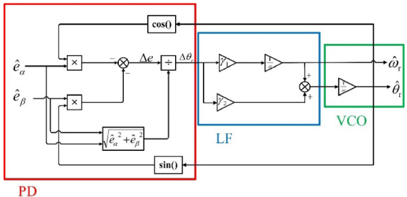
The structure lock diagram of the conventional PLL.
The rotor position estimation error can be obtained by normalizing processing the back-EMF signal:
When the system tends to be stable, the rotor position error satisfies
However, when the conventional PLL normalizes processing the input back-EMF signal, the sine factor

The structure block diagram of the OPLL.
It can be obtained from Fig. 4:
Substituting (2) and (11) into (25) to obtain:
When SPMSM approaches steady state,
Therefore, R
e
𝛼
and R
e
𝛽
is further obtained as:
By subtracting (29) from (28), the error Δe can be obtained as
At this time, because
Therefore, the estimated rotor position and speed information can be expressed as:
To verify the effectiveness of the improved SMO, a simulation model of SPMSM sensorless control system is established by MATLAB/Simulink, and the ASMO based on OPLL structure was simulated and analysed. The structure block diagram of SPMSM vector control system based on improved SMO is shown in Fig. 5. The SPMSM with rated power of 2 kW is used as the driving prototype, and the parameters of SPMSM in simulation are shown in Table 1.

Structure block diagram of SPMSM vector control system based on improved SMO.
Parameters of the SPMSM prototype
Figure 6 shows the steady-state simulation results of speed tracking response and estimation error of SPMSM control system with CSMO and improved SMO when the speed reaches 1000 r/min under no-load condition. Figures 6(a) and 6(b) show the speed tracking and speed estimation error curves of the system with CSMO, respectively. It can be seen that when the motor reaches the steady-state speed, the system appears obvious chattering and large speed fluctuation, and the estimated speed cannot track the actual speed well. The maximum estimation error amplitude of speed is 11.92 r/min, accompanied by signal overshoot. Figures 6(c) and 6(d) show the speed tracking and speed estimation error curves of the system with improved SMO, respectively. It can be seen that when the motor reaches the steady-state speed, the estimated speed tracking ability is significantly improved and the chattering of the system is effectively suppressed, and the maximum estimation error amplitude of speed is only 2.22 r/min. Therefore, compared with the CSMO, the improved SMO has better speed tracking performance.

Simulation results of SPMSM speed based on CSMO and improved SMO at 1000 r/min. (a) speed estimation of CSMO, (b) speed estimation error of CSMO, (c) speed estimation of improve SMO, (d) speed estimation error of improve SMO.
Figure 7 shows the steady-state simulation results of rotor position and position estimation error of SPMSM control system with CSMO and improved SMO when the speed reaches 1000 r/min under no-load condition. Figures 7(a) and 7(b) show the rotor position and position estimation error curves of the system with CSMO, respectively. It can be seen that the rotor position estimation error is large in the motor acceleration stage, and the maximum estimation error amplitude is 0.41 rad. At the same time, the estimated rotor position cannot track the actual rotor position well, and there is a certain phase lag between the actual rotor position and the estimated rotor position. Figures 7(c) and 7(d) show the rotor position and position estimation error curves of the system with improved SMO, respectively. It can be seen that since OPLL has the same filtering characteristics as LPF, the estimated rotor position does not fluctuate greatly, and the position estimation error is relatively small even in the motor acceleration stage. When the system reaches the steady state, the maximum estimation error amplitude is only 0.16 rad, and the phase lag problem has been significantly improved. Therefore, compared with the CSMO, the improved SMO has better position estimation accuracy.

Simulation results of SPMSM rotor position estimation based on CSMO and improved SMO at 1000 r/min. (a) position estimation of CSMO, (b) position estimation error of CSMO, (c) position estimation of improve SMO, (d) position estimation error of improve SMO.
Figure 8 shows the simulation results of estimation back-EMF signal of SPMSM control system in the 𝛼𝛽-axis with CSMO and improved SMO when the speed reaches 1500 r/min under no-load condition. Figures 8(a) and 8(b) show the estimated back-EMF signal curves of CSMO and improved SMO, respectively. It can be seen that when the CSMO is used for back-EMF observation, although the introduction of LPF plays a certain filtering role, the influence of high-order harmonic interference and noise still exists, resulting in chattering and burrs phenomenon in the estimated back-EMF signal in Fig. 8(a). Due to the correct selection of the switching function, the adaptive on-line adjustment of the switching gain and the unique filtering ability of OPLL, the proposed improved SMO can effectively eliminate the noise and harmonic components in the estimated back-EMF signal, and the estimated signal curve in Fig. 8(b) tends to be smoother.

Estimated 𝛼𝛽-axis back-EMF waveform at 1000 r/min with no load. (a) the CSMO, (b) the improved SMO.
Figure 9 shows the simulation results of 𝛼-axis current error and sliding mode gain function in SPMSM control system with improved SMO when the speed is set at 1000 r/min. Figure 9(a) shows the 𝛼-axis current error curve, and Fig. 9(b) shows the sliding mode gain function response curve. It can be seen that with the gradual reduction of current error, the corresponding sliding mode gain value is also gradually decreasing. When the current error is 0, the sliding mode gain can be guaranteed to take the minimum value of 126, which is 1.59 times lower than the conventional constant gain coefficient. When the current error is the largest, the sliding mode gain can be guaranteed to take the maximum value of 248, which is 1.24 times higher than the conventional constant gain coefficient. Therefore, the adaptive sliding mode gain function designed in this paper can be adjusted adaptively with the change of system state, and the response speed of parameter adjustment is fast.

Simulation results of 𝛼-axis current error and sliding mode gain function value of SPMSM control system based on improved SMO at 1000 r/min. (a) 𝛼-axis current error, (b) sliding mode gain function value.
Figure 10 shows the dynamic simulation results of speed step response of SPMSM control system with CSMO and improved SMO under the rated load. SPMSM accelerates from 0 to 1000 r/min and then to 1500 r/min after 0.1 s. Figures 10(a) and 10(b) show the speed step response curves of CSMO and improved SMO, respectively. It can be seen that, similar to the steady-state simulation results of Fig. 6, Fig. 10(a) shows that there are obvious speed estimation fluctuations and system chattering when the motor accelerates or operates stably, and even in the high-speed steady-state stage, chattering is still obvious. Figure 10(b) shows that the improved SMO can ensure that SPMSM has good speed tracking performance in both acceleration and steady-state stages, and the high-frequency chattering problem of the system has been effectively improved regardless of medium speed or high speed of the motor. Therefore, compared with the CSMO, the SPMSM control system based on the improved SMO has good adaptability and robustness.

Simulation results of speed step response of SPMSM control system under the rated load, (a) the CSMO. (b) the improved SMO.
Figure 11 shows the dynamic simulation results of the SPMSM control system with CSMO and improved SMO under the sudden load when the speed is 1000 r/min at rated torque. After the SPMSM is set to operate stably for 0.1 s, the torque of the system increases by 3 N⋅m instantly. Figures 11(a) and 11(b) show the speed estimation curves of CSMO and improved SMO under the sudden load, respectively. It can be seen that the speed of control system with CSMO fluctuates greatly after being affected by the instantaneous load, and the maximum speed fluctuation amplitude is 31.8 r/min. Due to the robustness of SMO itself, the system recovers to the reference speed after 0.015 s. However, the speed of control system with improved SMO also showed instantaneous fluctuation after the addition of the sudden load, but compared with Fig. 11(a), the speed overshoot is smaller, and the maximum speed fluctuation amplitude is 13.9 r/min, and the system quickly recovers to the reference speed after 0.006 s. Therefore, compared with the CSMO, the improved SMO has good anti-interference performance and fast dynamic response characteristics.

Speed response at 1000 r/min with the sudden load of 3 N⋅m. (a) the CSMO, (b) the improved SMO.
Figure 12 shows the simulation results of speed estimation error of SPMSM control system with improved SMO when the speed is set at 1500 r/min and the interval coefficient c value is −1, 0.1, 0.5, 1, 5 and 10. It can be seen that when c is −1, the estimated error signal has obvious overshoot, the maximum speed estimation error amplitude is 4.95 r/min. When c is 0.1 and 0.5, the speed error signal fluctuation is still obvious, and the maximum estimated speed error amplitude of the system is 7 r/min and 2.83 r/min, respectively. Only when c is 1, 5 and 10, the fluctuation of speed estimation error is obviously restrained. When c is 1, the system estimation accuracy is the highest. With the continuous increase of c value, the speed estimation error basically does not change.
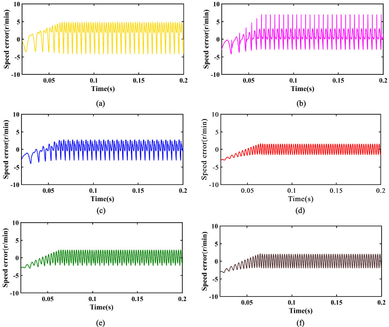
Simulation results of speed estimation error of SPMSM control system based on adaptive SMO under different c values at 1500 r/min. (a) c = −1, (b) c = 0.1, (c) c = 0.5, (d) c = 1, (e) c = 5, (f) c = 10.
The sensorless control experiment of SPMSM based on improved SMO proposed in this paper is carried out on a motor with a rated power of 2 kW and the rated parameters of the motor are consistent with Table 1, and the experimental platform is shown in Fig. 13. It can be seen that the experimental platform mainly includes DSP digital signal processor, SPMSM prototype, magnetic particle brake, DC power supply, industrial inverter, Hall current sensor, data acquisition card and speed-torque sensor, etc. The experimental motor, speed-torque sensor and magnetic particle brake are connected through the coupling. The load required in this experiment outputs different current values through torque control current source to adjust the magnetic particle brake output the corresponding load torque. The experimental conditions are consistent with the simulation, where the PWM switching frequency is set to 10 kHz and the sampling period is set to 0.0001 s.

Experimental hardware platform.
Figure 14 shows the experimental results of speed tracking and speed estimation error of SPMSM control system with CSMO and improved SMO. Figures 14(a) and 14(b) show the speed tracking and speed estimation error curves of the control system with CSMO, respectively. It can be seen that when the CSMO method is used for speed estimation, the system will appear obvious chattering, where the maximum speed estimation error is 24.1 r/min and the steady speed estimation error is 14.2 r/min. Figures 14(c) and 14(d) show the speed tracking and speed estimation error curves of the control system with improved SMO, respectively. It can be seen that the system chattering problem is effectively improved under the improved SMO method, where the maximum speed estimation error is 10.4 r/min and the steady speed estimation error is 6.8 r/min. The experimental results are similar to the simulation results, which shows that the improved SMO method proposed in this paper has good speed tracking performance and chattering suppression performance.

Experimental results of SPMSM speed based on CSMO and improved SMO at 1000 r/min. (a) speed of CSMO, (b) speed estimation error of CSMO, (c) speed of improved SMO, (d) speed estimation error of improved SMO.
Figure 15 shows the experimental results of rotor position and position estimation error of SPMSM control system with CSMO and improved SMO. Figures 15(a) and 15(b) show the rotor position and position estimation error curves of the control system with CSMO, respectively. It can be seen that there is a certain phase lag between the rotor position estimated by CSMO and the actual value, and the error fluctuates greatly, the maximum steady-state estimation error is 0.7 rad. Figures 15(c) and 15(d) show the rotor position and position estimation error curves of the control system with the improved SMO, respectively. It can be seen that the estimated rotor position of SMO can well track the actual rotor position. Due to the existence of the calculation delay of the control processor, there is a relatively small phase lag between the estimated value and the actual value of the motor rotor position, and the maximum steady-state estimation error of the rotor position is only 0.36 rad. The experimental results show that the improved SMO proposed in this paper has higher system estimation accuracy, and the problem of system phase lag has been effectively improved.
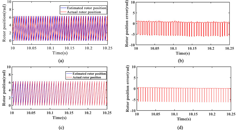
Experimental results of SPMSM rotor position estimation based on CSMO and improved SMO at 1000 r/min. (a) position estimation of CSMO, (b) position estimation error of CSMO, (c) position estimation of improved SMO, (d) position estimation error of improved SMO.
Figure 16 shows the experimental results of speed step response of SPMSM control system with CSMO and the improved SMO. It can be seen from Fig. 16 that in the steady-state stage of 1000 r/min and 1500 r/min, the estimated speed of the CSMO appears obvious chattering, and even a slight lost step phenomenon occurs in the acceleration stage. In addition, it takes 0.56 s of acceleration time for SPMSM to converge to the steady state, and the maximum speed estimation error is 24.5 r/min at the initial stage of reaching 1500 r/min. It can be seen from Fig. 16, using the improved SMO, that during the acceleration of SPMSM, the estimation error is reduced to less than 15 r/min, and with the continuous increase of the rotating speed, the motor does not appear obvious unstable state, and the acceleration stage is stable. At the same time, the motor speed converges to the steady-state stage of 1500 r/min, and the acceleration time is 0.51 s. The experimental results show that the improved SMO has good chattering suppression performance and fast dynamic response characteristics.

Experimental results of speed step of SPMSM control system based on CSMO and improved SMO.
Figure 17 shows the experimental results of the SPMSM control system with CSMO and the improved SMO, under the sudden load when the speed is 1000 r/min at rated torque. After the SPMSM is set to operate stably for 10 s, the torque of the system increases by 3 N m instantly. Figures 17(a) and 17(b) show the speed estimation curves of CSMO and improved SMO under system load mutation, respectively. It can be seen from Fig. 17(a) that the estimated speed of SPMSM control system with CSMO fluctuates instantaneously under abrupt change of load, and the maximum amplitude of speed fluctuation is 47.05 r/min. Due to the inherent robustness of SMO, the system returns to steady-state after 0.86 s. In addition, the estimated speed buffeting degree increases significantly compared with that before no-load, and the maximum speed fluctuation amplitude increases to 37.5 r/min. It can be seen from Fig. 17(b) that the estimated speed of the control system with the improved SMO also fluctuates instantaneously under abrupt change of load, but the maximum estimated speed fluctuation amplitude is only 29.2 r/min, and the system recovery time is shortened to 0.58 s. Therefore, the proposed improved SMO not only has good chattering suppression performance, but also realizes fast convergence under load mutation, and has better robust performance.

Experimental results of load mutation of SPMSM control system based on CSMO and improved SMO. (a) speed estimation of CSMO, (b) speed estimation of improve SMO.
In this paper, a sensorless control strategy of SPMSM based on an adaptive sliding mode observer (ASMO) with optimized phase-locked loop (OPLL) structure is proposed. The improved SMO adopts the continuous saturation function with variable boundary layer thickness as the sliding mode switching function, and designs the adaptive sliding mode gain function related to the system state, which can realize the on-line adjustment of the switching gain and effectively suppress the system chattering. At the same time, in order to overcome the system phase lag caused by adding low-pass filter (LPF) and the system estimation error caused by arctangent function method, an optimized phase-locked loop method is designed for rotor position and speed estimation. The OPLL method can further improve the estimation accuracy of the system by increasing the degree of sine factor tending to zero in the normalization of back-EMF. The stability of the control system under the improved SMO is proved by Lyapunov stability theorem, and the effectiveness and feasibility of the improved control algorithm are verified by simulation and experiment. The simulation and experimental results show that compared with the CSMO, the improved SMO has better speed tracking ability, system estimation accuracy and fast dynamic response characteristics, and the high-frequency buffeting problem of the system is effectively suppressed.
Footnotes
Conflict of interest
The authors declare no conflict of interest, financial or otherwise.