
Abstract
As one sort of flux modulation machine based on magnetic gear effect, field-modulated machine features with low speed large torque. A novel hybrid excitation field-modulated machine (HEFMM) is proposed by introducing the concept of hybrid excitation, the flux modulation poles (FMPs) and excitation winding of which are emplaced in stator teeth and the adjacent FMPs. It can be maintained wide speed range operation through the processes of flux-enhancing and flux-weakening with no increasing machine bulk, as well as the numbers of stator and rotor slot. The working principle of proposed machine is deeply studied, as well as basic electromagnetic characteristics are calculated by finite element method, including no-load magnetic flux linkage, no-load back electromotive force, cogging torque and output torque. In addition, the processes of flux-enhancing and flux-weakening are analyzed. Finally, one prototype with one kilowatt was built and its static characteristics were tested. The results show that the proposed HEFMM has the features of high torque density, small cogging torque and wide speed range, which is promising candidate for electric vehicle direct drive field.
Introduction
Due to the improvement of high-performance permanent magnet (PM) material manufacturing technology, permanent magnet synchronous machine (PMSM) obtains obvious advantages in power density and efficiency, and its application fields have been widened rapidly in past decades [1,2]. For low-speed direct drive industrial applications, such as electric vehicles, direct drive PMSM features gearless transmission, which can avoid a series of problems caused by mechanical gear transmission. Consequently, low speed direct drive PMSM is one promising candidate for the applications of direct drive industry, which has become a research hotspot because its efficiency, service life and reliability has obtained improved [3,4]. However, in order to achieve low speed and high torque, the number of pole slots of traditional direct drive PMSM is generally large, which leads to large machine volume and brings great difficulties to manufacturing, assembly and transportation [5–7].
With the introduction and application of non-contact magnetic gear, high torque density magnetic field modulation machine based on ‘magnetic gear effect’ has come into one feasible solution in recent years. By combining concentric magnetic field modulated magnetic gear with traditional PMSM, magnetic gear composite permanent magnet machines are proposed in [8], respectively. This kind of machine combines the advantages of outer rotor PMSM and novel magnetic gear, and greatly improves the output torque under the same parameters. However, the theoretical magnetic field analysis and manufacturing of this sort of compound machine are relatively complex due to a three-layer air gap structure, which limits its industrial application. Based on prior studies above mentioned, various types of novel magnetic field modulation machines (MFMMs) have been designed and developed in [9–14]. Compared with the magnetic gear composite machines, MFMMs have simple structure and convenient processing. Compared with the magnetic gear composite motor, this type of motor has simple structure and convenient manufacturing. The single-layer air gap structure enables it to fully use the analysis, design and computering methods of conventional PMSM. The working principle of a MFMM is based on the principle of magnetic gear, and minimal positional changes on the rotor can cause significant changes in the magnetic field in the stator space. The number of poles in PMs is not equal to the number of poles in the armature winding. The uniformly arranged modulation poles result in a single pole number in the magnetic flux. When the magnetic potential is multiplied by the magnetic flux to obtain the magnetic flux, due to the different pole numbers of the two, using integration and difference decomposition will generate different pole numbers and air gap magnetic flux density components with different turns. Effective output torque can be obtained by choosing appropriate air gap magnetic flux density components. And it should be noticed that the torque density of MFMMs has been greatly improved compared with the traditional PMSMs, which are verified by experimental prototypes. The magnetic concentrating single tooth open slot MFMM is proposed in [15], the topology appearance of which resembles to the case in literature [8] excepting the embedded PM structure. Its stator teeth act as the magnetic flux modulation pole, and the number of stator slots is not reduced compared with traditional PMSM. The concept of memory machine was introduced into vernier machine, and a novel kind of memory PM vernier machines for electric vehicle were proposed in literatures [16]. The concept of flux modulation pole (FMP) was introduced into the stator tooth topology of magnetic gear machine, a multi-tooth split pole external rotor MFMM was proposed in [17,18], which can effectively reduce machine loss with the adopting of concentrated winding. FMP acts as the magnetic regulating ring in the magnetic gear machine, which plays the role of modulating the air-gap magnetic conductance. In term of this machine topology, a hybrid excitation MFMM was proposed in [19], which arranges the excitation winding and armature winding between the stator tooth cavity gaps, respectively, to fulfill the purpose of controllable magnetic flux and increase the machine operation range. However, it should be noticed that the simultaneous arrangement of armature winding and DC excitation winding in the limited stator space could be caused stator space low utilization and large temperature rise. From the perspectives of machine topology and operation principle, it can be concluded that the above mentioned vernier machines are belonging to the MFMM.
This paper is organized as follows. Section 1 presents the proposed HEMFMM topology and design methodology. Section 2 gives the proposed machine’s operation principle and torque expression. Electromagnetic characteristic of the machine, such as no-load PM flux linkage, induced electromotive force, cogging torque and output torque, are calculated and analyzed using finite element method in Section 3. Several experimental verifications and conclusion are presented in Section 4 and Section 5, the performance changes of the machine with and without DC excitation are calculated and compared, respectively.
Topology of hybrid excitation MFMM
The configuration of the proposed HEMFMM is shown in Fig. 1(a) and Fig. 1(b). There are nine slots in the inner stator, which are occupied by three-phase concentrated armature windings. DC excitation windings are evenly distributed between adjacent FPMs. Each stator tooth is split into two flux modulation poles (FMPs), thus constituting 18 FMPs in total, which function to modulate the low-speed rotating PM filed of the outer rotor to high speed rotating field in stator. Fourteen pole-pairs of PMs are embedded in the outer rotor along the circumferential direction, which feature the machine with obvious flux concentrating effect. The machine stator armature winding connection and its star slot diagram are shown in Fig. 2.

Proposed HEMFMM with (a) machine configuration and (b) exploded view.
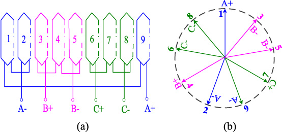
Proposed HEMFMM winding connection. (a) Stator armature winding connection, (b) stator armature winding connection star slot diagram.
It can be seen from Fig. 1 and Fig. 2 that the proposed HEFMM topology has the following advantages: (1) The hybrid excitation is introduced into the field modulated motor, and the magnetic flux of the motor is adjustable by controlling the DC excitation winding [20,21]. (2) The external rotor topology design is conducive to the design of vernier motor with multiple permanent magnets, and can be directly combined with the electric vehicle hub. The rotor permanent magnet part adopts the alternate pole design to solve the problem of excessive use of permanent magnets in existing MFMMs. It can save the use of permanent magnets and increase the mechanical strength of the rotor permanent magnet part.
The proposed HEMFMM adopts armature and DC windings into the inner stator and FPMs, which means that the magnetic field distribution generated by the stator armature winding can be changed by the additional DC windings. At this time, the PMs can be considered as the tooth in the traditional magnetic gear, that is, a small position change on the rotor can lead to a large magnetic flux change for the whole machine. Based on the specific rules between the combination of pole and slots, the magnetic field of the stator armature winding with low pole pairs is modulated, thus, the harmonic magnetic field component that can match and interact with the high pole number PM magnetic field can be obtained. It means that the goal of low speed and high torque without increasing the machine volume and slot number can be obtained.
Consequently, the high-to-low speed gear ratio of the proposed machine is given by [8]:
For the proposed machine, there are nine stator teeth, two FMPs are uniformly distributed on each stator tooth, and eighteen FPMs are uniformly distributed on the whole stator. According to the magnetic gear modulation principle, the transmission ratio is 4.5. When the outer rotor speed is 200 rpm, the space rotating magnetic field speed of the stator armature winding is 900 rpm, which means that the outer rotor speed is only 1/4.5 of the space rotating magnetic field speed of the inner stator armature, which can achieve the magnetic field growth effect.
Electromagnetic torque of the proposed HEMFMM T
e
consists of three parts, namely, the PM torque component T
pm
generated by the action of PM flux linkage and armature winding current, the reluctance torque component T
r
generated by the change of winding inductance, and the torque component T
f
generated by the action of DC excitation winding flux linkage and armature winding [22,23], which shows as
When HEMFMM works at low-speed area, the reluctance torque is used as a part of the electromagnetic torque to increase the output torque and no excitation current is applied. It can realize the direct drive operation at low speed and large torque through the magnetic flux modulation. When it works at the high-speed area, the DC excitation winding is energized, and the air gap magnetic density of the machine can be effectively suppressed to achieve high-speed field weakening control operation.
Finite element modeling
For the proposed HEFMM, its remarkable feature is that there are two kinds of windings at the same time, so its working principle is different from that of traditional PMSM. Considering its unique topology and the working principle of flux modulation, the finite element method is used to calculate and analyze it [24].
The armature current in the proposed machine meets the following condition
The motion equation of the proposed machine is given as
The finite element model of the proposed motor can be obtained by combining Maxwell equations of Eq. (4) to Eq. (6).
The main specifications of the proposed HEMFMM is shown in Table 1.
Main specifications of the proposed HEFMM
Main specifications of the proposed HEFMM
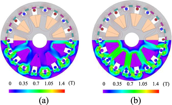
When no current passes through the machine excitation winding, that is, when it is under no excitation, no-load magnetic field distributions of the proposed HEMFMM under different rotor positions is shown in Fig. 3.

No-load magnetic field distributions with no excitation current. (a) Initial position, (b) twenty-degree movement.
It can be seen from Fig. 3 that although the field modulated motor is a branch of PMSM, its spatial magnetic field distribution is quite different from the traditional PMSM. The pole pairs of the stator windings of the traditional PMSM spatial magnetic field are equal to the pole pairs of the permanent magnet, while the pole pairs of the stator windings of the PMVM are no longer equal to the pole pairs of the permanent magnet. For the proposed HEFMM, the permanent magnet pole pair is 14, and the stator winding space pole pair is 4.
Figure 4 shows the no-load magnetic linkage and back-EMF waveform of the none excitation winding. The magnetic linkage and back-EMF waveform of the HEMFMM have a high sinusoidal degree, which is suitable for brushless AC drive, and its conduction angle is 180 degree.
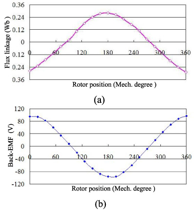
Waveforms of the proposed HEMFMM. (a) No-load flux linkage. (b) Back-EMF waveform.
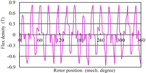
The radial flux density distribution of the machine is shown in Fig. 5. There are 14 air-gap magnetic density cycles in 360 degree, which verifies the design of 14 pairs of PMs of the machine. The corresponding harmonic spectrum is shown in Fig. 6. It can be seen from Fig. 6 that except for the 14th fundamental component in the air gap flux space harmonics, the 4th harmonic component in the high-speed low harmonic has the largest amplitude. The 4th harmonic corresponds to the transmission ratio of 4.5, as an effective harmonic component, which is part of the output torque. It verifies the principle of magnetic flux modulation. In addition, it can be seen from Fig. 6 that the peak value of air-gap flux density of the proposed HEFMM is higher than that of the traditional alternating pole PMSM, which verifies that the flux modulation effect is helpful to improve the machine output torque, so as to increase the torque density.
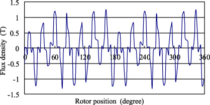
No-load radial air-gap flux density distribution.

No-load radial air-gap flux density harmonic spectrum.
The peak values of output torque change with the increase of electrical density as shown in Fig. 7. It can be seen from Fig. 7 that the output torque of the machine increases with the increase of current density from 4 A/mm2 to 6.5 A/mm2. When the current density changes from 4 to 6 A/mm2, it almost changes linearly, while when the torque exceeds 6 A/mm2, the torque increase is not obvious. At the same time, considering the heat dissipation problem, the electrical density of the machine is 6 A/mm2.
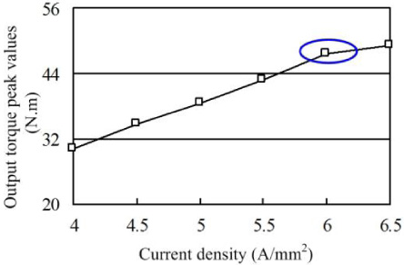
Torque peaks with the variations of different current densities.
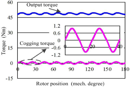
HEFMM torque characteristics.
The steady state output torque and cogging torque characteristics of HEFMM are shown in Fig. 8. It can be seen from the figures that the designed machine has a high output torque, the average torque reaches 47.5 Nm, and the torque density is higher than the variable flux vernier machine proposed in the literature [19]. In addition, the cogging torque of the machine is 0.98 Nm, which is only 1.9% of the steady state torque. It is verified that the multi-pole fractional slot structure is helpful to reduce the cogging torque of the machine.
When the excitation current is applied, the magnetic field line and magnetic density distribution of the HEMFMM are shown in Fig. 9. It can be seen that the magnetic density distribution is greatly affected after the excitation current is applied to the machine.
HEFMM magnetic flux distribution with excitation current. (a) Initial position (b) twenty-degree movement.
After the excitation current is applied, the distribution of HEFMM air gap magnetic density is shown in Fig. 10. Compared with Fig. 5, the air gap magnetic density of the machine is significantly reduced compared with that without the excitation winding, which proves the effectiveness of magnetic field weakening control.
HEFMM air-gap flux density distribution with excitation current.

HEFMM test system with (a) prototype test platform and (b) control system.

Different back-EMF waveforms with excitation current values of I f are 0, 0.5 A and −0.5 A. (a) n = 100 rpm (b) n = 150 rpm (c) n = 200 rpm.
With the purpose of verifying the correctness of simulations results with the proposed HEMFMM, a 1 kW prototype and its testing platform were established, as shown in Fig. 11.
Figure 12 shows the test waveforms of back-EMF when the excitation currents is 0, 0.5 A, −0.5 A and machine operation speeds are 100 rpm, 150 rpm and 200 rpm, respectively [24–26]. It can be seen from the Fig. 12 that the back-EMF values modify obviously when the excitation current values are changes. When the excitation current values are 0.5 A and −0.5 A, the average field weakening and increasing amplitude are 52.9% and 33.7%, respectively, which can meet the needs of wide speed range regulation. It is worth noting that, compared with the traditional hybrid excitation PMSM, the proposed HEMFMM in this paper has more obvious effect in the field weakening, and the magnetic field saturation of the machine is easier to be obtained caused by the increase of magnetic field [27].
Figure 13 shows the back-EMF waveform of the proposed machine at the rated speed of 214 rpm without DC excitation. It can be seen from the figure that the three-phase back-EMF waveforms are symmetrical in phase and the waveforms are sinusoidal. The effective value of the fundamental wave of the HEMFMM back-EMF is 88.6 V, and its harmonic distortion rate THD is 1.56%.

Back-EMF waveform with no excitation current at rated speed.
Based on introducing of hybrid excitation principle into the magnetic field modulation machine, a new type of HEMFMM is presented and designed in this paper. Based on the magnetic field modulation, the HEMFMM mathematical model was deduced and its FEA model was established. According to the magnetic field adjusting property of HEMFMM, one DC excitation control method for HEMFMM was presented. The operating performance of the machine was investigated in the entire operating region. Both simulation and experimental results verify the validity of the proposed machine performance, and the following conclusions could be drawn:
(1) The stator adopts a multi tooth split pole structure, which can effectively reduce the number of stator slots and provide more space to accommodate the armature winding. The operation range of the proposed machine is enlarged without increasing the machine volume and the number of stator slots.
(2) By separating the DC excitation winding from the stator slot, the utilization of stator space can be effectively improved, thus effectively improving the motor torque density.
(3) The concentrated winding structure can effectively shorten the armature winding end and reduce the motor loss, while the multi-pole fractional slot helps to reduce the motor cogging torque.
(4) One prototype with 1 kW rated power is designed and the corresponding characteristics are tested. The experimental results show that the proposed machine has high torque output at low speed, small cogging torque, and good dynamic field weakening speed regulation capacity, which has a good application prospect in the field of low-speed direct drive for EVs.
Footnotes
Acknowledgements
This work was supported by Scientific and Technological Program of Henan Science and Technology Agency (242102241051), Key Innovation Projects for University Students (202311517009), Key Research Projects of Higher Education Institutions in Henan Province (24A470002, 24B510001), Ministry of Education Collaborative Education Program (230702910213146) and the Scientific Research and Cultivation Foundation of Henan University of Engineering (D2022012).