
Abstract
This paper proposes a variable-flux Vernier machine with dual consequent pole configuration to realize wide speed-range operation. The rotor has a consequent pole structure with high coercive force (HCF) material composed permanent magnets (PMs), whereas the stator has PMs positioned between the flux modulation poles. Stator-mounted PMs are made of low coercive force (LCF) materials that can be easily demagnetized or magnetized for variable-flux machines. By changing the magnetization state of the LCF PMs, suppression of magnetic flux was increased to reach higher-speed operation. Demagnetization of the stator LCF PMs reduced the total magnetic flux to reach a higher speed range. In addition, reverse magnetization allowed the machine to achieve further speed-range enhancement. The proposed machine was improved with a parametric selection process. Machine performance of each magnetization state was analyzed by way of speed torque curves and efficiency maps.
Introduction
The consequent pole structure offers machines that have the advantages of material cost reduction and air-gap flux density enhancement by simply substituting magnetic poles with iron poles alternately [1]. In particular, a dual consequent pole machine was recently proposed by Yang [2]. The concept of the topology in [2] was to place high coercive force (HCF) permanent magnets (PMs) on the rotor with consequent pole arrangement, and low coercive force (LCF) PMs on the stator teeth with consequent pole order. In [2], the demagnetization flux of the LCF PMs was either enhanced or weakened by additional magnetizing coils separated from the armature windings. This work concluded that dual PM excitations can be combined to cause synergies with variable-flux machine features.
A variable-flux machine suggests a novel method to vary the magnetic flux of the machine by field weakening of wound synchronous machines or flux weakening of PM machines. Rather than changing the coil flux by weakening the field current (field weakening method) or injecting d-axis current to weaken the magnetic flux (flux weakening method), a variable-flux machine alters the magnetic flux of the PMs by demagnetizing or magnetizing the PM itself. This unique concept was first suggested by Ostovic [3]. With this new possibility, many researchers have become interested, and they have presented numerous methods to realize the idea in different ways [4–7].
The needs of a high-performance motor have led many researchers to focus on the low-speed, high-torque Vernier machine. The Vernier machine shows exceptional performance in low-speed applications because of its harmonic utilization structure. It uses a particular combination of stator slots and magnet poles, which cause the Vernier effect. This results in higher back-electromotive force (BEMF) than typical PM synchronous machines (PMSMs) [8–11]. However, a Vernier machine is unsuitable for high-speed applications because of its high inductance. These characteristics cause a low power factor, high iron loss, and narrow speed range [12].
This paper proposes a variable-flux, dual consequent pole Vernier machine to achieve a wide speed range. The dual consequent pole topology was adopted to utilize the LCF PMs by varying the total magnet flux without additional dc winding on the stator. The use of demagnetizing current from the armature winding was adopted to vary the total magnet flux. Demagnetization state and reverse magnetization state were suggested and analyzed to show the machine’s performance at each state. The analysis results demonstrate the possibility of a wide-speed-range Vernier machine.
Machine topology and operating principle
The basic topology of the proposed machine is shown in Fig. 1. The design of the machine was determined through a load-distribution method to balance the torque production, losses, and efficiency, because Vernier machines typically have very high magnetic load.
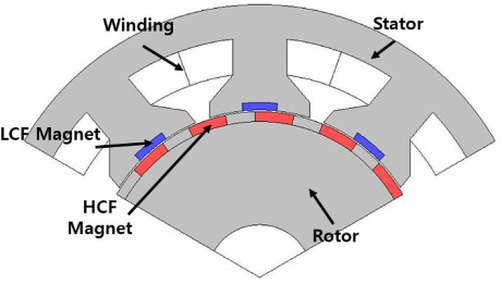
Outline of the proposed machine.
The rotor consists of alternately positioned HCF PMs with iron poles. This arrangement of PMs is called consequent pole [1]. Unlike the conventional surface PM (SPM) type, the consequent pole type offers high air-gap flux density because of the increased permeance and less cogging torque because of the decreased magnet quantity. Additionally, the dual consequent pole design offers the usage of stator-positioned magnets to further enhance the machine by aiding the main magnetic flux. In the dual consequent pole configuration, PMs are placed on both the rotor and stator with a consequent pole arrangement. Stator-positioned LCF PMs are positioned between flux modulation poles (FMPs), and HCF PMs were positioned between rotor iron poles. This configuration improves demagnetizing the target PM directly by armature winding with no air gaps. The stator consists of stator teeth with FMPs and LCF PMs embraced between the FMPs. These two different PM positions compose the dual consequent pole configuration. Windings of the machine were selected to be concentrated windings for simplicity of the winding process. Specifications of the proposed machine are shown in Table 1.
Specifications of proposed model
A specific pole-slot combination of the proposed machine was selected to achieve the Vernier effect. To exploit the benefits of the high power of Vernier machines, the specific equation of the pole-slot combination was used as shown in Eq. (1) [13], where N
P
indicates the pole-pairs of the magnets, N
f
the number of FMPs, and P
s
the armature pole pairs.
According to Eq. (1), various combinations can be established. In this work, a combination that can be constructed with three armature pole pairs was selected as the basic model. The combination was selected according to the aim of the proposed machine, which required proper FMP number for stator PM placement, limited inverter voltage, and good flux weakening capability. Several combinations were compared, and the best combination of nine stator slots and 30 rotor poles (9S30P) with 18 FMPs was selected.
The main idea of the proposed machine is to change the magnetization state of the stator-positioned LCF PMs to use the concept of variable-flux machines. In particular, in the proposed machine, reverse magnetization is suggested, which magnetizes the LCF PMs in the opposite of the initial direction. This suppresses the magnetic flux of the HCF PMs, which increases the motor phase voltage with the opposite magnetic flux of the LCF PMs, consequently further increasing the speed range.
Figure 2 shows the magnetic flux directions from each LCF and HCF PM with different magnetization states of the LCF PMs. In Fig. 2(a), the initial state of the machine is presented, where the LCF PMs have full magnetization. The magnetic flux of the LCF PMs aids the main magnetic flux from the HCF PMs to enhance the torque production of the machine. Figure 2(b) shows the perfect demagnetization state of the machine’s LCF PMs. In this case, the magnetic flux from the LCF PMs, which builds up the motor phase voltage with HCF PMs, is removed. This realizes overall magnetic flux reduction in the machine. Finally, in Fig. 2c, the reverse magnetization state of the LCF PMs from the initial magnetization direction is illustrated. Magnetic flux from the LCF PMs suppresses the magnetic flux from the HCF PMs by providing flux in the opposite direction. By further suppressing the magnetic flux, the machine is able to operate at a higher speed with limited inverter options.
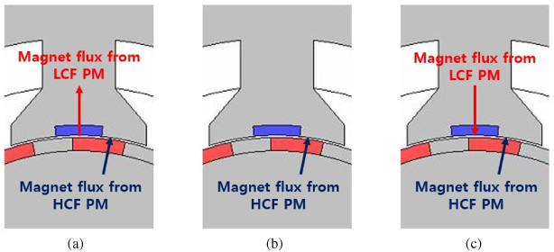
Magnet flux directions according to LCF PM magnetization state. (a) Full magnetization (b) Demagnetization (c) Reverse magnetization.
To demagnetize and reverse magnetize the LCF PMs, d-axis current was applied from the armature windings. Armature currents needed for demagnetization, and reverse magnetization were able to be calculated from the magnetic field intensity value H demag , and H reverse , respectively. These magnetic field intensities were exhibited in B-H curve of LCF PM in Fig. 3(a). The d-axis current was applied with a millisecond scale current pulse. Example of the current pulse was shown in Fig. 3(b). With the demagnetizing current pulse applied, the resultant back-EMF of the machine would be lessened as the total magnet flux has been decreased as shown in Fig. 3(c). Contour plot of demagnetization ratio was shown in Fig. 3(d) to exhibit the successful demagnetization of LCF PMs.
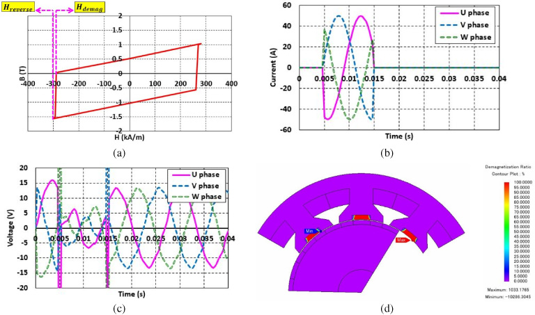
Example of demagnetization. (a) B-H curve of the LCF PM (b) Demagnetizing current pulse (c) Resultant back-EMF after demagnetization (d) Contour plot of demagnetization ratio.
The concept of variable flux was utilized in the proposed machine to demagnetize or magnetize the stator LCF PMs by using a demagnetizing current from the armature windings. In order to utilize variable flux, the selection of LCF PM was essential to trade off performance and cost-effectiveness.
The proposed machine was compared with different stator LCF PM materials, as shown in Table 2. The compared LCF PMs were Alnico, SmCo, and ferrite. Even though Alnico had the lowest coercive force, which can be magnetized and demagnetized most easily, it showed too-low back-electromotive force (BEMF) due to its low magnetic operating point. SmCo showed somewhat higher BEMF than the ferrite. However, although it had relatively less coercive force than NdFeB, it was still not easy to change the magnetization state with an armature current. In the ferrite case, the machine performance was fair, but less than that of SmCo. Nevertheless, in consideration of the lower coercive force and lower cost, ferrite was selected as suitable for the stator-positioned LCF PM.
Back-EMF and motor phase voltage of different LCF PMs
Back-EMF and motor phase voltage of different LCF PMs
Parametric analysis of the proposed machine was executed to improve the machine’s performance. Selected parameters were magnet angle ratio of the rotor-positioned LCF PMs and magnet thickness of the stator-positioned HCF PMs. Selected parameters are indicated in Fig. 4. Magnet angle ratio is defined as the ratio of magnet angle to iron pole angle:
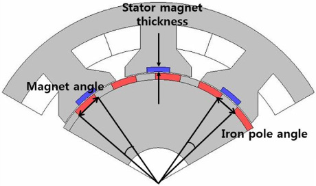
Parameters for parametric analysis.

Parameters for parametric analysis. (a) Performances according to magnet angle ratio (b) Performances according to magnet thickness.
The analysis results were obtained with the presence of the LCF PMs. Figure 5(a) shows that average torque increases to a ratio of 1.4, then decreases continuously. This was caused by saturation of the iron pole part of the consequent pole rotor, because most of the magnetic flux was focused in the iron pole because of its high permeance and small air gap. The motor phase voltage of Fig. 4a shows a relatively continuous increase compared with the average torque. Figure 5(b) shows the motor phase voltage and average torque resulting from different magnet thickness of HCF PMs. Even though the average torque presents a peak value near 7.4 mm thickness, the motor phase voltage shows irregular patterns of increase and decrease. The irregular patterns of motor phase voltage were caused by saturation combined with the dual consequent pole configuration. Finally, the magnet angle ratio of the LCF PMs was chosen to be 1.4 for the highest torque, and the magnet thickness of the HCF PMs was chosen to be 5.2 mm for the smallest motor phase voltage without excessive saturation.
Air gap flux density
The harmonic spectrum of air-gap flux density in different magnetization states at load condition was analyzed as shown in Fig. 6. The full magnetization state, demagnetization state, and reverse magnetization state exhibit quite different values at each important harmonic order, including the 3rd, 6th, 9th, 12th, 15th, and 18th. Because the proposed machine has three armature pole pairs, 15 magnet pole pairs, and 18 FMPs, the 15th harmonic component exhibits the largest value in the harmonic order of magnetic flux density as the main flux. This harmonic component produces torque by cooperation with the modulation flux, which was the 3rd harmonic order equal to the armature pole pair number. The 3rd harmonic order, which is the modulation flux harmonic order, had increased, and the main flux harmonic order (15th) decreased as the magnetization status changed from the full magnetization state to demagnetization state to reverse magnetized state. Additionally, it can be seen that the 9th harmonic order, which is equal to the number of stator slots, decreases extremely as the stator PM demagnetizes.
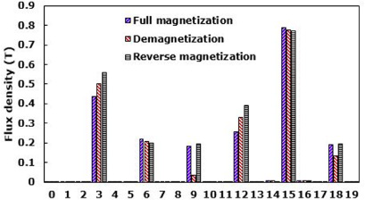
Harmonic spectrum of airgap flux density at load condition.
The effect of the stator PMs’ existence on the proposed machine can also be considered because the full magnetization state and the demagnetization state are equal to stator PM existence and non-existence. It may seem that the torque production might increase with absence of the stator PMs, because the 3rd harmonic order spectra decreased dramatically. However, this is not certain because of the main flux harmonic order (15th) decrement, because most of the contribution to the torque production is from the main flux. The contribution of the stator PM on torque production is discussed in the next section.
To show the performance of the proposed machine operating at a wider speed range, speed-torque curves of the machine were generated. According to the stator-positioned LCF PMs’ magnetization state, each speed-torque curve is compared in Fig. 7. As shown in Fig. 7, as the magnetization state changes from full magnetization through demagnetization and to reverse magnetization, operating speed range increased dramatically. The demagnetized state of the LCF PMs resulted in increasing the speed range to 13% wider. However, the reverse magnetization state of the LCF PMs showed that the speed range can be extended up to 63% higher than the maximum speed of initial full magnetization state.
As can be seen in Fig. 7, the torque production of the full magnetization state (i.e., the presence of the stator PM) was relatively higher compared to the demagnetization state (i.e., the absence of the stator PM), and even higher compared to the reverse magnetization state. It can be concluded that the main flux reduction affected torque production more than the modulation flux increment.
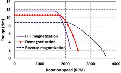
Speed torque curve according to different magnetization state.
Efficiency was calculated on the basis of machine efficiency. Copper losses and iron losses were considered as heat loss. Output power was calculated by multiplying machine speed and torque. The equation used for the calculation was
Figure 8 shows the efficiency maps for each magnetization state. At the initial state of the machine, when the LCF PMs are fully magnetized, efficiency up to 70% is achieved only near 2000 rpm (presented as point A in Fig. 8a). As the speed range increases at the reverse magnetization state, the efficiency of higher speeds improves up to 70% over 3000 rpm (presented as point B in Fig. 8c). Consequently, by utilizing different magnetization states, the proposed machine can achieve efficiency higher than 70% from 250 rpm to 3000 rpm, which is an approximately 50% wider range than that of the initial magnetization state.
The overall efficiency can seem somewhat lower than that of conventional machines. However, Vernier machines have inherently higher efficiency at low speed compared to conventional machines. This allows the proposed machine to be highly suitable in applications in which the machine mainly operates at low speed, but occasionally operates at high speed, such as direct-drive electric vehicle propulsion systems.
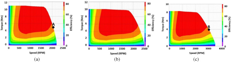
Efficiency map according to different magnetization state. (a) Full magnetization state (b) Demagnetization state (c) Reverse magnetization state.
A dual consequent variable-flux Vernier machine is proposed for wide speed-range operation. A dual consequent pole configuration is used to take advantage of the structure to vary the magnetic flux of the LCF PMs on the stator. In particular, the variable-flux feature is further extended to reverse magnetize the LCF PMs to further widen the speed range. The basic structure of the machine consists of the combination of stator slots and rotor poles to take advantage of the Vernier effect. To achieve higher performance of the proposed machine, parametric analysis was performed for the magnet ratio of the LCF PMs and magnet thickness of the HCF PMs. FEM analysis was performed to provide speed-torque curves and efficiency maps. The proposed machine showed an extension of the speed range up to 63% and improvement of efficiency by utilizing the variable-flux feature. With further improvement, the proposed machine shows high suitability for adoption in electric vehicle applications.
Footnotes
Acknowledgements
This work was supported in part by the BK21PLUS Program through the National Research Foundation of Korea within the Ministry of Education, and in part by the National Research Foundation of Korea (NRF) in a grant funded by the Korean government (Ministry of Science) (No. NRF-2017R1A2B4007697).