
Abstract
This article presents an angular position control, based on the Gaussian function, of a Magneto-Rheological fluid disc brake (MR brake) driven by a DC motor. Our proposed control strategy is to apply a continuous magnetic flux density to the MR brake, which will be maximum when the proportional controller of the DC motor reaches the desired position to brake the hybrid device. The MR brake controller activates a braking torque that adopts the behavior of the Gaussian function instead of a pulsed braking torque as provided by other commonly used controllers (On-Off controllers). The response of the MR brake controller, which is presented in a closed-loop feedback system, depends on the angular position error of the shaft and a tuning parameter representing the critical angular position at which the magnetic flux density, which is applied to the MR brake, reaches 60.65% of its maximum value. The advantage is to avoid knowing the dynamic parameters, such as the inertia of the mechanical device or its speed, and to reject these perturbations by a simple tuning parameter of the MR brake. To show the effectiveness of the proposed controller, the dynamic model of a slider-crank mechanism is considered. The results showed similar behavior as conventional controllers, where overshoot and oscillations were minimized. This behavior has been obtained in other research articles using controllers that require a greater amount of data processing.
Introduction
One of the most widely used active devices in robotics and mechanical engineering is the electric motor, which is used to insert or dissipate energy from electromechanical systems in a controlled way. Robotic manipulators and some mechanisms are usually used in the link joints to generate movement in a controlled way. This is achieved through the implementation of active controllers, such as the Proportional-Integral-Derivative (PID) controller. In some cases, this control requires to be performed as quickly as possible, which complicates the performance of the electric motors since this involves the insertion and dissipation of energy in a reduced time, which could cause sub-damped behaviors, generating oscillations around a target position. For this reason, several types of electric motors and controllers have been implemented, and various types of tunings of their parameters to minimize the overshoot and oscillations of the manipulators and mechanisms. However, due to the nature of active devices and their controllers, they are not able to decrease this behavior completely since by minimizing overshoot and oscillations, the reach time of the target position tends to increase.
To address this issue, semi-active devices can be used, which dissipate energy from mechanical systems, providing stability to active control systems [1]. One such device is the well-known Magneto-Rheological brake (MR brake). This brake presents a quick response and a wide range of controllable braking torque since it uses of an intelligent material: Magneto-Rheological fluid (MR fluid). MR fluids are mechanical suspensions containing micrometric particles (0.03 μm–10 μm), mainly spherical, ferromagnetic, or paramagnetic composed of pure iron, carbonyl iron, or cobalt, dispersed in a non-magnetic liquid, usually mineral oil to which additives are added to improve its performance [2–4]. The MR fluid is categorized as a non-Newtonian fluid since it exhibits rheological behavior when exposed to magnetic fields, alternating its behavior between a viscous liquid and an elastic solid, in a controllable way [5], with a response time of fewer than three milliseconds [2]. MR brakes have become easily adaptable devices to work in conjunction with active devices, such as DC motors, resulting in a hybrid action device that provides a quick response with insertion and dissipation of more energy. Consequently, the mechanical performance of these hybrid devices has been studied in several works using different torque, speed, and position control strategies. In articles related to angular speed and torque control, control strategies using On-Off controllers [6], PID controllers [7–9], sliding mode control (S.M.C.) [10,11], non-linear optimal control based on the state-dependent Riccati equation (S.D.R.E.) [12], adaptive torque feedback control [13], and fuzzy logic control [14] have been implemented. On the other hand, among the articles related to the angular position control of these hybrid devices, Lima et al. [15] tested the effectiveness of a torque controller obtained through the S.D.R.E. to control the position of a robotic manipulator, and Gonenc and Gurocak [16] obtained the necessary braking torque to stop the rotation of the device in the desired position through the application of an angular position control algorithm that uses a Proportional-Integral (PI) controller and a load inertia estimator. Also, the angular position control of robotic manipulators driven by pneumatic artificial muscles (P.A.M.) [17] has been studied through MR brakes placed on the joints, creating other hybrid devices. In this case, several methods of MR brake position control have also been presented: On-Off control [18]; inner model control (I.M.C.) [19], which considers the dynamic characteristics of artificial muscle; MR brake viscosity coefficient control [20]; control dependent on the angular speed of the joint [21,22]; a controller that considers the estimation of the kinetic energy of the arm, as well as the elastic energy of the P.A.M. to generate the required braking torque of the MR brake [23]; and a controller that considers the desired torque of the arm for safe human-robot collaboration through the use of MR brakes [24].
The control approach presented in this paper is based on the adaptation of the Gaussian function and its tuning with a proportional controller to control the angular position of the shaft of hybrid devices composed of a DC motor and an MR brake. To test the effectiveness of the controller, the dynamic model of a slider-crank mechanism of one degree of freedom is used.
System dynamics
Extended dynamic model of the mechanism
The following equation gives the dynamic model of the mechanism-brake system shown in Fig. 1.
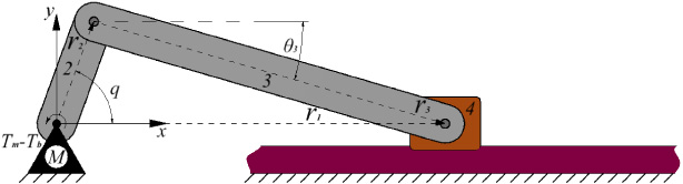
Diagram of the mechanism—brake system.
This section presents the design and configuration of the MR brake, as well as its braking torque analysis, which is part of the dynamic model shown in Eq. (1). It is well-known that the braking torque of an MR brake is presented in two states: torque in the on-state, and torque in the off-state. Torque in the on-state is induced when MR fluid is under the influence of a magnetic field, while the torque in the off-state is induced due to the natural viscous properties of the fluid and the shear rate of the rotating disc, with or without the influence of a magnetic field. Most of the torque induced by the MR brake, which is also easily controllable, is presented in the on-state. Figure 2 shows the internal configuration of the designed MR brake, while its most important components are listed in Table 1.
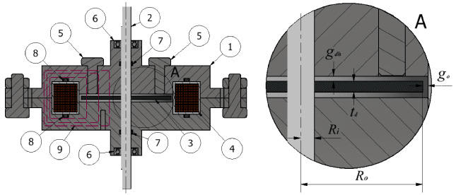
Internal configuration of the MR brake.
Main components of the MR brake
The MR fluid is in the gap between the fixed housing and the end-faces of the rotating disc, so when rotating, shear stresses are induced, which are transmitted to the shaft, generating a braking torque. In this work, for the torque analysis of the MR brake, it is assumed that the MR fluid is in a laminar steady motion and follows the behavior described by the Bingham plastic model. The effects of gravity on the fluid and centrifugal force are not considered, while the friction generated by the O-rings placed on the shaft is considered.
Bingham plastic model, which represents a very close approximation of the shear stress acting on an MR fluid, is shown in Eq. (2), where τ
y
and 𝜂 are the magneto-rheological variables of the MR fluid and represent dynamic yield stress and dynamic viscosity, respectively, and 𝛾 is the shear rate.
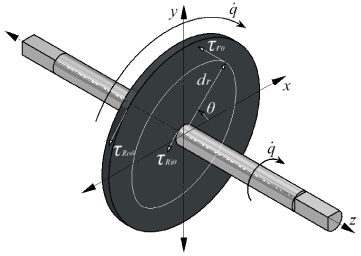
Induced shear stresses.
Hybrid device position control block diagram.
According to Eq. (9), the dynamic yield stress depends directly on the magnetic flux density, which is why it is important to derive the function that represents the change from voltage to magnetic flux density in the MR brake coil. For this purpose the equation of the magnetic field of a coil will be used:
Control system
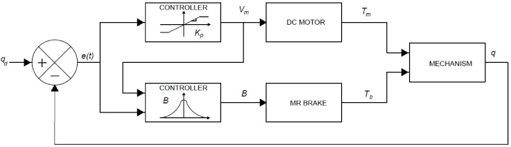
An angular position controller of a hybrid device composed of a DC motor and a MR brake is proposed, this controller is divided into two parts: a proportional controller applied to the DC motor and a novel controller, based on the Gaussian function, applied to the MR brake. In the latter controller, the characteristic parameters of the Gaussian function have been adapted so that the applied magnetic flux density, which induces the MR effect of the brake, adopts the characteristic shape of the function. This behavior will be dependent on the position error and a tuning parameter that will indicate the critical position at which the magnetic flux density must reach 60.65% of its saturation value before reaching the target position, resulting in a smooth and continuous activation of the applied magnetic flux density and not abrupt as On-Off controllers do. In this work, tests were done to find the critical position. The system block diagram is shown in Fig. 4.
Figure 5 shows the response of the angular position of a DC motor, activated by a PID controller, compared to the response of the hybrid device, activated by the proposed controller.
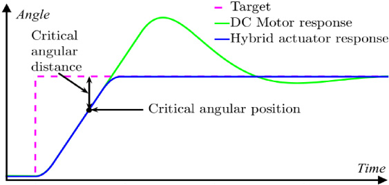
Hybrid actuator response.
The Gaussian function is expressed as follows:
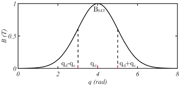
In order to stop the hybrid device at the desired position, an MR brake controller is required to activate the MR effect so that it increases its braking torque when the system approaches the desired position and decreases it when the system moves away from this position. To achieve this, the Gaussian function has been adapted so that the magnetic flux density, which controls most of the braking torque of the MR brake, exhibits the behavior of a Gaussian function. Its parameters have been adapted from the Eq. ((12)) as follows:
Gaussian behavior of magnetic flux density.
In order to test the effectiveness of the proposed controller, two tests with different target signals are considered: the first test with a step-type signal, with q0 = 9π∕8 rad and q d = 21π∕8 rad, where q0 is the initial angular position; and the second test with an irregular square wave type signal, which represents a movement routine that switches between twelve target positions consecutively (radians): P1 = 9π∕8, P2 = 21π∕8, P3 = P1, P4 = 15π∕4, P5 = −3π∕2, P6 = P4, P7 = −P1, P8 = 3π∕8, P9 = −P1, P10 = P8, P11 = 9π∕4, P12 = P4. Both target signals have a pulse width of 2.5 s. For the tests, the parameters of the mechanism and the MR brake shown in Table 2 and Table 3, respectively, are considered. In Table 2, r n , m n , and Icm n are the length, mass, and moment of inertia of the n-link of the mechanism, respectively. The maximum torque of the DC motor considered is 1.72 Nm, with a maximum speed of 4π rad/s, while the maximum torque of the MR brake (T bMAX ) is approximately 2 Nm. The experimental setup is shown in Fig. 7.
Mechanism parameters
Mechanism parameters
MR brake parameters

Experimental setup.
The MR fluid considered in this work is the MRF-132DG, manufactured by LORD® Corporation, which is magnetically saturated with a magnetic flux density of 1.65 T. The rheological properties of the fluid at zero magnetic field and magnetic saturation (Table 4) are obtained by an experimental process in [27].
Rheological properties of MRF-132DG [27]
The control tests were first simulated to find the optimal values of q
c
and kp more easily, and then they were performed experimentally. Simulated control tests were performed using simulation in Matlab’s Simulink® software, with the ordinary differential equation solver “ode4 (Runge–Kutta)”, and a fixed sampling time of 1 × 10⁻⁴s. To define the optimal values of the parameters kp (proportional gain of the proportional controller) and q
c
, where the steady-state position error is minimal, the integral square error (ISE) criterion was implemented. Figure 8(a) shows tuning using the ISE criterion, where 𝜉 = q
c
∕kp and

Proportional - Gaussian controller tuning.
The results of the simulated control tests are shown in Fig. 9. Figure 9(a) shows the response of the hybrid device with the proposed controller when the step-type target signal is activated, compared to the response of a DC motor with a PID controller. It can be observed how the hybrid device minimizes overshoot and oscillations. In addition, the behavior of the applied magnetic flux density can be observed, whose shape, dependent on the position error, is governed by the Gaussian function, which is tuned to the torque of the DC motor by the ratio 𝜉. It can be noticed that the torque of the MR brake presents a gradual increase as the position error decreases. On the other hand, Fig. 9(b) shows the response to the reference input of the irregular square wave type. It can be noted that the proposed controller for the hybrid device presents a better response to angular position change than the response of a DC motor operated by a PID controller.
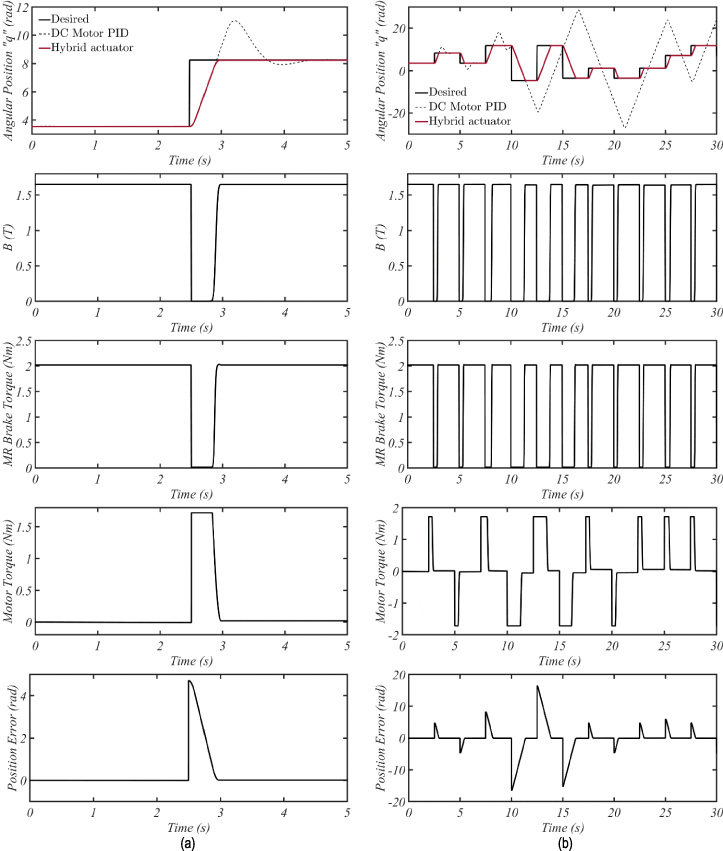
Hybrid actuator response for (a) step-type target signal and (b) irregular square wave type target signal.
The steady-state position error was below 0.01745 rad in each test performed. It should be noted that the distances between angles of the tests shown in this paper were chosen randomly, but with an angle between target positions ≥π∕2 rad.
Figure 10 shows the behavior of the magnetic flux density, applied to the MR brake, concerning the change of angular position of the shaft, when the hybrid device follows the step-type target signal of the test shown in Fig. 9(a). It can be noted that B reaches 60.65% of its maximum value when q = q d − q c , and 100% when q = q d .

Behavior of the applied magnetic flux density of the test shown in Fig. 8(a).
Finally, for the experimental tests, it must be considered that the characteristics of the system elements are not ideal, so there could be differences with respect to the simulated tests. However, the final performance of the position control should be very close to the simulated one. Considering the above, the q c and kp parameters were adjusted, with kp = 0.8 and q c = 0.6718, due to the fact that the motor used may show slightly different dynamic characteristics from those considered in the simulation. The results of the experimental control tests are shown in Fig. 11. Figure 11(a) shows the response of the hybrid device with the proposed control strategy when exposed to the step-type target signal, compared with the simulated response. It can be observed that the hybrid device is able to position the system very close to the desired position, with a steady-state position error of less than 0.038 rads. It is also observed that, unlike the simulated hybrid device, it takes a little more time to reach its maximum speed, but the response is still very close to the expected one. Figure 11(b) shows the simulated and experimental response to the irregular square wave type reference input.

Simulated and experimental response for (a) step-type target signal and (b) irregular square wave type target signal.
This behavior has been obtained in other research papers, where controllers that require a greater amount of data processing are used. For instance, in [16], the system was moved from q0 = 0 rads to q d = 15 rads (as shown in their Fig. 5a) under three different inertial loads, obtaining performance results very similar to those obtained in this work, as shown in Fig. 12(a). It can be noted that in [16], the desired position is reached in approximately 0.5 s, 0.8 s, and 1.3 s, with the first, second, and third inertial load, respectively, while in this work, the desired position was reached in approximately 1.25 s. The differences in the reaching times shown in the results could be due to two factors: the different characteristics of the inertial loads used and the dynamic characteristics of the DC motors considered in both works, mainly their maximum speed. Figure 12(b) shows the performance of the hybrid device with a higher step-type target signal than that performed in [16].

Simulated and experimental response for a step-type target signal with an initial value of 0 rads and a final value of (a) 15 rads and (b) 35 rads.
An MR brake position controller based on the Gaussian function was presented. The brake is a physical part of a hybrid actuator: DC motor - MR brake. The Gaussian function has been implemented in the P-controller loop due to the shape-shifting characteristic that only depends on the angular position error and a tuning parameter (q c ). The magnetic flux density B that activates the MR effect of the braking torque has the same behavior as this function. The effectiveness of the controller was tested through the position control of a slider-crank mechanism. The aim was to control the angular position of the input crank, which tracked an irregular square wave type target signal. The results showed that the proposed controller was able to move the shaft to the desired position, minimizing overshoot and oscillations by applying the braking torque of the MR brake, converging the steady-state position error below 0.038 rad.
In this way, our proposed control strategy has an advantage, in that it is not necessary to computationally process a greater amount of data, such as inertia and system speed, to control the position of the hybrid device. Therefore, the main contribution of this work is the proposal of a new position control strategy for MR brakes based on the Gaussian function, which avoids the application of more sophisticated control strategies that incorporate PID controllers, inertia estimators, etc., which require a greater amount of data processing such as the inertia, position, and speed of the shaft. Instead, to perform the same task, the proposed control strategy only needs to computationally process its angular position. For future work, another type of tuning for the proposed controller, as well as new control algorithms, could be considered to improve the performance of the hybrid device.
Footnotes
Acknowledgement
The authors would like to thank CONACYT and COMECyT for funding this work under an internal grant.