
Abstract
In high-temperature continuous forging process, according to the real-time monitoring of workpiece thickness and flaws, the processing parameters can be adjusted accordingly, so we can remove defective components in time, which has essential research value for avoiding the interruption of production line and improving their yield and quality grade. We established a finite element (FE) model of the carbon steel’s laser-electromagnetic acoustic transducer (laser-EMAT) testing process. Based on the simulation model, we analyzed the effects of laser parameters, EMAT parameters, and sample thickness on the detected ultrasonic signal amplitude, and we also achieved the optimized Laser-EMAT design parameters. Subsequently, we developed a high-temperature resistant spiral coil EMAT and measured the high-temperature forging with a thickness of 100 mm and temperatures from 300 °C to 730 °C. Based on the experiments, we researched the effect of specimen temperature on the received ultrasonic wave amplitude. The results show that the excitation efficiency of laser-induced ultrasonic waves improves by decreasing pulse duration, decreasing laser spot radius, and increasing pulse laser energy. The receiving efficiency of the shear wave (SW) detected by the EMAT enhances when reducing the diameter of the EMAT wire and increasing the permanent magnet height. When the radius of the permanent magnet is equal to the radius of the EMAT coil, the receiving efficiency of SW is the highest. As the sample thickness increases, the size of the EMAT should increase accordingly to the acoustic beam divergence for obtaining a higher ultrasonic wave intensity. The amplitude of the SW signal received by the EMAT increases by 679% after the optimization design. With rising carbon steel forging temperature, the SW signal amplitude increases first and then decreases sharply, reaching its maximum at 617 °C, which is 29% higher than at room temperature, and the signal-to-noise ratio (SNR) of the SW is 20.5 dB.
Introduction
In forging process under high temperatures, it is essential to adjust the processing technology parameters based on the components’ defect detection and dimension measurement results. In this way, we can effectively eliminate the defective workpiece with a flaw that exceeds the acceptance criteria, and it can help to improve the qualified production rate and enable the effect of environmental protection manufacturing [1–3]. There are some non-destructive methods for carbon steel samples, including eddy current testing (ET), piezoelectric ultrasonic testing (UT), radiographic testing (RT), air-coupled probes, optical sensors and so on. ET detection depth is often insufficient due to the skin effect. The piezoelectric UT can’t be used as it needs to be in contact with the metal, and there is no suitable high-temperature resistant coupling agent and high-temperature piezoelectric material, so its application in high-temperature forgings detection is still difficult. The RT is inconvenient for on-line detection and moving parts, and has a radioactive effect on humans. The air-coupled probes could be affected by the dense structure inside the workpiece and the uneven temperature field on the workpiece surface when detecting high-temperature forgings, the ultrasonic energy received by the air-coupled probes will become very low. And the frequency of the air-coupled probe is mostly 200, 400, 800 kHz, which is limited. The optical sensor equipment is expensive, the structure is complex, and the requirement for the stability of the detection environment is very high. The rough surface of high-temperature forgings will lead to a very low SNR of the received ultrasonic signals. Therefore, an online non-destructive testing (NDT) method is urgently needed for high-temperature carbon steel forging detection [4,5].
In recent years, many researchers have used laser ultrasonic technology to detect metal and non-metal samples. Compared to the traditional UT method, laser ultrasonic technology has the advantages of non-contact, high sensitivity, and so on, which have been widely used in industrial applications [6–8]. Laser generators are divided into pulsed laser and continuous wave (CW) laser. A lot of research has been done on pulsed laser generated ultrasonic. Zhang et al. [9] characterized porosity and its wave velocity, peak frequency, and wavelet packet energy by laser ultrasonic surface wave, thus achieving quantitative testing of additive manufacturing parts. Xu et al. [10] used the laser ultrasonic imaging method to detect micro defects on the rough surface of SLM components. The SNR of the echo signal increased by 8.2 dB, and the hole flaws with diameters of 50 μm and 100 μm could be successfully detected. Kou et al. [11] studied an improved laser ultrasound detection method with synthetic aperture focusing technology (SAFT), and it can detect a hole with a minimum diameter of 1 mm and a slit with a minimum length of 2 mm. Huang et al. [12] proposed a detection method based on the CNN-LSTM network for guided wave laser ultrasonic scanning. The detection accuracy of 0.5-mm deep crack, penetrating, corrosion, and internal crack flaws were 99.9%, 99.9%, 99.8%, and 99.8%, respectively. Pei et al. [13] successfully detected three EDM cracks with a length of 10 mm and a height of 1 mm, 3 mm, and 5 mm on an aluminum plate with a thickness of 15 mm based on the fiber-phased array laser ultrasonic technique. Jiang et al. [14] proposed a quantitative detection method that combines non-contact laser ultrasonic detection technology and variable mode decomposition (VMD), which could effectively detect cracks of different lengths. The quantitative error was less than 5%. There are also scholars using CW laser to generate ultrasonic. Fei Gao et al. [15] proposed an alternate of long laser pulse induced dual photoacoustic (LDPA) technique using quasi-CW laser excitation, the relationship between the number of laser pulses and the amplitude of nonlinear photoacoustic signal was studied. Imaging results were acquired by raster-scanning over a curved black wire sample based on the LDPA technique by quasi-CW laser. Dario Vangi et al. [16] used a modulable CW laser diode to collect Rayleigh waves from 20 × 20 × 20 mm steel specimens, and a time domain signal processing was employed based on cross-correlation technique between laser input and the received signal, the effects of pulse duration, pulse number, time width of continuous pulses on ultrasonic SNR and center frequency were studied, and then a method to enhance Rayleigh wave was obtained. Huiting Huan et al. [17] introduced the NDT method based on single frequency domain laser ultrasonic (FDLU) by means of implementing radar principles: Linear-frequency-modulated excitation CW laser-beam intensity to perform, the ultrasonic signal was processed by pulse compression method, the established laser ultrasonic radar system could successfully locate the hole defect at the depth of 20 mm. Both pulsed laser and CW laser were used by scholars in laser ultrasonic, but more researchers still use pulsed lasers. Compared with CW laser, the pulsed laser is more flexible in parameter adjustment, can induce high energy ultrasonic waves in a concise time, and the thermal depth is shallow, and the heat output is low. These characteristics of pulsed laser can relatively better ensure that the internal grain size and thickness of the specimen do not change, which is beneficial for the early optimization and verification of high-temperature detection [18,19]. Therefore, the pulsed laser is used in this study.
Electromagnetic acoustic transducer (EMAT) is one of the superior technologies for high-temperature detection because of its non-contact advantage. For example, Lunn et al. [20] designed an SW EMAT to measure the thickness of steel pipe and aluminum below 450 °C and evaluated the feasibility of EMAT scanning detection at high temperatures. Hernandez-Valle et al. [21] used a pulsed-electromagnetic EMAT to detect the thickness of low carbon steel with surface temperatures ranging from room temperature to 250 °C, and the ultrasonic wave SNR reached 10.3 dB. Ren et al. [22] studied the magnetostriction effect of EMAT at high temperatures based on FE simulation and experiment. The results showed that the contribution of the magnetostriction mechanism to the detection efficiency of EMAT increased with the increase in temperature. Zhai et al. [23] studied a high-temperature electromagnetic pulse generator with a double coil structure. They realized the selective excitation and reception of different bulk wave modes at 500 °C by adjusting the configuration relationship between the electromagnetic coil and the EMAT eddy current coil.
There are still many problems in detecting forgings with high temperatures. For example, the amplitude and flight time of the ultrasonic waves will change with the rapidly falling temperature of the sample surface, the energy conversion efficiency, SNR, and resolution are low, and EMAT cannot be placed on the surface of a high-temperature sample for a long time. However, laser ultrasound and EMAT have their advantages in excitation and reception. Compared to traditional UT technology, the ultrasonic signal generated by the laser is stronger, and the bandwidth is wider. In addition, EMAT has a great advantage in receiving signals during high-temperature detection. It not only has low cost and simple structure, but more importantly, it is little affected by the surface complexity of high-temperature forgings, and the influence of surface temperature field of high-temperature forgings on ultrasonic wave propagation can be ignored. Therefore, to solve the problems in high-temperature detection, the advantages of laser and electromagnetic ultrasonic technology can be combined when detecting high-temperature metal samples [24,25].
This study proposed a laser-EMAT detection method for high-temperature carbon steel forging. Based on numerical simulation and experimental verification, we studied the effects of laser parameters, EMAT parameters, and sample thickness on the laser-EMAT detection ability. Some experimental measurements were also conducted to provide the performance of the Laser-EMAT in high-temperature detection. The research provides a theoretical reference for the design of laser-EMAT for high-temperature detection.
Principle of laser-EMAT and experimental system
Principle of the laser-generated ultrasonic waves
Figure 1 shows the energy conversion principle of the laser-EMAT. Different ultrasonic waves can be generated when laser heats metal sample’s surface, such as longitudinal wave (LW), SW, and Rayleigh wave (RW). According to the different laser power densities, the ultrasonic generation mechanism can be divided into the thermoelastic mechanism [26] and the ablation mechanism [27]. The source of the thermoelastic effect is thermal stress, so the thermoelastic effect will act together with the ablation mechanism. The study in this paper only considers the thermoelastic mechanism. Under the thermoelastic mechanism, the sample absorbs a part of laser energy, which irradiates its surface. At the same time, the temperature of the sample rises rapidly, and then the sample expands and produces stress and strain fields to generate the ultrasonic wave.

Principle of the laser-EMAT energy conversion. (a) Ultrasonic waves excited by the laser. (b) Ultrasonic waves received by the EMAT. LW: longitudinal wave, SW: shear wave, RW: Rayleigh wave.
The equation for the ultrasonic displacement field generated by thermal stress is as follows [28]:
When the ultrasonic wave propagates inside the sample and reaches its surface, the particles oscillate and cut the magnetic induction line to generate a source current. The EMAT coil can sense the varying source current, and an induced voltage can be formed in the detection EMAT.
The governing equations of the static magnetic field formed by the permanent magnet on the metal surface are as follows [30]:
The governing equations of the induced voltage V received by the EMAT are [31]:
Laser-EMAT FE modeling
Figure 2 shows an axisymmetric 2D geometry FE model of laser-EMAT established by the commercial finite element software, and its modeling parameters and values are provided in Table 1. The grid of the 45# steel sample and the permanent magnet domain was a mapping mesh, the grid of the coil domain was a free triangle mesh, and the maximum grid size was 0.1 mm. We used a line with a length equal to the radius of the spot to represent the laser excitation region. An energy conversion region with a height of 0.1 mm was set on the upper surface of the sample. The conversion region meshed with nine boundary layers and a stretching factor of 1.2, and the thickness of the first layer was 0.001 mm. The maximum computation step is 0.01 μs. The meshing grids and the computation step in the FE model are optimized to get convergence results. The physical parameters of various materials in the FE model are shown in Table 2. All simulation results are not associated with experimental results.
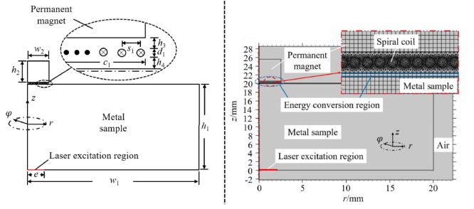
Schematic diagram of laser-EMAT testing modeling.
Design parameters and values of laser-EMAT
Physical parameters of various materials in FE model
The transient cloud diagram of the ultrasonic propagation in the steel sample is shown in Fig. 3. As shown in Fig. 3, SW, LW, and RW are generated simultaneously and propagate in different directions. Figure 4 shows the radial and axial components of the ultrasonic displacement signal. As shown in Fig. 4, when laser duration time v = 8 ns, spot radius e = 4 mm, and laser energy Q 0 = 185 mJ, the peak–peak value of LW is 1.34 × 10⁻¹³ m, and the peak–peak value of SW is 3.25 × 10⁻¹³ m. The SW intensity generated by the pulse laser is larger than the LW intensity.

Transient cloud image of ultrasonic wave propagation in a steel sample.

Ultrasonic displacement signal generated by the laser.
The spot radius e, the laser duration time v and the laser energy Q 0 were changed, respectively. The effects of different laser source parameters on ultrasonic bulk wave displacement are shown in Fig. 5. It can be seen from Fig. 5(a) that the amplitude of the ultrasonic wave decreases gradually with the increase of the spot radius. The larger the spot radius, the smaller the particle vibration amplitude inside the sample and the weaker the generated ultrasonic wave. When the spot radius increases, the descending speed of SW is faster, while the descending speed of LW is slower, indicating that spot radius has a more significant influence on SW propagation. Therefore, the focusing lens can reduce the radius of the laser spot so that the energy of the laser source center point is higher to increase the amplitude of the ultrasonic signal. As can be seen in Fig. 5(b), the received ultrasonic displacement decreases rapidly at first and then gradually becomes stable as the pulse duration time increases. Figure 5(c) shows that with the increase of laser pulse energy, the amplitude of bulk wave displacement increases accordingly. Since the laser power density is proportional to the pulse energy, the amplitude of the ultrasonic wave displacements changed linearly with laser energy which is consistent with theory [32].

Effects of different laser source parameters on ultrasonic bulk wave displacement.
When spot radius e = 4 mm, laser duration time v = 8 ns, and laser energy Q 0 = 185 mJ, the wire diameter d 1 = 0.25 mm, the outer radius of the coil d 3 = 5 mm, the magnet radius w 2 and height h 2 were 5 mm, the open-circuit-induced voltage signal received by EMAT is shown in Fig. 6. The peak–peak amplitude of the SW signal is 17.00 × 10⁻⁷ V, and the LW amplitude is 5.92 × 10⁻⁷ V.

Ultrasonic wave signal received by spiral coil EMAT.
Orthogonal experiments are carried out using orthogonal table L16(44), and the corresponding simulation results are shown in Table 3. The influences of wire diameter, coil outer radius, permanent magnet radius, and height on the SW peak–peak amplitude are shown in Fig. 7 and Table 4.
Laser-EMAT 4 factors 4 level orthogonal experiment table

Effects of spiral coil EMAT design parameters on the received SW peak–peak amplitude. (a) Wire diameter. (b) Coil outer radius. (c) Permanent magnet radius. (d) Permanent magnet height.
As can be seen in Fig. 7(a), the amplitude of the ultrasonic signal received by the spiral coil EMAT gradually decreases with increasing wire diameter, taken as a whole. There are two main reasons. On the one hand, when the diameter of the wire increases, the distance between the permanent magnet and the sample increases, resulting in a decrease in magnetic induction intensity of the sample surface. On the other hand, when the wire diameter becomes smaller, the current density in the wire is more uniform. Therefore, the thinner the wire, the greater the amplitude of the open-circuit-induced voltage received by EMAT.
Figures 7(b) and 7(c) show that, when the outer radius of the coil and the radius of the permanent magnet are equal, the amplitude of the EMAT induced voltage signal rises to the highest point. And their values are closely related to the thickness of the workpiece.
Analysis of the peak–peak amplitude of SW in orthogonal experiment
Figure 7(d) shows that the higher the permanent magnet, the larger the amplitude of the SW signal. The radial and axial magnetic field components generated by the permanent magnet on the sample surface increase non-linearly with the increase of the permanent magnet height. Therefore, the amplitude of the ultrasonic signal increases first and then slowly with the increasing permanent magnet height.
In summary, the order of influence of four design parameters on the SW peak–peak amplitude is wire diameter > permanent magnet radius > permanent magnet height > coil outer radius, the best and worst combinations of EMAT parameters were determined as shown in Table 5.
Combinations of spiral coil EMAT parameter
The laser-EMAT FE models of the steel sample with different thicknesses were established using the optimal laser-EMAT design parameters in Table 5. The thicknesses of the steel sample were 20 mm, 60 mm, and 100 mm, respectively. The ultrasonic signals from the steel samples with different thicknesses are shown in Fig. 8, and the peak–peak amplitudes are shown in Table 6.

Ultrasonic signals from the steel samples with different thicknesses (a) 20 mm, (b) 60 mm, (c) 100 mm.
Laser-EMAT Ultrasonic signal detected with steel samples of different thicknesses
As seen in Table 6, the LW amplitude increases first and then decreases as the sample thickness increases, while the SW amplitude declines rapidly. With increasing sample thickness, the effective receiving area of the SW signal on the surface becomes larger and exceeds the scope of the EMAT coil, resulting in the reduction of the SW. When the sample thickness is 60 mm, the cover region of the reached LW among the sample surface equals the EMAT detection region. Thus, the LW amplitude is the largest. However, when the sample thickness is 100 mm, the cover region of the LW is larger than the limited region of the detection EMAT, showing a reduction in the LW amplitude.
When the detection EMAT parameters remain unchanged, the peak amplitude of the SW signal from the sample with a thickness of 100 mm decreases by 2820% compared to that with a thickness of 20 mm. Therefore, the diameter of the EMAT coil and magnet should be carefully designed to obtain a high amplitude in the ultrasonic wave according to the specimen thickness.
Figure 9 shows the ultrasonic signals received by the EMAT with different diameters. As can be seen in Fig. 9, when the sample thickness is 20 mm, the receiving area of SW and LW signals on the sample surface is small, and the magnetic field of the Φ10 mm EMAT in the effective receiving area is stronger than that of the Φ30 mm EMAT, so the detection ability of the EMAT with a small size is better. When the sample thicknesses are 60 and 100 mm, the SW signals received by the Φ30 mm EMAT are 65.4% and 265.5% higher than those by the Φ10 mm EMAT. We can conclude that an EMAT with a larger diameter can get better results when monitoring thicker samples.

Ultrasonic signals received by EMAT with different diameters.
Laser-EMAT experimental system
Figure 10 shows the schematic diagram of the laser-EMAT testing system. The laser emitted by the pulsed laser NIMMA-600 was firstly focused into a circular spot through an internal lens to irradiate the forging sample surface to generate the SW and LW propagating inside the sample. After receiving the spiral coil EMAT, the weak ultrasonic signal was amplified by the preamplifier (OLYMPUS 5072PR) after passing through the impedance-matching network. A data acquisition card (NET8544) completed the analog-digital conversion and was finally displayed on the LabVIEW interface of the computer.

Schematic diagram of the laser-EMAT testing system.
The wavelength of the Nd: YAG laser was 1064 ns, laser duration time v = 8 ns, laser spot radius e = 4 mm, and laser pulse energy Q 0 = 185 mJ. The thickness of the forging sample was 20 mm. Two EMAT probes were developed according to the parameters provided in Table 5. Some important experimental parameters, such as impedance matcher parameters, filter parameters, and preamplifier gain, are given in Table 7.
Experimental parameters in the laser-EMAT detection
Experimental parameters in the laser-EMAT detection
Figure 11 shows the experimental ultrasonic signals corresponding to the EMATs with the best and worst combination of the design parameters. Compared to the EMAT with the worst parameter combination, the optimal-designed EMAT improves the peak–peak amplitude of the SW by 679%, and its SNR increases from 15.56 dB to 32.97 dB.

Experimental ultrasonic signal corresponding to EMAT with the best and worst parameter combinations. (a) Best combination, (b) worst combination.

Effects of the laser parameters on the amplitude and center frequency of SW. (a) Experimental results under different spot radius. (b) Experimental results under different laser energy.
Figure 12 shows the effects of the laser parameters on the amplitude and center frequency of SW. As seen from Fig. 12(a), with increasing spot radius e, the SW amplitude and its center frequency gradually decrease. When e increases from 1.5 mm to 4 mm, the amplitude and center frequency of the SW signal decrease by 47.5% and 14.4%, respectively. The inconsistency between the variation law of SW amplitude and spot radius shown in simulations and experiments may be that the center line of the laser beam from the pulsed laser source and the optical lens used for focusing a circular spot is not completely coherent. Figure 12(b) shows the effect of the laser pulse energy Q 0 on the SW amplitude when v = 8 ns ande = 4 mm. As shown in Fig. 12(b), the SW amplitude with the laser energy of 25 mJ increases by about 156% compared with the laser energy of 185 mJ.
As shown in Fig. 13, the high temperature resistant EMAT consists of a probe housing, a permanent magnet group, a spiral coil, and a water circulation cooling system. The probe shell was made of brass, and the spiral coil was placed on the corundum piece at the bottom of the probe. The diameter of the wire was 0.25 mm and the outer radius of the coil was 15 mm. The radius and height of the permanent magnet were 15 mm and 40 mm, respectively. Water inlets were arranged on both sides of the probe base, and water outlets were arranged on the top of the probe shell to form a water circulation cooling system inside which enabled the permanent magnet group to continuously provide a strong bias magnetic field under high temperature and maintain the normal temperature of the permanent magnet group and the coil.

High-temperature resistant spiral coil EMAT and experiment site.
The laser-EMAT detection ultrasonic wave signals for the forging at different temperatures are shown in Fig. 14. At room temperature, there only exists a distinctly SW, and the SW amplitude and its SNR are respectively 1.55 V and 21.4 dB. Figure 15(a) shows the SW amplitude of forging at different temperatures. As can be seen from Figs 14 and 15(a), when the temperature ranges from 300 °C to 730 °C, the SW amplitude increases first and then decreases dramatically with the increase of the specimen temperature, and it reaches its maximum at 617 °C. The SW amplitude at 617 °C is 1.99 V, 29.0% higher than the amplitude at room temperature. When the temperature of carbon steel forging is 730 °C, the EMAT can receive an LW signal with a vigorous intensity. The reason is that when the steel temperature exceeds the Curie temperature, the magnetization in the material drops to zero, and the material changes from ferromagnetic to paramagnetic, thus increasing the radial component magnetic field intensity provided by the permanent magnet. Meanwhile, the ultrasonic wave-receiving mechanism changes from both magnetostriction and Lorentz force mechanisms to only the Lorentz force mechanism. Consequently, the SW amplitude decreases sharply, and the laser-EMAT with SW detection starts to work. Figure 15(b) shows the linear fitting result of the SW velocity at different temperatures. When the temperature of the steel forging increases from 20 °C to 730 °C, the SW velocity decreases from 3096 m/s to 2250 m/s.

Laser-EMAT detection signals for steel forging at different temperatures.

Effect of the temperature of the carbon steel forgings on the amplitude and sound velocity of the SW signal. (a) SW Amplitude under different temperature. (b) SW velocity under different temperature.
This study uses numerical simulations and experimental measurements to design the laser-EMAT probe and its application in high-temperature detection. We analyzed the effects of laser source parameters, spiral coil EMAT parameters, and forging sample thickness on the laser-EMAT detected ultrasonic waves. We also optimized the laser-EMAT parameters and conducted some experimental measurements with the high-temperature forging. The main conclusions are as follows:
We can improve the efficiency of laser-induced ultrasonic waves by decreasing the duration time of the laser pulse, decreasing the spot radius, and increasing the pulse energy. We can also enhance the EMAT detection efficiency of the SW by reducing the coil wire diameter, increasing the magnet height, and equalling the EMAT coil diameter to the magnet diameter.
When the sample thicknesses are 60 and 100 mm, the SW amplitudes detected by the EMAT with a diameter of Φ30 mm are 65.4% and 265.5% higher than the amplitude from the EMAT with a diameter of Φ10 mm, respectively. After optimizing the laser-EMAT parameter, the SW amplitude increases by 679%, and its SNR increases by 17.34 dB. The SW amplitude rises first and then decreases dramatically with the increasing temperature of carbon steel forging, and it reaches a maximum of 1.99 V at 617 °C, which is 29% higher than that at room temperature.
The laser-EMAT detection technique has significant engineering value for online and accurate detection of high-temperature forgings. When the sample temperature is too high, many NDT methods are no longer applicable, but laser-EMAT can achieve non-contact detection, and the complexity of the material surface does not limit it, so as to greatly save the process time and improve the production efficiency of the process.
In the future, we will study using other different wave patterns to detect workpiece thickness and defects. The LW has a smaller scattering angle and a more concentrated directivity than the SW, so it is easier to realize the miniaturization of the EMAT probe. However, when the sample is a thin plate or a tubular workpiece, SW and LW are very likely to be in the blind area of detection. The ultrasonic bulk wave detection method cannot obtain effective signals, while the guided wave has the advantages of a long propagation distance, fast detection speed, and wide detection range, which is very suitable for online detection of thin plate and tubular samples. Therefore, our future research will focus on enhancing the generating and receiving efficiency of LW and guided wave signals with laser-EMAT and allowing laser-EMAT to use different wave types suitable for different samples.
Footnotes
Funding
This research was funded by the National Natural Science Foundation of China (12064001, 52065049, 51705231); Training Program for academic and technical leaders of major disciplines in Jiangxi Province (20204BCJL22039); Jiangxi Province Funds for Distinguished Young youths (20212ACB214010); Key R&D plan of Jiangxi Province (20212BBE51006, S2022ZPYFE0085); Opening Foundation of State Key Laboratory of Acoustics, Chinese Academy of Sciences (SKLA202112).