
Abstract
This work aims to provide a unique analytical model designed for calculating the magnetic field of a surface-mounted permanent magnet Vernier motor (SPMVM). The model is created utilizing the separation variable method to solve Laplace or Poisson equations of the vector magnetic potential in a quasi-Cartesian coordinate system subdomain model. The theoretical justifications for the final analytical equations of electromagnetic torque, no-load back-EMF, stator inductance, and magnetic flux density distribution are given in detail. Then the solution of the equation is expressed in the form of a hyperbolic function. Furthermore, the improved analytical method in the study is generic and can be applied to estimating the parameters of machines with different design concepts. Finally, FEM is employed as the reference for comparison between other models. Compared to the original subdomain model, the calculation results of the improved analytical model are more time-efficient and closer to those of FEM. In addition, the improved analytical method can reduce the dimension of the coefficient matrix and improve the calculation speed. The SPMVM prototype is then built to demonstrate the validity and feasibility of the improved subdomain method and serves as a guide for future SPMVM development.
Keywords
Introduction
With the rapid development of new energy vehicles, numerical control machine tools, aerospace, and other industries, high-quality motors have become an essential choice for the main drive in the era of human intelligence. In particular, improving motor torque density has become a “bottleneck” problem of related high-requirement equipment, which has promoted the academic and industrial circles to explore “new boundaries” in the basic theory and application technology of motors. Innovative motor topology, design theory, and power supply modes emerge endlessly, such as switched flux linkage motors, transverse magnetic field motors, magnetic gear motors, permanent magnet Vernier motors, etc [1–3]. The permanent magnet Vernier machine (PMVM) [4] has received wide attention for simple mechanical structure and high torque density. Especially in potential direct-drive systems without gearbox applications, such as maglev trains, aerospace propulsion, wind power generation, wave energy conversion, and industrial power generation [5–9], it has been subjected to intensive studies.
Compared with the traditional permanent magnet synchronous motor (TPMSM), one critical feature of PMVM is that the pole pairs of its armature magnetic field and excitation magnetic field are unequal. Therefore, PMVM mainly relies on slot magnetic field harmonics of air-gap permeance to produce the additional modulation flux. Although the torque density has been improved, its internal magnetic field distribution is more complex than that of TPMSM. Therefore, a precise magnetic field calculation model for PMVM is necessary to provide correct electromagnetic performance prediction. The finite element method (FEM), a numerical technique with strong versatility for different structures, high accuracy, and the capacity for nonlinear computation is widely employed in electromagnetic field computations [10]. However, the calculation is time-consuming and does not reflect a clear physical relationship between electromagnetic properties and parameters.
In the past decades, different analytical models for PMSM have been established, mainly including the conformal mapping method [11–14], equivalent magnetic circuit method [15–18], subdomain method (i.e., Fourier series method) [19–22] and so on. In order to obtain the distribution of the unknown field quantity of the original complex boundary, the conformal transformation uses the Schwarz–Krischdorf transformation to map the complex shape of the unknown field boundary into another complex plane with a regular boundary shape and known distribution. However, in modeling, the apparent slot depth is infinite, and it is difficult to calculate the magnetic field and winding inductance in the slot, thus affecting the calculation accuracy of no-load back EMF. The equivalent magnetic circuit method converts the magnetic field distribution into a magnetic circuit equivalently, thus realizing the fast solution of the electromagnetic characteristics of the motor. Its disadvantage is that obtaining an accurate equivalent magnetic circuit model is complex and cumbersome. The subdomain analytical method is an accurate calculation method that can deal with relatively complex electromagnetic distribution. A semi-analytical model based on subdomain modeling technique is proposed for linear resolvers [23]. Because the slot and end effects are considered, reliable performance prediction is available, which lays a solid foundation for Design optimization linear resolvers. In [24], the solution domain of the motor with nonconcentric magnetic poles is precisely divided into several subdomains according to the difference of boundary, material and excitation, and eventually the calculation model of the magnet eddy current loss is established.
Though the subdomain analytical methods have achieved much success in TPMSM, there are not much research into PMVM. In [25], takes the split tooth PMVM as an example, in view of the influence of slotting and modulating teeth on the air-gap magnetic field, on-load field distributions in PMVM achieve high calculation accuracy. In [26], accounting for the magnetization mode, single/double layer winding configurations, and internal/external rotor topologies, the results based on the subdomain model are consistent with the finite element analysis results. However, the applicability of this model is not ideal. The magnetic leakage between the teeth is a significant concern due to flux modulation, which substantially adds complexity to the analytical calculations.
In this research, we present a unique subdomain analytical model to calculate the electromagnetic parameters of SPMVM, which will lower the computational complexity and time of the original subdomain technique. The proposed analytical method is based on solving the Laplace or Poisson equations in various subdomains of the two-dimensional plane field of the machine. The vector magnetic potential’s analytical solution is expressed as a hyperbolic function in the quasi-Cartesian coordinate system by the separation variable method and combining the boundary (surface) conditions. The validity and correctness of the model is confirmed through the test results.
Definition and assumption of the problem
The magnetic field solved region is divided into physical subdomains with continuous magnetic field boundaries. The vector magnetic potential of each subdomain is calculated by the boundary conditions and interface conditions to obtain the analytical expression of main and modulation flux densities, back-EMF, inductances, and torque.
The following presumptions are made in the theoretical analysis:
Ignore the end effect. Magnetic core permeability 𝜇Fe → ∞. The current density is evenly distributed. The permeability of all materials is isotropic.
According to Fig. 1, three physical subdomains can be used to segment the entire field problem domain:
Subdomain I is the rotor permanent magnet: R
2 ≤ r ≤ R
3,
Subdomain II is the air-gap: R 3 ≤ r ≤ R 4, 0 ≤ 𝜑 ≤ 2𝜋.
Subdomain III is the stator slot: R 4 ≤ r ≤ R 6, the permeability is 𝜇0.

Symbols and definitions of subdomains.
Laplace equation at two-dimensional polar coordinates, i.e.:
For passive regions, the magnetic vector potential conforms to the following
For active regions, the magnetic vector potential is satisfied.
For the permanent magnet region, the magnetic vector potential can be expressed as
The coefficient matrix of the original analytical method has an enormous dimension and complex calculation. Therefore, the proposed analytical model uses coordinate transformation to reduce the dimension of the coefficient matrix. The above equations can be written in a quasi-Cartesian coordinate. Meanwhile, to improve the calculation accuracy, assuming r = R
i
e
−x
, and substituting into (1), we can get
Equation (5) is an expression in quasi-Cartesian coordinates. Thus, the expressions of the vector potential based on hyperbolic functions are obtained.
For passive regions, the magnetic vector potential
For the permanent magnet region, the magnetic vector potential is satisfied
For active regions, the magnetic vector potential is satisfied
The stator slot
According to Fig. 2, the stator slot is an active zone, and the Poisson equation is given by
For subdomain III,
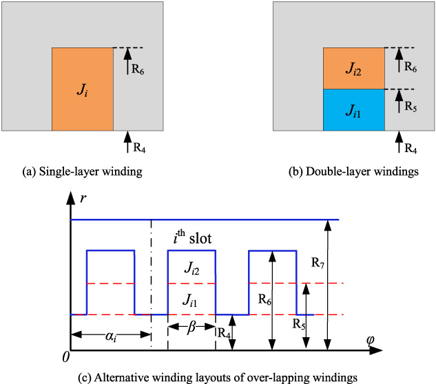
Winding configurations.
The tangential component of the vector magnetic potential at the stator slot boundary is zero because the magnetic permeability of the stator core is infinite. As a result, the following describes the boundary conditions of the vector magnetic potential at the bottom and sides of the stator groove.
The general solution of (9) is got by the separation variable method
Considering that the vector magnetic potential at the intersection of subdomains III and II is continuous, i.e.
The air-gap Laplace equation is given by
For subdomain II, (x
6 ≤ x ≤ x
5, 0 ≤ 𝜑 ≤ 2𝜋)
The generic solution of (15) is achieved by accounting for the periodic boundary condition and is represented as
The boundary condition of the vector potential in subdomain II is determined as
Subdomain I,
Subdomain III,
According to (17)
According to (18)
The Poisson equation is given by
For subdomain I,
The view of permanent magnets is shown in Fig. 3.
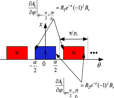
View of permanent magnets.

Surface permanent magnet magnetization orientation.
∙ Radial Magnetization
Two different magnetization orientations, including radial and parallel magnetization for each topology are shown in Fig. 4. For SPMVM, the radial and tangential components of the radial magnetization can be expressed as
∙ Parallel Magnetization
The radial and tangential components of parallel magnetization can be expressed as
The boundary condition is
The general solution of (23) is obtained by using the separation variable method
The boundary condition of the vector potential is
According to (33) can be determined
The magnetic flux density can be solved according to the vector magnetic potential of each subdomain
The calculation of the error about the air-gap magnetic density is as follows
To ensure the accuracy of the calculation results, the number of harmonics in each subdomain is finite. The maximum number of harmonics is n p _max for the permanent magnet. The maximum number of harmonics is n a _max for air-gap subdomain. The maximum number of harmonics is n s _max for the stator slot subdomain. The total number of harmonics is 2p r (2n p _max +1) + (2n a _max +1) + Z s (n s _max +1). According to the boundary conditions, the total number of equations to be solved is 2p r (2n p _max +1) + (2n a _max +1) + Z s (n s _max +1) for the original analytical method and the improved analytical method. Although both the traditional analytical method and the improved analytical method involve the same number of undetermined coefficients, the improved analytical method leverages integral symmetry to solve equations, whereas the traditional analytical method does not. Consequently, the number of coefficient equations to be solved in the improved analytical method is equivalent to half that of the traditional analytical method.
Electromagnetic torque
The Maxwell stress tensor method is used to determine the electromagnetic torque, which is represented by the following
For double-layer windings, the magnetic flux is
For the machine under investigation, the matrix connections between the stator slots and the layer-by-layer phase connections are provided by
For stator slots, the magnetic flux is.
The back-EMF of three phases is
The self-induction of three phases is
The mutual inductance of three phases is
Table 1 shows the geometrical parameters of the investigated machine. The three-dimensional structure of the SPMVM is shown in Fig. 5. As seen in Fig. 6, the magnetic field line and magnetic density distribution in 12s/20p SPMVM with radial magnetization are investigated by two analytical methods and FEM will validate the result.
Machine model parameters
Machine model parameters

SPMVM topology.

No-load magnetic flux distribution.
Here, we compare the results of the improved analytical method with those of the original analytical methods. The commercial finite element software establishes a 2-D model and calculates the magnetic field distribution. Figure 7 shows the calculation result of radial flux densities by the original and improved analytical methods located in the air-gap subdomain. The results are compared with those obtained by the FEM. The waveforms of the improved analytical method are closer to FEM than the original analytical method.
Figure 7(a) shows the no-load magnetic flux density of the radial air-gap. The results show that the improved analytical method and the FEM is suitable for the waveform coincidence. FEM is employed as the reference for calculating the error of air-gap magnetic density, as shown in Fig. 7(b). Compared with the original analytical method, the error distribution of the radial magnetic flux density obtained by the improved analytical method is more concentrated. Figure 7(c) show harmonics of the no-load radial magnetic flux density distribution in air-gap subdomain, which the 2nd, 10th, and 22nd harmonics components represent the modulation flux Bg1, the main flux Bg0, and the modulation flux Bg2, respectively. As shown in Table 2, the error of the 2nd harmonic amplitude by the original analytical method relative to FEM is 1.2%, and the error of the improved analytical method is 0.33%. The error of the 10th harmonic amplitude by the original analytical method relative to FEM is 2.12%, and the error of the improved analytical method is 1.42%. The error of the 22nd harmonic amplitude by the original analytical method relative to FEM is 5.71%, and the error of the improved analytical method is 5.77%. As can be observed, the improved analytical method is more accurate compared to the original analytical method for calculating the no-load air-gap magnetic field.

Magnetic density of the no-load air-gap.
The harmonic amplitude of magnetic field modulation and error
Figure 8 shows the electromagnetic torque for three methods at the rated speed. From Fig. 8, the resulting torque is closer to the FEM when using the improved analytical method compared to the original analytical method.

Torque waveform.
The variation of average torque to current is obtained from both the analytical methods and FEM in Fig. 9. It can be seen that the improved analytical method agrees better with the FEM result than the original analytical method.

Variation of the average torque with winding current.
The no-load back-EMF, with comparisons of calculated results by three methods at the rated speed of 500 rpm shown in Fig. 10(a), is well done and close to sine waves. It can be seen from the zoom part of Fig. 10(a) that the calculation result of the improved analytical method is closer to the FEM. The harmonics spectra of the back-EMF, as shown in Fig. 10(b). FEM is employed as the reference, and the relative error of the fundamental amplitude of two analytical methods is calculated. The relative error of the original analytical method is 1.71%, while the relative error of the improved analytical method is 0.034%.

No-load back-EMF and FFT result.
Figure 11 shows self-inductance and mutual inductance. As can be seen, the improved analytical model taking into account computational complexity gives good results compared to the FEM.
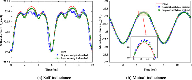
Inductance computations are compared.
In order to measure the stator core loss of SPMVMs, the loss coefficients of silicon steel sheets are often tested, and the experimentally determined loss coefficients are then substituted into the Bertotti core loss model to determine the stator core loss. The core loss of the prototypes in this paper is also tested using this technique. The model for calculating Bertotti core losses is
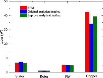
Losses.
As shown in Fig. 12, the stator core loss can be derived by substituting the loss coefficient into the core loss model. The loss is obtained from the 2D-FEM simulation results, and the results of the original analytical and improved methods are compared in Fig. 12, including a stator and rotor core losses, eddy current losses in PM, and copper losses. It can be seen that the calculation of the loss by the improved analytical method is closer to the FEM than the original analytical method.
The maximum harmonic orders of both analytical methods are taken as n p _max = n a _max = 200, n s _max = 20. Because of the weak symmetry of the PMVM, the original analytical method does not consider symmetry in the calculation, while the improved analytical method considers symmetry of the stator and rotor, respectively. Table 3 compares the solution times of the two analytical methods. It is evident that the number of equations solved by the improved analytical method is reduced by half, and the calculation time is reduced by 37.5% compared to the original analytical method.
The computational time of the subdomain method
The computational time of the subdomain method
To test the improved analytical method, a 12s/20p SPMVM with a high torque density feature is manufactured according to the parameter listed in Table 1.
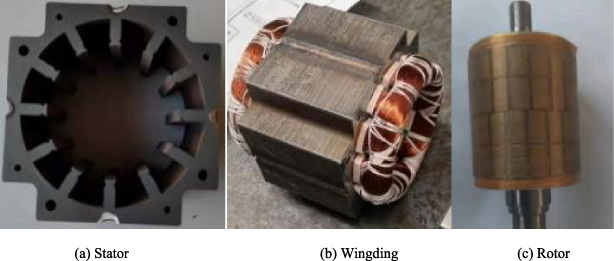
Prototype components.
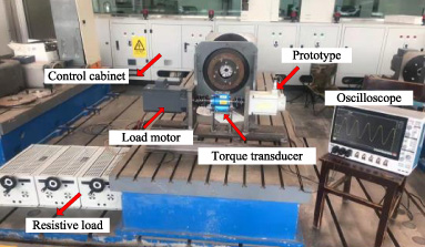
The test rig for the proposed SPMVM prototype.
The prototype and test bench structures are presented in Figs 13 and 14. The rated speed is 500 r/min with the rated power at 1 kW.
In Fig. 15, the no-load test is carried out at the rated speed of 500 rpm, to validate the back-EMF. As can be seen, the comparison results from the experiment, FEM, original analytical method, and improved analytical method are clearly in close agreement. The results show that the amplitude of the back-EMF of the experimental test prototype is about 3% lower than that predicted by the improved analytical method. The difference between FEM and the experimental results is within 5%. It mostly results from the improved analytical method, FEM, and the original analytical method’s assumption that the stator iron has infinite permeability, which neglects the magnetic reluctance in the stator yoke. Overall, the analytical method, the FEM and the back-EMF obtained by experimental tests are clearly in close agreement, further verifying the correctness of the above theory for the analysis of the back-EMF.
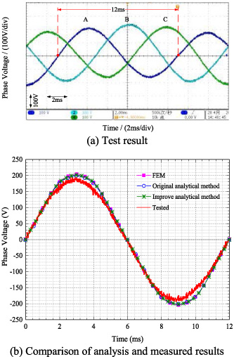
Phase voltage at 500 r/min.
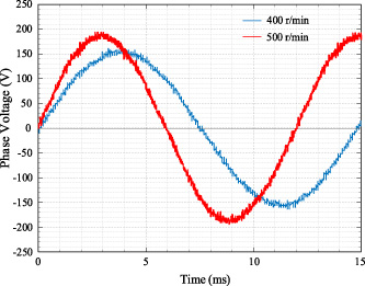
Comparison of back-EMF at different speeds.
In Fig. 16, the no-load back-EMF for different rotation speeds is depicted, which shows that with the decrease in speed, the back-EMF waveform distortions becomes more significant. When the speed is 500 rpm, the amplitude of back-EMF is 209 V and the corresponding distortion rate is 3.5%. At 400 rpm, the back-EMF amplitude and distortion rate is 156 V and 5.7% respectively. Of course the objective factors existed in the prototype manufacturing process cannot be ignored for positional specifications. Restricted by the manufacturing process conditions, the actual air-gap of the prototype is larger than the design value, resulting in higher non-linear magnetic leakage. Moreover, the stator teeth for field modulation are laminated with I-shaped punches, which can easily cause uneven air-gap.
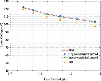
Voltage regulations under different resistor loads.
As illustrated in Fig. 17, the machine is driven by the load motor at the rated speed to evaluate the performance of voltage regulation under different resistive loads. In addition to internal resistance and leakage reactance factors, the motor armature reaction leads to demagnetizing flux, so the theoretical analysis and experimental test results of the output phase voltage decrease with the load current increase. Additionally, Fig. 17 shows that the results of the improved analytical method suggested in this paper are essentially in line with those of FEM and are closer to the measured results than the original method results. Therefore, the error analysis of the original analytical method, the improved analytical method, and the experimental data are carried out based on FEM.
As depicted in Fig. 18, the overall errors in the line voltage obtained using the improved analytical method are lower than those of other methods, with the maximum relative error being less than 0.5%. In contrast, the original analytical method exhibits a maximum relative error of 1.36%. The variance between the Finite Element Method (FEM) and the experimental results is 5.2%.
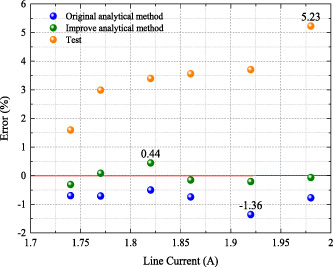
The error of line voltage relative to FEM.
In response to the challenges posed by a complex mathematical formulation, large coefficient matrices, and intricate computational procedures in the analytical subdomain model for a two-dimensional polar-coordinate electric motor magnetic field, this paper introduces an improved subdomain analytical model for the analysis of the magnetic field in surface-mounted permanent magnet Vernier motor (SPMVM). This model formulates the Laplace and Poisson equations for vector magnetic potentials in a quasi-Cartesian coordinate system within each subdomain. It utilizes the separation of variables method to derive general solutions for the Laplace or Poisson equations in each subdomain. Subsequently, these solutions are simplified into hyperbolic function forms, rendering the analytical expressions more straightforward than those in the two-dimensional polar-coordinate system.
By comparing this improved model with traditional analytical models, finite element models, and prototype experimental tests, several conclusions can be drawn. In contrast to the traditional electric motor magnetic field subdomain analytical model in the two-dimensional polar coordinate system, this model reduces the number of vector magnetic potential equations and simplifies the complexity of the original model’s coefficient matrices through coordinate transformation, resulting in shorter computational times. In comparison with traditional analytical models, finite element models, and prototype experimental test data, the no-load air gap magnetic flux, torque, and no-load back electromotive force exhibit consistent trends and reasonable agreement. Although some errors are present, they remain within the acceptable range defined by the design criteria, thus ensuring the accuracy of the original analytical calculations.
While finite element analysis offers numerous advantages in electric motor design, the analytical approach remains a rapid and convenient computational method for the initial optimization design and reverse validation of permanent magnet synchronous motors with weak symmetry.
Footnotes
Acknowledgement
This work was supported by the National Natural Science Foundation of China under grant 51967012, the Gansu Youth Science and Technology Fund under grant 22JR5RA807, the Incubation Program of Excellent Doctoral Dissertation-Lanzhou University of Technology, the Innovative Ability Enhancement Project of Gansu Provincial Higher Education under grant 2023A-199.