
Abstract
Machining technology plays a major role in modern manufacturing industries due to the growing demand for equipment and products for aerospace, automotive, precision machinery sectors etc. A key issue associated with any type of machining operation is the accelerated tool wear which leads to shorter tool life, thus to low machining precision and decreased productivity. In this paper an electromagnetic Non-Destructive Testing method (NDT), and in particular Eddy Current Testing (ECT), is used to detect the wear of used cutting tools vs a new one.
Introduction
The manufacturing industry uses cutting tools for plenty of processes such as drilling, milling, turning and boring. The cutting tools should have the appropriate cutting-edge geometry on the cutting edge and most importantly to retain these geometrical features during the manufacturing process in order to produce high quality products. Depending on the mechanical and physical properties of the workpiece, different drill-bits are used that vary in core material and coating [1]. Wear of the drill-bit tools constitutes a parameter affects to the final product quality. Moreover, it is a factor that cannot be avoided due to the drilling process itself. To protect cutting edges condition and consequently to extend the life of the tool, different types of cutting fluid are implemented during the machining process [2]. In addition, research results between an uncoated and a coated drill-bit, shows that the coated drill-bits have higher tool life than the uncoated drills. The coated drills reduce the torque and thrust forces at cutting edges [3]. Some techniques, for example using laser beam, implement to detect tools’ wear. There is a significant limitation of the current detection method. These traditional inspection methods are unable to accurately detect tool wear because they have ”blind spots” that cannot be effectively traced, often leading to inaccurate readings.
Most of the drill-bits are made by conductive materials. As a result, ECT can be used as NDT methods. The ECT method uses a coil, which is excited by an alternating electrical current. When the coil approaches a conductive material, currents are induced in the conductive material’s surface. The existence of a discontinuity in the sample leads to a change of the magnetic field that affects the impedance of the coil. The variation of coil impedance, and consequently the existence of discontinuity, depend on various factors as materials electrical conductivity and relative magnetic permeability, type of the defect, etc. [4,5]. The ECT method is a very sensitive method that reveals a negligible defect due to the eddy currents flow disturbance [6]. The drilling process progressively destroys the edge of the tool, thus, the eddy current flow changes.
Furthermore, the simulation of the ECT inspection using finite element method (FEM) extracts reliable results compered well to the experimental ones [7]. Simulation of such problems is applicable to both ferromagnetic and non-ferromagnetic materials, provided that the appropriate setup is used. Furthermore, the utilization of such tools is of great importance for the development of new probes and the advancement of the ECT method. Through simulation, key parameters such as test frequency and the geometrical characteristics of coils, as well as the distance between differential probe coils, can be precisely defined [8].
In this paper, the main idea is to record the signal from a brand-new machining tool before and after its use. The presence of a failure in the edges of the tool can produce a recognizable signal. The comparison of the results from the brand-new ones provides useful information for the drill-bit tools’ edge condition. Furthermore, during the drilling process small pieces of aluminum are stacked in the tool’s edge curvature. These aluminum chips affect the inspection by producing a signal due to their high electrical conductivity value. Apart from the experiment, a theoretical study carries out using finite element method and the comparison results for a brand-new drill-bit tool between simulation results and experimental ones are presented.
Experimental setup and results
For the experiment, a non-coated HSS drill-bot tool with 6.5 mm diameter is used. The nominal electrical conductivity is approximated at 1.1 MS/m, and the relative magnetic permeability is around 30. Moreover, the material in which the tool drills is an aluminum rod. The appropriate probe plays a critical role to the current implementation of the method. For the coils’ impedance measurement, a differential external probe is constructed according to the size of the used drill-bit. The subtraction of each coils signal produces better results. After the winding process the two coils’ inductance was measured to ensure the similarity of them. Both inductance measurement and the impedance changes are recorded by Agilent 4284a LCR Meter instrument. The two coils’ characteristics are shown in Table 1.
Differential coils’ characteristics
Differential coils’ characteristics
In order to avoid wobble during the scanning a constructed mount was used to stabilize the workpiece and a cylinder to allow only one axis of movement to the drill-bit (Fig. 1).

Constructed mount and the differential ECT probe.
The used testing frequency is a function of the sample material electrical properties and the depth in which the inspection reveals a defect. As the depth increases the eddy current density, and consequently the ECT detectability, decreases [9]. Moreover, the depth of penetration is inversely proportional to the square root of the test frequency. According to the need to inspect the surface of the tool, the used test frequency is 100 kHz to ensure the large current density on the tool surface. The scanning step is 0.5 mm, and the total scanning distance is 40 mm. The start distance between the tool and the probe is 1.5 mm. the movement of the probe achieved by a step motor in a XY-scanner.
The differential probe’s impedance changes results are a function of the drill times in an aluminum rod. Each drilling cycle corresponds to approximately a 10 mm drill length. Therefore, it is straightforward to determine the total length of the cut made by the drilling tool. Figure 2 shows the impedance signal variations as a function of the drill process.

Differential impedance changes as a function of drill times. (a) real component, (b) imaginary component, (c) impedance plane.
It is evident that damage to the tool’s edge generates a distinctive signal, which results from the drilling process. As the drilling length, indicating tool usage, increases, the damage at the edge generates a signal distinct from the reference signals. Additionally, upon observing Fig. 2, it becomes clear that alterations in the cutting edge’s geometry have a more pronounced impact on the imaginary component of the impedance. In the ECT method, a common evaluation practice involves analyzing the phase and amplitude of the signal [9]. Hence, as illustrated in Fig. 3, we can utilize these tools to evaluate the condition of cutting edges and predict the remaining useful life, essentially using them as acceptance criteria, provided that a record is maintained for a cutting tool until it is completely worn out.
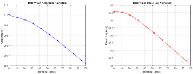
Drill-bit wear as a function of drilling process. Left: Signal amplitude. Right: Signal phase.
In order to understand and to compare the results of ECT measurements, an optical microscope with 5× lens used to capture the edge wear of the tool. Figure 4 shows the tool edge wear after 55 drill times.

Drill-bit edges in microscope with 5× lens.
The influence of the aluminum chips on the ECT signal presented in Fig. 6. It is obvious that the high conductivity of aluminum affects to the reactance of the coils due to the high eddy current density in chips surface. Moreover, this influence is not located in the start edge of the tool but in a small distance from it, as it is shown in the photo in Fig. 5. Thus, there is a need for a pre- ECT testing cleaning process in order to avoid aluminum chips signal affect.

Drill-bit with the stacked extra aluminum chips.

Differential impedance changes with and without chips. (a) real component, (b) imaginary component, (c) impedance plane.
The simulation of a drill-bit tool ECT inspection was made possible with a 3D model in the AC/DC module in COMSOL® Multiphysics v5.4 software. The workstation is an ASUS workstation with Intel® Core TM i7-7800X CPU at 3.50 GHz and 128 Gb RAM. The drill-bit domain imported as an STL file from a cad software and the rest of the domains designed in COMSOL (Fig. 7). The total number of elements is about 16.500 and the DoF ∼1.000.000. The computation time for each probes position is 35 sec.

Simulation Setup in COMSOL, Left: Drill-bit wear as domain. Right: Mesh.
This simulation is for a brand-new drill-bit tool. The comparison results concern the ability of COMSOL to extract reliable results for an ECT inspection in such geometries and materials. Moreover, the exact measurement of the tool wear and the simulation of this wear is very difficult due to the small size of the edge anomalies. Figure 8 presents the comparison results for the differential probe impedance changes.

Comparison results between simulation and experimental differential impedance changes. (a) real component, (b) imaginary component, (c) impedance plane.
The ECT method yields reliable results for assessing uncoated drill tool wear, primarily due to significant and repeatable changes in the probe’s differential impedance. Moreover, both signal phase and signal amplitude prove valuable for evaluating the tool edges’ condition, thereby assessing machining quality. Conversely, the drilling process generates chips/swarfs that can influence the coils’ impedance, particularly their reactance component, potentially affecting measurement accuracy. As such, a cleaning procedure is imperative prior to measurement to mitigate this influence. Furthermore, a typical ECT measurement can determine whether the tool requires further cleaning before inspection. It is advisable to record the signal from a brand-new drill tool as a reference for all subsequent measurements.
The simulation results indicate that the theoretical approach via numerical analysis aligns well with experimental data. Therefore, simulation holds promise as a valuable tool for future research, especially for probe development and optimizing the ECT method for non-destructive testing applications, particularly in drill tool wear inspection—an exemplary use case of this method.
In conclusion, there are numerous cases, including the measurement of wear in coated drill bits and milling tools, among others, that comprise a research area for the application of ECT as an inspection method. Both experiments and simulations will be conducted to investigate the detectability and efficiency of the ECT method for measuring tool wear, with the goal of reducing the impact of tool failure on the final product’s quality.