
Abstract
This paper presents a portable device based on an Anisotropic Magnetoresistance (AMR) sensor for Steel Health Monitoring. The system operates by detecting magnetic anomalies in ferromagnetic materials caused by strain, corrosion, etc. This sensor can have various applications in the transportation, building, and aerospace fields for safety and maintenance monitoring of ferromagnetic materials. In this work, a low-cost device, that combines a high-sensitivity AMR sensor, a microcontroller, and supporting electronics has been designed and implemented. This sensor allows the contactless measurement of the magnetic flux density along three axes, when placed above the material under test, while the microcontroller and the required electronics enable real-time analysis and monitoring of measurements. In order to house and protect the sensor under various circumstances, a 3D-printed enclosure has also been created. This device can be used along with rehabilitation techniques for treatment of defective areas of an under-test material. Its versatility allows it to be employed in a variety of testing conditions for both single-point and scanning mode monitoring. The device’s portability, ease of use and applicability to on-site measurements make it accessible to a wide range of users, requiring only a personal computer to display the measurements. Finally, measurements are presented to prove the device’s accuracy for steel health monitoring.
Keywords
Introduction
Steel is used as a fundamental material in various applications, due to its exceptional mechanical properties. It is widely used in sectors such as transportation, energy, and industry. Thus, it is crucial to use steel health monitoring techniques, to inspect and monitor the condition of steel, in order to prevent structural failures [1]. Those failures may have the form of cracking and deformation caused by the existence of residual stresses on the material. So, monitoring these residual stresses is also very important for steel evaluation [2,3].
According to the measurement principle, non-destructive and destructive methods can be used to measure the residual stresses of a material. The first category includes the methods of X-ray diffraction (XRD), Neutron diffraction (ND), Ultrasonics and Magnetics [4]. In the case of XRD there are some restrictions that must be considered during the measurement such as constant temperature, the sample’s shape and coating and the preparation of the material [5]. ND is used to investigate the crystal structure and phase composition of materials like steels, but the access to the required instrumentation for this method may be limited, expensive and time-consuming [6]. Ultrasonic method for NDT is based on the laws of acoustoelastic theory, which states that the velocity of elastic wave propagation depends on mechanical stress. For this technique there are sample preparation requirements and also the penetration depth is limited [7]. According to the elastic mechanics principles, the residual stress state can be determined by measuring the area’s strain or displacement. So, another destructive method is the use of sensors for strain gauge measurements. This technique except from the fact that causes permanent damage to the material, the method is also relatively unsuitable for low-level residual stress measurements, as the sensitivity of the release strain is lower than that of other mechanical methods.
Each of the above-mentioned techniques has several drawbacks, mostly related to the sample preparation, the cost of the measurement instrumentation, the limited sensitivity and the requirement for laboratory conditions [8,9]. However, the use of non-destructive testing techniques by portable devices for fast and accurate on-field measurements, is required in many applications. The device presented in this work is based on the use of an anisotropic magnetoresistance (AMR) sensor, that can measure changes of the surface magnetic permeability of the materials under test, indicating possible defects. The developed device, as well as indicative measurements, are presented in the following sections.
Principle and design
The developed device utilizes an AMR sensor for measuring variations of the magnetic flux density, correlated with the magnetic flux leakage due to defects or changes of the magnetic permeability of the material under test in general [10]. Anisotropic Magnetoresistance is based on the change of the electrical resistance of a material in response to an external magnetic field. The effect depends on the relative orientation of the material’s magnetic domains and the direction of the applied magnetic field. This sensing element is composed of ferromagnetic thin film resistive strips, manufactured on silicon wafers. The output voltage changes according to the direction of the field. Thus, the AMR sensor is thought to be suitable for magnetic field measurements and thus for health monitoring of ferromagnetic materials.
One of the main goals of this work is to develop an accurate, portable, and ease-to-use device for Steel Health Monitoring. For this purpose, a 3D AMR sensor LSM303DLHC (STMicroelectronics, Geneva, Switzerland) has been used as a sensing element for measuring the magnetic flux density of the ferromagnetic samples, having a sensitivity of 1100 LSB/gauss [11]. It can be supplied by either 3.3 V or 5 V, and it also supports 16-bit data output and the I2C serial interface. So, it can be easily connected to a microcontroller, in order to collect all the measured data about the magnetic field and transfer them to a PC. Additionally, it can monitor the magnetic field on 3 axes, leading to more accurate measurements and also providing the ability to scan the material in three dimensions and correlate the data with the residual stresses of the surface of the material.
Microcontrollers are considered to be the best choice for analyzing and visualizing the signal of such a sensor, due to their low cost comparing to their capabilities, as well as their connectivity features, offering USB connectivity and support for several communication protocols. For this work, the ESP32 microcontroller (Espressif Systems, China) in the form of a development board was found appropriate, including an Xtensa dual-core 32-bit LX6 processor with an operating frequency of up to 240 MHz, integrating a rich set of peripherals and protocols, a 12-bit analog-to-digital converter (ADC), USB port and plenty of analog and digital pins. This microcontroller is connected to the AMR sensor through the I22C protocol, and the 3 digital values received, correspond to the magnetic field for the 3 axes, in μT.
The integration of the electronics of this device is presented in Fig. 1a, where the AMR sensor is placed perpendicularly to the ESP32 board. These components are placed on a custom 30 mm × 80 mm board that was designed and manufactured for this purpose. Finally, a 3D-printed enclosure was designed and manufactured to house and protect the electronics. By this way, the AMR sensor is placed in a specific position, providing repeatability in the measurements. Figure 1b shows the developed portable device, which is easy-to-use by just plugging it in a PC using the USB connectivity.

(a) AMR device. (b) Complete device with the 3D printed enclosure.
The developed device is capable of detecting anomalies on defected areas of a steel sample by scanning it. In order to validate the use of the proposed device, indicative measurements were held. This testing procedure included scanning in both directions sequentially, electrical steel sheets (300 × 34 × 0.6 mm3) with different defects. The scanning procedure was held with the device above the sample at a distance of about 1 mm, along the direction of the x-axis. In order to better determine the output values along the sample under test, the measurement was started and ended 100 mm before and after the sample’s length, respectively. By this arrangement, the magnetic flux density output values of the AMR sensor were observed in each sheet. Then, the defected area of each sample was correlated with the changes in the measured magnetic flux density. So, the output of the device can be indicative of failures on steel samples at specific spots. It should be noted that, in order to cope with the effect of the earth’s magnetic field, as well as the different magnetic properties of each sample under test, the result assessment was focused on the variations of the output signal instead of the magnetic field’s value.
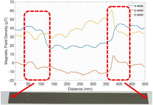
Measurement of a steel sheet with no visual defects, using the developed device. The locations of the edges of the sample are depicted with the red rectangles.
The outputs of the developed device, monitoring the health of a steel sample without visual defects and a steel sample with 2 defected areas, are presented on Fig. 2 and Fig. 3, respectively, indicating a Signal-to-Noise Ratio of about 24 dB. The vertical axis of each figure corresponds to the magnetic flux density in μT, while the horizontal axis corresponds to the distance travelled by the sensor. As mentioned above, the range 100 mm to 400 mm of each figure corresponds to the actual sample’s length. More specifically, Fig. 2 shows the measured magnetic flux density (on the three axes) of an electrical steel sample without any visual defect. As it can be observed, there is no significant change on the output of the magnetic sensor, except from a variation of the signal corresponding to the two edges of the sample (magnetic edge effect).
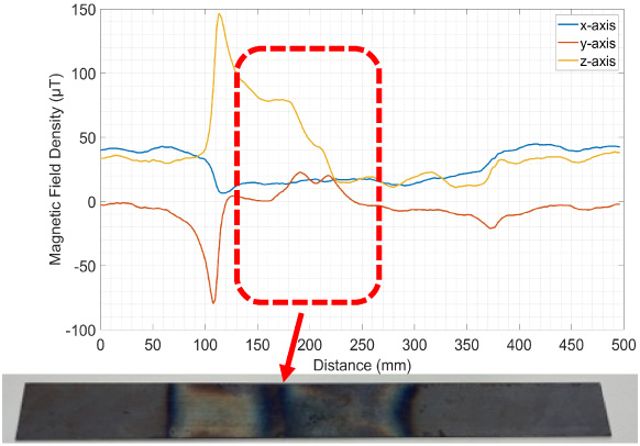
Measurement of a steel sheet with visual defects, using the developed device. The defected area is depicted with a red rectangle.
Figure 3 presents the measured magnetic flux density of an electrical steel sample, which was subjected to induction heating and rapid cooling at two areas along its length, prior to the measurement, in order to modify its magnetic properties. The changes of the observed AMR sensor’s output signal correspond exactly to the heat affected areas of the steel under test, indicating that the device can accurately detect potentially defected areas, through their different surface magnetic permeability values. Additionally, two more fluctuations of the magnetic flux density can be observed, which represent the edges of the sample, as previously mentioned.
Figure 4 presents a comparison between the signals of the AMR sensor in 3 axes, while scanning the two above mentioned steel samples. The solid lines correspond to the measurements of the sample without visual defects, while the dashed lines correspond to the defected sample. As it can be observed, the signals of the non-defective sample, does not show significant variations along its length. On the contrary, the second sample’s signals present fluctuations that correspond to the areas of the imperfections.

Comparison between the measurements of the sample without defects (solid lines) and the sample with defects (dashed lines). The defected area of the second sample is depicted with a red rectangle.
In this work, a complete device for inspecting the health of ferromagnetic materials like steel, has been developed. It is based on the detection of changes in magnetic properties of the materials under test, by monitoring their magnetic flux density after scanning their surface. The device, consisting of an AMR sensor, a microcontroller and a suitable enclosure, is able to detect defects on the surface of steel samples, as it was shown by the preliminary measurements. These measurements are proven very important for the lifespan estimation of many steel structures. Specifically, after determining the location of the defective spots of steel, stress rehabilitation methods can be used to treat them locally. The great advantage of this method in comparison with other destructive and non-destructive techniques, is the fact that there is no need for special preparation for the sample prior to the measurement. Moreover, this device can be used for on-site measurements as it is portable and easily connected to a PC via a USB cable, while no heavy or special equipment is required. As a result, its high sensitivity, combined with its low cost, make the proposed device suitable for a wide range of non-destructive testing applications.
Future work includes the development of a measuring arrangement that can be used to scan the surface of the materials under test, while ensuring the repeatability of the measurements. To achieve this, the arrangement must provide continuous and known velocity and lift-off distance from the sample, while it moves the device above the surface of the materials. Additionally, the performance and accuracy of the device must be tested using more and different kinds of ferromagnetic samples that will be tested for both laboratory and on-field applications.
Footnotes
Acknowledgements
This research has been co-financed by the European Regional Development Fund of the European Union and Greek national funds through the Operational Program Competitiveness, Entrepreneurship and Innovation, under the call RESEARCH – CREATE – INNOVATE (project code: T2EDK-02521).