
Abstract
As a new type of braking method, the eddy current brake (ECB) is nowadays widely applied in life and military. The ECB can generate the strong resistance by the magnetic field, and obtaining the accurate magnetic induction distribution is essential in the ECB modeling. This paper proposes an analytical model of a cylinder ECB used in the artillery that operates under the intense impact load. This model takes the axial edge effects into consideration in both static and dynamic conditions. Firstly, this paper introduces the structure and working principle of this ECB. Secondly, a multilayer theory with virtual region is proposed to calculate the magnetic induction distribution considering the end effect. Thirdly, Finite Element Method (FEM) model is established to describe the spatial variation of the magnetic field in different conditions. Finally, the analytical model is compared with the FEM model to prove its validity and predict the working characteristic of the ECB under the intense impact load, the max recoil displacement and speed range both meet design and work requirements.
Introduction
Eddy current brake (ECB) is an electromagnetic device. When a magnet is moving paralleled inside a conductor cylinder, eddy current will be generated in the conductor, which will form a new magnetic field and electromagnetic force to prevent the magnet from passing through [1]. The magnitude of this force depends on the magnetic flux density in the conductor and the relative speed between the magnet and conductor.
Compared with the traditional brake, ECB has many advantages, such as being non-liquid, friction-free, no noise, relatively inexpensive, free of pollution, high reliability, long lifetime, and so on. ECB can be divided into three types according to its structure, which is linear, axial unipolar and planer. They are widely used in life and industrial fields. For example, the linear ECB was used as a supplement for mechanical brakes in high speed maglev trains to help prevent accidents at high speeds [2,3], the axial unipolar ECB was applied to the brake of electronic vehicles and heavy trucks to maintain vehicle speed and ensure driving safety [4–7], a pendulum-type EC-TMDs based on the planar ECB was applied as a countermeasure to increase effective damping to mitigate wind-induced vibrations of civil structures [8,9], and so on [10,11].
There are many analysis and research of ECB and similar electromagnetic device can be found in literature. Chen et al. [12] used the subdomain method to derive the analytical model of ECB braking force considering the skin effect of the disc-shaped conductor. They analyzed the characteristics of critical speed and maximum braking force in a 2D Cartesian coordinate system, but ignored the end effect of the ECB. Kou et al. [13] presented a novel cage-secondary permanent magnet (PM) linear eddy current brake with wide speed range. They proposed a new analytical model in conjunction with multilayer theory, which considered the saturation and final effects of secondary iron teeth, and also in a 2D Cartesian coordinate system. Jin et al. [14] established an analytical model of a permanent magnet linear ECB considering edge effects and verified it by comparing with 3D FEM model. In this model, the braking force was calculated considering the dynamic transverse edge effect through conformal mapping method, but ignoring the lengthwise edge effect. Lu et al. [15] proposed an effective analytical model of a permanent magnet linear synchronous machine, which considered the end effect and the slotting effect by adding virtual slots and adopting relative air-gap permeability respectively. But they only considered the end effect in static condition and the model cannot be used in dynamic condition. Similar research of ECB and related equipment have been established in other work [16–23].
The cylinder ECB principle has been recently studied for application in the artillery recoil device to reduce the recoil force and improve shooting stability. Li et al. [24] investigated the damping and demagnetization effect of the ECB under impact load. They measured the recoil displacement and the eddy current density in the inner tube and verified the FEM model. But they mostly focused on the experiment with the physical meaning of the research neglected. Li et al. [25] investigated the effect of temperature on the magnetic field and recoil displacement. Li et al. [26–28] established the analysis model using subdomain model and magnetic equivalent circuit, and then calculated the partial magnetic field distribution of this ECB. They assumed the period of the magnetic flux density distribution was the same as the permanent magnet layout, this assumption ignored the outer half of the PM blocks in both end and the accuracy was reduced.
The analytical model, with clear physical meaning and low computing resource requirements, plays an essential role in the preliminary design of ECB [29]. Another advantage is that it does not have the process of structural modeling and meshing, which spend a lot of time, and does not need to consider convergence issues. It can calculate fast and accurately within a few minutes. So far, there is no prior work that analytically calculates the magnetic induce intensity and the eddy current distribution in the ECB while considering the axial end effect in static and dynamic condition under the intense impact load.
For further research, an analytical model of the PM cylinder linear eddy current brake is established in this paper. The rest of the article is organized as follows. In Section 2, the structure and working condition of this ECB was introduced. In Section 3, by adding virtual PM, a multilayers analytical model considering the axial end effect was established, the derivation process of physics and mathematics was explained in detail. In Section 4, the FEM model was established to analyze the spatial variation of the magnetic field in different areas and condition. In Section 5, the results of the analytical model were compared with the FEM model to verify its accuracy and effectiveness, then the working characteristic of the ECB on the artillery was analyzed.
Structure of PM eddy current recoil brake
As shown in Fig. 1, the components of this ECB can be roughly divided into barrel, permanent magnet, inner tube and outer tube. When the artillery is fired, the barrel goes backward with the permanent magnet array at high speed, and the inner tube generates strong eddy current to resist the change of magnetic flux. The magnetic field generated by the eddy current will counteract the applied magnetic field and braking force will be generated. The outer tube mainly acts as a magnetic shield to constrained magnetic field. When the max recoil distance is reached, the recoil part will be reset by the recuperator and then ready for the next launch.

Structure of the ECB.
Virtual PM Region
Figure 2 shows the analytical model of the ECB with virtual PM in 2-D cylindrical coordinates. The main parameters are the PM array length l
p
, the PM height h
p
, the air gap thickness h
g
, the inner tube thickness h
c
, the width of PM with radial magnetization l
m1, the width of PM with axial magnetization l
m2. Due to the length difference between the PM and inner tube, the interface condition between them and constitutive relation is aperiodic. So this paper used the virtual PM region to consider the end effect. By adding two virtual on the both side of the PM, the periodic interface conditions are imposed. The equal relation is obtained as

Analytical model of ECB.
According to the radial layered structure of the cylinder linear eddy current brake, it can be traditionally divided into internal air, barrel, PM, air gap, inner tube, outer tube, outside air, and so on. But too many regions will waste computing resources and do not improve the calculation accuracy obviously, especially when consider the end effect. To analyze the magnetic field of the cylinder linear ECB and simplify the calculation, this paper simplified the seven regions into four regions without affecting the accuracy much. Some area can be ignored and reflected in the form of boundary conditions. Because the H field in outer tube is not big enough, the influence of saturation doesnt need to be fully considered in order to calculate faster. So the material of outer tube is assumed to be perfect magnetic conductor, and the permeability of it is infinite.
Because the model is 2D cylindrical coordinate, the magnetic vector potential only has the circumferential component. It is set as dependent variable potential to deal with the governing equations based on the Maxwell equations.
Under quasi-static conditions, electromagnetic fields enter the conductor in the form of diffusion. When the frequency is high, it will produce a skin effect. In this model, the frequency of electromagnetic field is depended on the speed of PM. It is very slow relatively and the free electron can respond in a timely manner. So the skin effect is not obvious and can be ignored reasonably.
And the scalar form is
In the Halbach array, the

Waveforms of the PM normal magnetization.
In order to calculate conveniently,
In this 2D cylindrical coordinates, magnetization only have the z and r component and the derivative in the r-direction is zero, so
In dynamic case, due to the relative motion of the coordinate system, there will form an electric field as Eq. (11) according to the Faraday’s law of electromagnetic induction.
This will generate eddy current and the governing equation is shown as Eq. (12) (assuming the direction of
To solve this problem, this paper reasonably assume that A has the period of T as shown in Fig. 2, and it can be described in the form of Fourier Series as
In this way, it can simplify the complex partial differential equation into ordinary differential equation. The governing equation of Fourier coefficient in different region is shown as Eq. (14). The difference between static and dynamic condition is the whether there is a source item in region4 (A 4n ).
Dynamic condition is an important condition when the ECB is working, though there is no braking force in static condition, it still can be used to verify the accurate of this model and compared with the experiment data easily.
The general solution of each ordinary differential equation is
The coefficients C and D can be derived by the form of Maxwell’s Equations at the interface and the boundary condition. This means eight equations are needed to solve the equation system. There are two equations in each interface condition and one equation in each boundary condition.
Eddy current loss
The current density generated in the inner tube can be calculation as
And the eddy current loss can be calculated by the differential form of Ohm’s Law
The magnitude of the braking force is equal to the Lorentz force generated by the relative movement of the PM and inner tube, but they are opposite, it can be calculated as:
This ECB is applied to the artillery recoil device. The recoil displacement is an important target parameter. When the ECB is working, the huge resultant force in bore and the force of the recuperator is acting on it. The resultant force in bore changes with time and the force of the recuperator changes with the displacement, their relationship is as follows
Difference method is used to solve this equation, the variable parameters a i and v i are considered to be constant during Δt. The process is shown in Fig. 4.
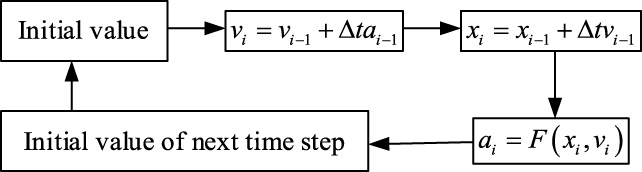
Calculation flowchart.
To better research the end effect, the FEM model is established. The two-dimensional finite element mesh is show in Fig. 5, the air gap and inner tube is narrow, so the element size is extra small. Figure 5 shows the norm of magnetic flux density and the contour line. The expression of contour line is Eq. (25). As shown, the tangent direction of each point on the contour line is as same as the direction of the magnetic induction. This means the contour line is just the magnetic induction line.
Figure 6(a) is the static state, and the distribution of the magnetic induction line is regular. Figure 6(b) is the dynamic state, the magnetic induction line is mixed because the eddy current is generated in the inner tube. The current will also induce magnetic field to resist the external magnetic field changing the internal magnetic field. The magnetic field in the inner tube tends to remain constant while the PM is moving, so the magnetic induction line changing lags behind the mover.
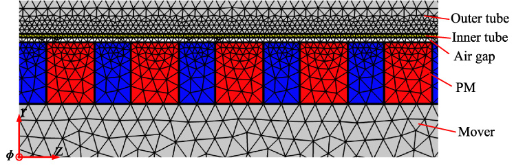
Finite element mesh generation.

Magnetic field distribution in the middle. (a) Static state. (b) Dynamic state (8 m/s).

Magnetic field distribution in the end at 8 m/s. (a) Right side. (b) Left side.
Figure 7 shows the distribution of the magnetic field in the end of the PM in dynamic state. The magnetic field in the end is weaker than the middle, so the contour should be dense to show the end effect. The magnetic induction is decreasing in the end. Due to the eddy current in the inner tube, the magnetic induction on the right side is different from it on the left side. The contour line on the left is sparser than the right, so the magnetic induction should be weaker than the right side.
To verify the accuracy and effectiveness of this analysis model, the result was compared with the FEM model. The magnetic field of the eddy current brake was calculated. When calculating the magnetic field and eddy current density, this paper reduced the number of the PM pair in order to show the distribution in the end of the PM array obviously, the distribution in the middle is the same within each period. Both static and dynamic situations are calculated. The analytical result and the FEM result can be seen obviously consistent.
Parameters of ECB used in the calculation
Parameters of ECB used in the calculation
Air gap
The radial magnetic flux density in the air gap was calculated, as shown in Fig. 8. The magnetic flux density distribution is symmetrical in a static state. The flux density at the end is lower than in the middle and gradually disappear. However, when in dynamic state, the eddy current is generated and significantly affect the magnetic field. In the middle of the ECB, because the direction of the eddy current is all circumferential, it enhances the radial flux density on the side of the motion direction and reduce it on the other side. The current plays a role in both magnetization and demagnetization. Ultimately, the eddy current enhances the radial flux density on the right and reduces it on the left.
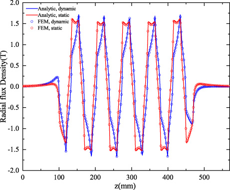
Radial magnetic flux density in static and dynamic state.
Figure 9 shows the difference between traditional method and proposed method. The result is obviously different from two methods. The flux density immediately reduces to zero without considering end effect which is not correct physically.
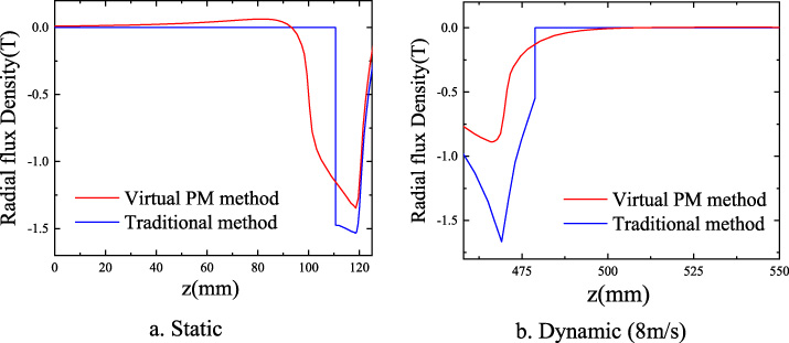
Comparison with traditional and proposed method.
As shown in Fig. 10, the axial magnetic flux density in the air gap was also calculated. In static state, it repeatedly increases and decreases due to the special arrangement. In dynamic state, the axial flux density is greatly enhanced. The permanent magnet array is moving fast, and the eddy current will prevent the magnetic field from changing in the inner tube, and the magnetic field should be continuously distributed so the magnetic induction line will extend in the z-direction, and the axial flux density will be significantly increased. It is not a good thing because the axial magnetic flux cannot generate effective braking force.

Axial magnetic flux density in static and dynamic state.
The current density distribution was calculated. As shown in Fig. 11, the analytical result and the FEM result are totally consistent. The current density is periodically distributed in the middle of the ECB, but at the end of the ECB, the density decreases because of the magnetic flux leakage. The peak value of the current density increases as the relative speed increases when the speed is low. It means the faster speed will generate greater current and more eddy current loss.

Current density under different speeds.
The braking force characteristic and the eddy current loss were calculated, as shown in Fig. 12. It can be seen that the analytical result is consistent with the FEM result. When the speed is under 15 m/s, the braking force increases with the speed increasing but getting decreasing while the velocity is larger because of the eddy current demagnetization. The faster the speed of PM, the higher the frequency of change of the magnetic field, the generated electric field will be stronger according to Faraday’s law, so the more current generated. But the magnetic field generated by current, called current demagnetization field(CDF), always weaken the original magnetic field of PM. When the speed is low, so the CDF is very weak, so the braking force increasing with the speed. But when the speed is high, the CDF will produce sufficient influence on the original magnetic field, so the braking force will not continue to increase with speed. So the ECB has a great performance at low speed when the speed is about 15m/s. With the eddy current loss continuously increasing, it will generate lots of heat, and high temperature will reduce the conductivity and magnetic permeability of materials and affect the performance of ECB.

Braking force and eddy current loss of ECB.
Max recoil displacement is an important target of this ECB, the recoil distance is limited in the design of the artillery recoil device. Excessive displacement will make it difficult to lighten the artillery. According to structural design requirements, the recoil distance should be less than one meter. This model can be used to predict the recoil displacement and velocity when the artillery of 155 mm caliber is working. The resultant force in bore depends on the charge weight, the different number means the different charge weight, the curves of this force are shown as Fig. 13.

Curves of resultant force in bore (F p ).
The recuperator is a hydropneumatic recuperator which is widely used in large caliber artillery [30]. The gas is used as the energy storage medium and the role of liquid is transmitting force and sealing gas. When it works, due to the movement of the piston, the gas in the recuperator is compressed, and the gas exerts force on the piston through the action of the liquid, which is F f in Eq. (24). So the force of the recuperator is related to the displacement, as shown in Fig. 14.

Curve of recuperator force (F f ).
The recoil displacement is calculated by the analytical model and compared with the FEM model, which uses moving mesh method. As shown in Fig. 15, the curves are roughly the same. Because this model assumes that the outer tube is perfect magnetic conductor and the relative permeability is infinite, and the convergence of moving mesh is poor, the results have some small errors. With the increase of the charge weight, the displacement is also increasing. When reaching the max charge weight, the max displacement is about 936 mm and meet design requirements.

Curves of recoil displacement.
The recoil velocity is shown as Fig. 16 and maximum value is shown in Table 2, the velocity is increasing with the charge weight. When the charge zone is full, the max velocity is about 13 m/s. Refer to Fig. 11, if the velocity is under 15 m/s, the braking force increases fast with the velocity and the eddy current loss generated is relatively low. It is an appropriate working range for this ECB, so it will bring out the full potentials in this condition.

Curves of recoil velocity.
Max recoil displacement and velocity
In this paper, an analytical model of PM cylinder linear eddy current brake was proposed. By adding two virtual PM region, this paper took the end effect into consideration and calculated the whole magnetic field accurately in both static and dynamic conditions, the braking force and eddy current loss was also calculated. A FEM model of this ECB was established to describe spatial distribution visually and verify the accuracy and effectiveness of the proposed model. The analytical and numerical results were in good agreement. Finally, the max braking displacement and velocity were calculated, the results showed that the max working displacement is less than one meter and the max velocity is under 15m/s under the intense impact load, which meets the design and work requirements. It can provide guidance for its design and experiment.
Through analytical model, the proposed method can be calculated fast. However, it may also have some disadvantages. If the number of PM is too large, the Fourier transform requires more terms to ensure its accuracy, it may consume a lot more of computing resources. For efficient calculation, the electromagnetic field should be calculated separately in the middle and the end in that situation.