
Abstract
In this article, a magnetic shield for automotive Wireless Power Transfer (WPT) systems is proposed. Its innovative feature consists in the positioning of the shield, that is part of the Ground Assembly (GA) of the WPT system. Passive coils, assembled in an array-like structure to build the shields properly located near the transmitting coils are investigated. Currently, there are a variety of shielding methods, each of them with its peculiar feature. The proposed method is simple and does not increase the transmitting and the receiving coil sizes, a constraint that is often critical from a practical and an economical point of view. The main characteristic of the proposed shielding method is the location of the shielding coils on the same level as the GA. The results here presented are validated by Finite Element (FE) based simulations and are referred to an experimental prototype of wireless charging systems for electric vehicles operating at 85 kHz with a transmitted nominal power of 3.3 kW. The results show that the proposed shield reduces the leakage magnetic flux density in the system up to 37% with a marginal impact on the transmission efficiency, complying the SAE J2954 international standard.
Introduction
Electric Vehicles (EV) are becoming increasingly popular in people’s daily lives [1,2] and wireless power transfer (WPT) is now a viable technology, characterized by well-known advantages if compared to the more common conductive charging. In this paper, we consider the Magnetic Field (MF) shielding problem relative to the dynamic charging of EV because of its potential impact on the daily human activities in the proximity of these systems. The working principle of resonant non-radiating WPT systems lays on the magnetic coupling between transmitter and receiver without a closed ferromagnetic core. The magnetic flux density, responsible for the power transfer, is not completely confined between the coils, and can affect the behavior of nearby equipment and/or being harmful for human beings. The magnetic flux density outside the active zones is often referred to as Magnetic Flux Leakage (MFL), and the most common techniques to reduce it is by using conductive shields and ferromagnetic bars/tiles. In an EV under charge, the driver is above the receiving coil, which is usually shielded by ferrite tiles and aluminum plates, in a relatively safe area. Nevertheless, since people can be close to the sides of the vehicle, on either side of the transmitter and receiver coils, shielding must be introduced also considering that these areas are close to the missing part of the transformer core. In [3], the authors summarize recent standardization activities related to human exposure to electromagnetic fields (EMF) and evaluate the safety of magnetic systems and environmental EMF in human daily life.
Nowadays, a great amount of literature is dedicated to the study and the design of new shielding strategies, and resonant coil shielding is among the most widely used shielding methods because, if properly designed, it can be an efficient strategy and doesn’t need an external power supply. Such a system has to be properly designed since the additional resonant coils produce modifications to the system’s characteristics, in particular to the field distribution, and their effect should interfere as less as possible with the normal operation of the device.
The shielding coil can be used to efficiently decrease the MFL strength at a specific frequency, when the resonant shielding coil is tuned at the main WPT system frequency [4,5]. In [6] a passive shielding structure is developed for a 7 kW wireless charging system for electric vehicle applications, with the goal of reducing shielding losses and MFL. An improved hybrid shielding construction is presented in [7] to reduce the MFL in the external area of the coils by surrounding them with a ring-shaped aluminum plate. In [8], a suitable resonant frequency value of the shielding coil is designed to achieve a low level of electromagnetic interference at a specific nth harmonic frequency in the WPT-EV system and higher power transfer efficiency values. The electric and magnetic field strength produced by WPT systems varies in terms of frequency bands and power levels according to different regulations: a discussion on this limit in WPT systems is shown in [9], while [10] and [11] analyze more in detail the case of WPT for EVs. In [12] the authors presented a novel coil architecture for dynamic WPT systems, characterized by interoperability and increased robustness to misalignment; however, the leakage field shielding is achieved by the use of a usual conductive shield.
At this stage, it is important to underline that besides shielding, Foreign Object Detection (FOD) methods are often implemented into WPT systems. Based on the type of detected objects, FOD can be divided into metal object detection (MOD) and living object detection (LOD). In [13] a review of different approaches is presented; however, FOD itself cannot be considered as an alternative to proper shielding. In this specific WPT system, the space on the side of the coils (the area where we want to reduce MFL) cannot be considered an area with limited accessibility, because it is where at least the driver must be present in order to access the vehicle. In addition, in quasi-dynamic WPT also pedestrians can find themselves close by the coil assembly.
Electric vehicle wireless charging model.
In this paper, a resonant coil matrix used as electromagnetic shield is investigated, first considering a passive implementation. In order to evaluate the MFL distribution and strength, the authors implemented an FE model that was solved by a commercial software, followed by a heuristic procedure based on the physical understanding of the phenomenon. The main goal of the design is to achieve a good magnetic field shielding in a specific volume around the active coils without significantly impacting the effectiveness of the wireless power transmission. In order to consider meaningful magnetic field values, the Society of Automotive Engineers (SAE) standard has been followed: the design objectives are met by if the strength of the flux density is in the range below 27 μT. Finally, the proposed shielding coil for a wireless power transmission system of 3.3 kW at 85 kHz has been specifically based on an existing prototype.
The characteristics of the coils’ leakage field and the features of the MF are examined in Section 2. An equivalent lumped circuit model is described in Section 3. A shield design and verification are suggested in Section 4, along with its corresponding electric and geometric limitations. The final conclusions are shown in Section 5.
Wireless power transfer system
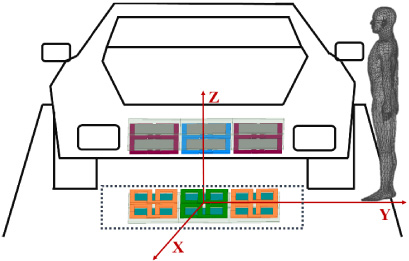
The most common configuration of an EV WPT system consists of transmitting and receiving coils, ferrite bars, and aluminum conductive shield, which are symmetrically placed on both sides (see for instance Fig. 1). The coils are respectively placed under the ground and below the chassis of the electric vehicle. The shielding system analysed in this study has been designed starting from a WPT prototype built in the laboratory; the working frequency is f = 85 kHz, the rated current is around I M = 56 A; a circular cross-section Litz-wire with diameter of d = 6.5 mm (2500 strands with diameter d i = 0.1 mm) has been used for the coils construction [14].
Since the main objective of this study is the MLF, the complex geometries of the Litz-wire and of the coils have been simplified to make reasonable use of computer resources. The homogenization of the active conductors is here performed in the simplest possible way, i.e., considering a homogenous conductor carrying the total current with uniform current density distribution in the whole cross-section. In addition with the same rationale in mind, a further simplification has been performed: since both the GA and the Vehicle Assembly (VA) consist in a “double D” composed by N conductors, the model used to evaluate the shielding performances contains a single conductor carrying the total current I T = NI M = 10I M , as shown in Figs 2(a) and 2(b).
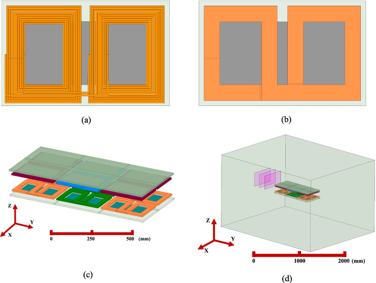
Wireless power transfer for EV. (a) TX Coil; (b) simplified TX Coil; (c) simplified TX and RX Coils; (d) the WPT system with test planes.
The system described in [12] is shown in Figs 2(c) and 2(d); it includes ferrite bars used as flux tubes and conductive plates to shield the magnetic field behind them; however, along the perimeter of the WPT system, the MFL can reach relatively high values, which, for example, could be potentially dangerous for pedestrians. The sides where this is more likely to happen are those parallel to the motion direction (i.e., the x-axis). Figure 2(d) also shows three test planes where MFL is expected to assume high values and where the proposed shield is designed to produce its shielding effect (further details are given in the remaining part of the paper). The main design parameters of the system are reported in Fig. 3 and described in Table 1.
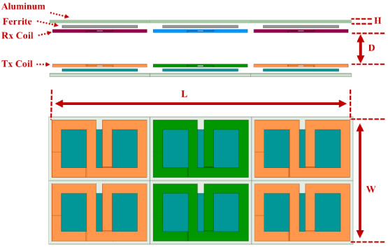
Design parameters of wireless power transfer system.
Parameters of the WPT system
Magnetic fields and the consequent MFL are present in all operating conditions of a WPT system, i.e. both in the nominal mutual position between transmitter and receiver as well as in the presence of misalignment and up to the nominal values of currents and transmitted power. Misalignment is often considered as an undesired working condition, for this reason in many realizations the control system may reduce power under misalignment or large clearance conditions; however, MFL usually increases in case of misalignment, and this operating condition must be properly evaluated especially in dynamic WPT. MFL emissions obviously increase with current through the transmitter and receiver coils with linear dependence if the ferrite bars are not saturated. In order to better analyze the shielding effect of dynamic wireless charging, in this paper a study under the maximum condition of coil misalignment and the maximum current flowing through the GA and/or VA coil is carried out. According to the standard of SAEJ2954, the maximum misalignment between VA and GA coils is y = ±100 mm and x = ±75 mm (Table 2).
Ground clearance operating range requirements for product gas
Ground clearance operating range requirements for product gas
Using the FE 3D model of the wireless charging system, the leakage magnetic field has been calculated; the field maps are shown in Fig. 4(a) and (b). In the vertical direction, due to the existence of the large rectangular aluminum plate, the MFL is negligible. On the contrary, in the horizontal direction, there is a large MFL. As shown in Fig. 4(c) and (d), in the case of maximum misalignment (i.e. 𝛥X = 75 mm and 𝛥Y = 100 mm) of the transmitter and receiver coils, the MFL increases significantly.

(a) 3D Magnetic field map under perfect alignment conditions. (b) Cross-sectional magnetic field map under perfect alignment conditions. (c) 3D Magnetic field map under misalignment conditions. (d) Cross-sectional magnetic field map under misalignment conditions.
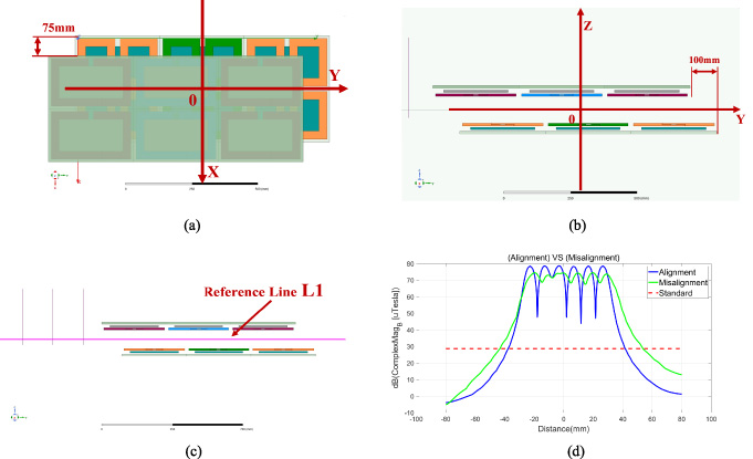
The qualitative analysis depicted in Fig. 4, shows that both conditions (perfect alignment and maximum misalignment) must be studied in order to properly design the shielding system. Figures 5(a) and (b) show the reference system used throughout the paper; in addition, Fig. 5(c) shows the “reference line L1” in the middle of the Tx and Rx coils along the y axis, used for the field evaluation and comparison reported in Fig. 5(d). According to the guidelines, the reference level for public exposure is 27 μT from 3 kHz to 100 kHz [3].
Figure 5(d) shows the magnetic flux density generated along line “L1” for both cases (perfect alignment and maximum misalignment). In both cases, the magnetic field strength between the two pads is large. The red line in the Fig. 5(d) indicates that the value of magnetic field strength is 27 μT. Obviously, it can be concluded that the MFL is more widely distributed in the case of misalignment. Effective shielding methods are needed to suppress EMF emissions in high-power charging systems with higher misalignments.
Magnetic field magnitude along the Y axis. (a) In the top view, the receiving coil is offset by
The function of the shield is to reduce the MFL during the energy transmission between the pads. However, as a side effect, there is a reduction of the system performance because of the losses in the shield and the reduction of the field also in the active region. From the circuital point of view, shielding coils are additional circuits coupled to the Tx and Rx coils, and they react according to the well-known Faraday–Lenz principle. In Section 3 the shield model used for the simulations is discussed.
Different countries and regions have established regulations and standards to limit human exposure to EMF emissions. These standards typically specify maximum allowable levels for electric and magnetic fields that should not be exceeded to protect public health. WPT systems for EVs are designed to minimize EMF emissions and ensure compliance with relevant safety guidelines. This includes optimizing the design and configuration of charging systems, implementing shielding and grounding techniques, and utilizing appropriate components to minimize electromagnetic radiation. In general EMF emissions from WPT systems decrease with distance from the pad assembly, but we have to consider that as the distance between the pads increases the MFL increases. According to the recommendation of SAEJ2954 technical specification, the operating frequency of wireless charging system for electric vehicles is set in the range: 81.3–90 kHz.
Human EMF exposure standard, reference levels
Human EMF exposure standard, reference levels
1. When using 100 cm2 three-axis standard field probe for magnetic field measurements.
For human EMF reference level assessments, the minimum working distance shall be chosen such that compliance with the reference levels (Table 3). Design considerations take into account safe operating distances to maintain EMF levels within acceptable limits. Prior to the deployment of WPT systems, electromagnetic field exposure assessments are often conducted to evaluate the potential impact on human health and ensure compliance with relevant regulations. These assessments consider factors such as field strength, exposure duration, and the proximity of sensitive areas (e.g., areas potentially accessible to human beings) to the charging system. It is important to note that ongoing research and advancements in WPT technology aim to further reduce EMF emissions and improve safety.
Proposed shield model
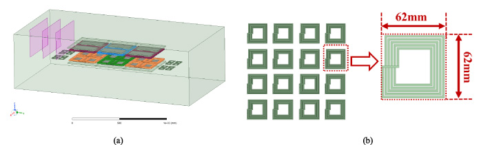
According to previous studies, if a single rectangular coil is used for shielding purpose, an opposite magnetic field is produced in correspondence of the inner portion of the coil with a reduction of the original magnetic field, while the magnetic field is increased in the outer part of the coil. The shielding effect is limited to the regions facing inner part of the coil. In order to overcome this issue, a design consisting of four 4 × 4 matrix coils is considered, which cancels mutual magnetic field enhancement effects, giving a relatively smooth and good overall shielding effect. The shielding coil matrix proposed in this paper is conceived to be used with the WPT system previously proposed by the authors and dedicated to dynamic charging [12], so the shielding coil is placed on the sides (and on the same plane) of the GA. It is composed of small square coils with a size of 62 × 62 mm, which are placed symmetrically on both sides of the GA coil, as shown in Figs 6(a) and 6(b). The self-inductance value of a single shielding coil is 1.65 μH; it is evaluated considering a stand-alone coil surrounded by media characterized by zero conductivity and unit relative magnetic permeability.
The proposed WPT system with resonant coil matrix shielding.
As the WPT system proposed above, the structure and relative position of the coils are given, and the corresponding parameters and coupling coefficients of the transmitting and receiving coils can be obtained. The design of a resonant coil matrix can be made simpler and faster compared to a FE model simulation, by using a circuital model of the system. The load resistance of each coil is mostly made up of its own wire resistance, so it is very small, and a relatively large current can flow in the coil with small losses. The magnitude of these currents and their phases depends on the “degree” of resonance which can be established by properly choosing a series capacitor.
The scheme of the proposed WPT system with resonant coil matrix shielding.
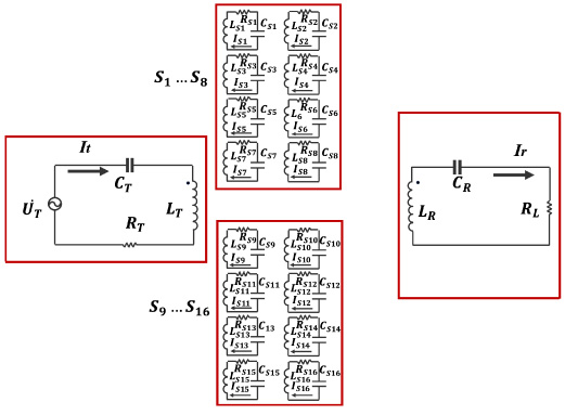
The equivalent circuit model of the wireless charging system with resonant coil matrix shielding is shown in Fig. 7. This is composed of Kirchhoff Voltage Low (KVL) equations involving the transmitting coil, the receiving coil, and the resonant coil matrix, respectively.
The coils of the shield matrix are defined as S1, S2, …, S n . Correspondingly, L S 1 , L S 2 , …, L S n represent the self-inductance of each single coils. C S 1 , C S 2 , …, C S n represent the lumped capacitor added to each single coils. There is magnetic coupling between all the coils throughout the system. The mutual inductance between the shielding coils MS j , S k (j =1, …,16, k =1, …,16, j ≠ k) and between the shielding coils and the receiving coil MR, S k (j = 1, …,16) are very low. Table 4 shows the order of magnitude of the circuit parameters.
Equivalent circuit parameters
In particular, the latter have little impact on the shielding properties because the shielding coil matrix structure developed in this article is small and placed close to the transmitting coil. As a result, MT, R, MT, S1, MT, S2, …, MT, S
n
are the most relevant quantities for the optimal shield design.
From Eqs (5)–(7), the output current
(a) Optimum magnetic field distribution of transmitting coil and shielding coil (b) Leakage field evaluation reference planes.
Frequency behavior of the currents.
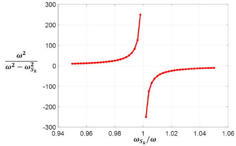
According to the Eq. (10) (represented also in Fig. 9), it can be easily concluded that the resonant frequency 𝜔
S
k
of the shielding coil should be only slightly bigger than the resonant frequency 𝜔 of the WPT system, so that a larger shielding coil current
This expression is valid for operating frequency that makes the reactance of the coil great enough w.r.t. the resistance.
The current in the transmitting coil is:
According to the currents obtained above, the efficiency of the system can be calculated as:
It can be seen from formula (11), that since R1…R k are all very small, the losses generated are also small, which will slightly decrease the WPT efficiency. According to the 3D-FEM simulation results, the induced voltage and current of the shielding coil are obtained, and the loss of the shielding coil is calculated to be around 100 W. For a 3.5 kW WPT system, the overall transmission efficiency will be slightly reduced.
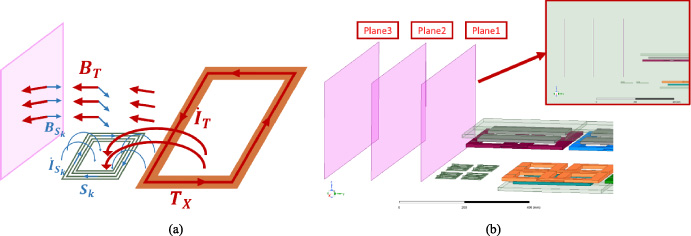
The shielding performance is evaluated by calculating the average value of the magnetic flux density magnitude (Eq. (13)) on three planes, parallel to the direction of movement in a zone potentially occupied by operators, as shown in Fig. 8(b).
We started considering the shielding coils as shorted without the presence of series connected capacitors. Based on the findings presented in Table 5, it is evident that the inclusion of shielding coils has a negligible impact on the effectiveness of shielding throughout the three testing planes. However, the average magnetic field intensities on test plane 1 and 2 exceed the international standard of 27 μT.
Shielding effect comparison
As observed in the previous section some form of resonance must be introduced to improve the shielding effect of a coil matrix; we will consider here passive resonance.
In order to achieve resonance near the operating frequency of the wireless charging system, lumped capacitors of different values can be added to the coil matrix, as shown in Fig. 10. In this first design study, all the coils are geometrically coincident, and homogeneous distributed on a prescribed area; moreover all the coils are tuned to the same resonant frequency, leading to S C 1 = ⋯ = S C i = ⋯ = S C n . The optimization of the shield’s performance might potentially be accomplished through the utilization of n different capacitors. However, it is important to note that this study does not encompass the pursuit of such fine-tuning. In addition, such fine tuning would require an extremely accurate knowledge of the quantities involved in the design process of the whole WPT system (geometry and material characteristics); furthermore, a sensitivity analysis would be required, in order to evaluate the effect of the tolerance of the capacitor nominal value.
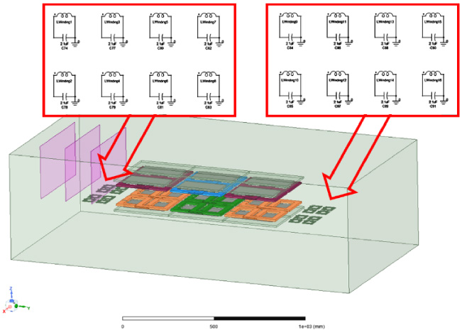
Passive resonant coil matrix.
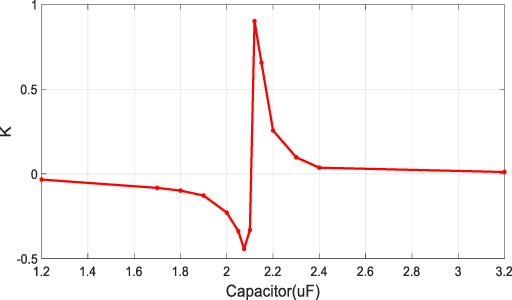
To determine the optimum tuning of the superior shield, a research study is done using lumped capacitors with varying values. The objective is to examine the average magnetic flux leakage intensity on Plane 3 in relation to the parameter K, as defined in Eq. (14). The results are shown in Fig. 11.
Shielding effect with coil catrix VS without coil matrix.
In the given system, if the capacitance value is lower than the threshold required for resonance at the operating frequency, the coil matrix demonstrates a capacitive characteristic, resulting in a good shielding effect. When the capacitance value is high, the coil matrix demonstrates an inductive characteristic, leading to a decline in shielding efficiency and potentially worsening the MFL. Based on the preceding theoretical analysis, it can be inferred that there exists a positive correlation between the shielding effect and the current of the shielding coil, denoted as
Shielding effect with different capacitance values.
Average of magnetic strength
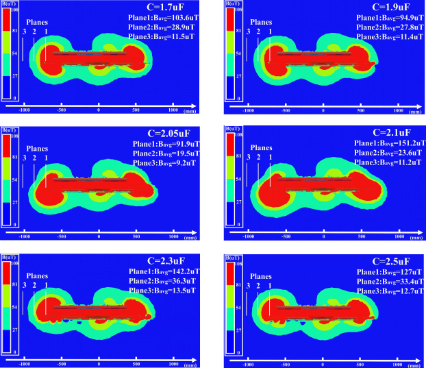
As shown in Fig. 12, in the case of different capacitance values, it can be seen that the magnetic field strength also changes accordingly. Among them, the blue area indicates that the magnetic field strength is less than 27 μT, which means that this area belongs to the safe range. When the capacitor C = 2.05 μF, the average magnetic field intensity of test planes 2 is 19.5 μT, in Table 5. Compared with unshielded coils, it is reduced by 37%, that is a significant shielding performance. Furthermore, it can be seen from Fig. 12 that when good shielding performances is achieved, the leakage field shape is changed, and the region with more intense flux density is “pushed into ground”. It is also interesting to observe that plane 1 is expected to lay is a region usually not allowed for pedestrians, unlike planes 2 and 3.
In this paper, we propose a resonant coil matrix shielding method for wireless power transfer in electric vehicle systems. With the originally proposed coil matrix, the coil coupling resonance is achieved through passive method at the operating frequency of the wireless charging system to achieve the best shielding result. The passive resonant only needs lumped capacitors, which are lower in cost but prone to reverse effects. This method combines efforts in mathematical model, 3D simulation, and design methods, which can be further applied to the shielding problem of wireless charging. Therefore, we believe that the proposal presented in this paper can enable the efficient design of shielding configurations for WPT systems in EV applications.
Footnotes
Acknowledgements
This work was supported in part by the European Union—Next Generation EU through the Grant “PNRR MUR—M4C2—Investimento 1.4—Avviso Centri Nazionali— CN00000023 Sustainable Mobility Center” and in part by REACT-EU PON “Ricerca e Innovazione 2014-2020 Azione IV.5 Dottorati su tematiche Green.”