
Abstract
A coaxially integrated macro-micro composite actuator (MMCA) with large stroke and high accuracy is proposed by combining a voice coil motor (VCM) with the giant magnetostrictive actuator (GMA). The magnetic circuit model of the macro-motion part is established based on the driving principle of VCM, and the multi-field coupling model of the micro-motion part is established based on the Jiles-Atherton model. The finite element method was used to analyze the relationship between displacement, output force, velocity, acceleration, and time of the macro-motion part under different currents, the magnetic flux density, output force, and displacement curves of the micro-motion part, and the mutual influence between the macro and micro motion parts were analyzed. The prototype of the MMCA was developed, and an experimental test platform was built. The results show that the MMCA macro-motion displacement curve can fit the simulation curve well during open-loop positioning, and when the current size of the input macro-motion coil is 4 A, the experimental curve of the MMCA is the most consistent with the simulation curve. When closed-loop control, the motion curve of the drive can well follow the set displacement curve, in which the maximum stroke of the prototype developed is 50 mm, the positioning error of the macro-motion part is less than 20 μm, the maximum stroke of the micro-motion part is 40 μm, and the overall positioning accuracy of the MMCA is 0.14 μm. The research results provide a new idea and theoretical basis for further optimization and development of precision positioning platform with high precision and large stroke.
Keywords
Introduction
The precision motion workbench with high-precision positioning characteristics is the core functional component of high-end parts processing such as micromachining and testing [1]. Widely used in bioengineering [2], MEMS instruments and equipment [3], precision optical systems [4–6], chip processing [7,8] and other high-precision fields [9–11]. In recent years, with the deepening of research in various fields, people have put forward higher requirements for the performance index of precision motion workbench, such as larger stroke, higher positioning accuracy, more reasonable structure, and so on. Therefore, the development of a precision motion workbench with large stroke and high positioning accuracy is of great significance for breaking through the corresponding bottlenecks in many research fields.
However, there is a contradiction between large travel and high precision. To solve this contradiction, scholars at home and abroad have carried out a lot of research and mainly proposed two solutions, one is a unipolar drive and the other is a macro-micro composite drive. In terms of unipolar drive, the research of domestic and foreign scholars mainly focuses on the transmission mechanism, that is, based on maintaining the positioning accuracy of the drive, the maximum stroke is increased by rushing the transmission mechanism and optimizing the control method [12,13]; in terms of a macro-micro composite drive, the research direction of domestic and foreign scholars mainly focuses on the macro-micro driving actuator, that is, by changing the combination form of different driving methods, increasing the stroke of the motion workbench and improving the positioning accuracy of the workbench. For example, Ito S et al. [14] of the Technical University of Vienna, Austria, designed a flexible hinge-guided nano-positioner with a nonlinear hybrid reluctance brake, with a motion stroke of 2 mm and a minimum positioning accuracy of 2 nm; Lushen Yuan et al. [15] designed a piezoelectric stage with a maximum displacement of 30.76 μm in a single direction and a minimum resolution of 29.3 nm; JingShu Wang et al. [16] developed a dual-drive positioning system, in which the long stroke is mainly provided by the main positioning stage, and the precision positioning system is realized by the PID controller, which ensures that the system has a stroke of 120 μm and a positioning accuracy of 7 nm; Lanyu Zhang et al. [17] designed a macro-micro composite actuator, in which the macro and micro motion are driven by VCM and PZT1 actuators respectively, and have a positioning accuracy of ±3 μm within a stroke of 40 mm; CHEN Chao et al. [18] developed a positioning workbench driven by a linear piezoelectric drive, and obtained that its motion stroke is 55 mm and the positioning error is 0.5 μm through experimental research.
In summary, most scholars at home and abroad adopt macro-micro composite to solve the contradiction between large-stroke and high-precision, one of the driving structures of macro-micro composite is stacked (micro-motion workbench placed on the macro-motion workbench) [19], and the other is to unify the axis of macro and micro motion workbench into a straight line through the connecting frame [20]. Among them, although the stacked superimposed type is simple to install, the macro and micro actuator are not on the same axis, there will be an Abbe error during positioning, which will affect the positioning accuracy of the device; in the coaxial type, the two axes of the macro and micro actuator are aligned with each other, which can avoid the Abbe error during positioning.
Because of the above problems, by comparing the working principle of VCM [21,22] and GMA [23,24], the team designed an MMCA that combines the high-speed and large-stroke characteristics of VCM with the high-speed and high-precision characteristics of GMA. To accurately analyze the macro-motion characteristics of the MMCA. Through the simulation analysis of the performance curve of the macro and micro part of the MMCA and the influence between the macro and micro motion, the rationality of the design solution is verified. Based on the development of the MMCA prototype, an experimental platform is built to test the positioning performance of the MMCA. The research results provide new ideas and a theoretical basis for further optimization and development of a precision motion workbench with high accuracy and large stroke.
Based on the team’s previous research [25,26], this paper mainly studies the operating curve and positioning performance of the MMCA under different currents. In the second section, the internal structure of the MMCA and its working principle are introduced; In the third section, the mathematical model of the MMCA is established, and the relationship between the input voltage and the displacement of the macro-motion part is obtained, and the displacement-magnetostrictive strain model, the displacement-output force model and the output force-magnetostrictive strain model of the micro-motion part are obtained. To obtain the performance curve of the MMCA under different currents, an electromagnetic simulation analysis is carried out in the fourth section. The fifth part tests the performance of the MMCA by building an experimental platform. The sixth section is the conclusion of the paper.
Working principle
As shown in Fig. 1, it is the coaxial integrated MMCA is mainly composed structural schematic diagram of two parts: macro-motion and micromotion. The MMCA, in which the blue dotted box is the macro-motion part is similar to the dynamic VCM, which mainly provides the large long-stroke motion of the MMCA; movement; The red dotted line box is the micro-motion part is GMA, which relies on the magnetostrictive effect of giant magnetostrictive material (GMM) to generate output force and displacement on the load, and its main function, which is mainly used to compensate for the macro-motion positioning error of macro-motion with high precision. Wherein the macro-motion part and the micro-motion part are separated by a magnetic isolation cylinder made of non-magnetic materials.
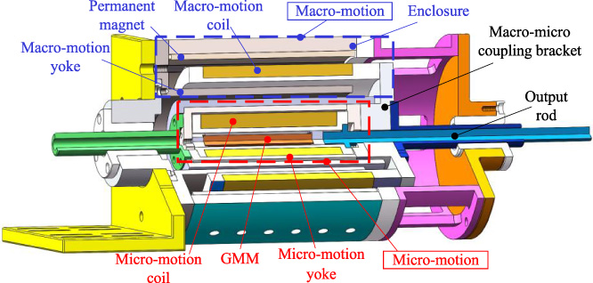
Schematic diagram of the MMCA structure.
The macro-motion part of the MMCA is mainly composed of an enclosure (made of soft iron DT4C), a macro-motion yoke, a permanent magnet, and a macro-motion coil. The magnetic field generated by the permanent magnet forms a loop after passing through the yoke. When the macro-motion coil is energized, it will generate an output force and displacement S a to the macro-micro combined bracket due to the action of Ampere's force, and then drive the micro-motion part connected to the macro-micro combined bracket to move. This process is called the macro positioning stage. The output force and displacement generated by the micro-motion part are mainly caused by the magnetostrictive effect of the GMM rod under the excitation magnetic field generated by the coil, and then the output force and displacement S i are generated to the outside through the output rod, to achieve high-precision positioning compensation for the macro-motion part. Assuming that the required displacement is S, the positioning error of the final MMCA is |S − (Sa + S i )|, and its working process is shown in Fig. 2.

Working principle diagram of the MMCA.
Mathematical model of the macro-motion part
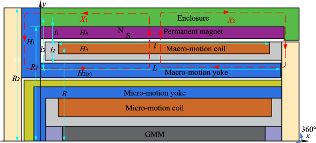
Figure 3 shows a cross-sectional diagram of the MMCA. R is the average radius of the macro-motion coil; L 1 is the thickness of the permanent magnet; S and N are the magnetic poles of the permanent magnet; l is the length of the macro-motion coil; H 1–H 4 is the magnetic potential of each point in the magnetic circuit; X 1 and X 2 are magnetic field line circuits.
Schematic diagram of the MMCA.
Assuming that the working air gap and the magnetic potential in the permanent magnet are uniformly distributed, the magnetic field lines in X
1 and X
2 are evenly distributed, the coil, yoke, permanent magnet, etc. are ideal materials, the permeability of the permanent magnet and the working air gap is equal, and the magnetic leakage effect at the opening of the MMCA is negligible, the magnetic potential of the flux path in Fig. 3 is:
The magnetic density distribution of the working air gap after Eq. (3) is brought into Eq. (2) is shown in Eq. (4), where k is the coefficient. Then the force balance equation shown in Eq. (5) is obtained by force analysis of the macro-motion part of the MMCA.
When direct current is applied to the coil, the macro-motion coil will be axially moved by ampere force, and then the back electromotive force U
e
will be generated. The voltage balance equation for the coil loop is shown in Eq. (6), and by combining Eqs (5) and (6), Eq. (7) can be obtained.
According to Eq. (8), the mathematical model block diagram of the macro-motion part is obtained, as shown in Fig. 4.
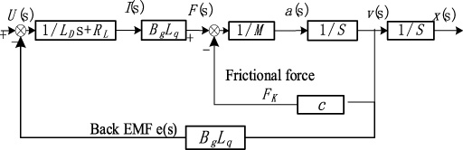
Mathematical model of the macro-motion part of the MMCA.
In the micro-motion part of the MMCA, there is a hysteresis non-linearity between the input magnetic field of the GMM and the output magnetization intensity due to the irreversible magnetization of the ferromagnetic material. The Jiles-Atherton model is a hysteresis model based on the domain wall theory of ferromagnetic materials [27]. Therefore, this paper establishes a hysteresis model of the micro-motion part based on the Jiles-Atherton model.
According to the [28], the relationship between the magnetostrictive strain 𝜆 and the magnetization intensity M
1 of the GMM rod satisfies a certain magnetic field strength:
Since the hysteresis model of GMA is based on the Jiles–Atherton model, there are 6 parameters to be identified in the displacement model of GMA, namely 𝜃 = (M s , 𝛼, q, a 1, c, 𝛾). where c is the reversible component coefficient; 𝛼 is the domain-wall interaction coefficient; q is the irreversible loss coefficient; a 1 is the shape coefficient of hysteresis-free magnetization strength; M s is the saturation magnetization strength. For the subsequent analysis, the values of the parameters in the hysteresis model need to be known, and the results of the PSO-AF parameter identification optimization algorithm [29] are cited here, with the values of the parameters shown in Table 1.
Parameter values of an actuator hysteresis model
According to Table 1, and using Eq. (9), the numerical solutions of M 1 and 𝜆 under the action of H can be obtained.
Since the micro-motion part of the MMCA is GMA, it can be approximated that the GMM rod in the axial direction is composed of three parts of a single-degree-of-freedom separation element spring, damper, and load, considering the pressure connection stiffness, the load (including disc spring, output rod, mass load) is a mass-spring-damping load [30], and during the whole motion, the displacement of one end of the GMM rod is 0 and the other end always maintains the same displacement, velocity, and acceleration as the mass load. Let K G , C G , and M G be the equivalent stiffness coefficient, equivalent damping coefficient, and equivalent mass of GMM rod, respectively. K L , C L , and M L are the equivalent stiffness coefficient, equivalent damping coefficient, and equivalent mass of the load, respectively. In summary, the equivalent dynamical system of the micro-motion part is schematically established as shown in Fig. 5.
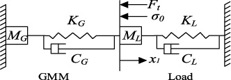
Schematic diagram of micro-motion dynamics of the MMCA.
The nonlinear magnetic equation based on GMM rod characteristics, mass, and damping is [31]:
From the schematic diagram of the dynamics of the micro-motion part, it can be seen that the force F
t
of the load M
L
on the GMM rod and the force F
q
of the GMM rod on the load (that is, the output force of the micro-motion part) are a pair of interaction forces, equal in size and opposite in direction, that is:
Considering also that the GMM rod is prestressed 𝜎0 by the pre-tensioning screw and the disc spring, according to Newton’s second law, the output force of the GMM rod is F = −(F
q
+ 𝜎0 A), that is:
From the strain 𝜀 = x
1∕L, Eq. (10) and (12) are connected, the dynamic equation of the micro-motion part can be obtained, and it can be obtained by Laplace transform. But considering that the GMM rod is always subjected to the pretensions screw and the prestressed 𝜎0 action of the disc spring, the displacement (the measured value of the displacement transducer) that the relative equilibrium state of the micro-motion part ultimately exhibits is Eq. (13), and the mechanical resonance frequency f of the micro-motion part is Eq. (14).
From Eq. (13), the output displacement-magnetostrictive strain model of the micro-motion part is:
Applying the Laplace transform to Eq. (11), the displacement-output force model for the micro-motion part is obtained as:
Substituting Eq. (15) into Eq. (16) yields, the output force-magnetostrictive strain model of the micro-motion part is:
Finite element analysis of the macro-motion part
The simulation model of the MMCA is established by COMSOL Multiphysics simulation software. Because MMCA is a cylindrical structure, only the axial section is established in the software to improve the calculation speed. The main simulation parameters of the MMCA are shown in Table 2, in which the residual magnetic flux density modulus of the permanent magnet is 1.35 T and the saturated magnetostrictive coefficient of the GMM rod is 900 ppm. By checking the quality of the grid, the minimum unit mass of the grid is 0.41, the average unit mass is 0.79 and the relative tolerance is 0.001, which meets the requirements of electromagnetic simulation.
To obtain the optimal current size of the MMCA during operation, different current magnitudes were used to simulate each of the 50 mm strokes, and the curves of displacement relationship to time, output force relationship to time, velocity relationship to time, and acceleration relationship to time were obtained as shown in Fig. 6.
Main simulation parameters of the MMCA
Main simulation parameters of the MMCA
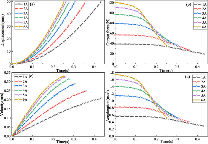
Macro-motion part performance simulation curve of the MMCA (a) displacement relationship to time, (b) output force relationship to time, (c) velocity relationship to time, (d) acceleration relationship to time.
It can be seen from Fig. 6(a) that with the current gradually increasing from 1 to 6 A, the time for the MMCA to reach the 50 mm stroke is gradually shortened. It can be seen from Fig. 6(b) that with the increase of current from 1 to 6 A, the output force of the device at the initial moment is also increasing. When the MMCA is displaced, the relative position of the macro-motion coil and the permanent magnet changes, so the output force begins to decrease with the increase of time. As shown in Fig. 6(c) and (d), with the decrease of output force, the acceleration of the device is gradually decreasing, so the speed growth trend of the device is gradually slowing down, and because the acceleration is proportional to the out-put force, the acceleration, and the output force have similar changing trends. As can be seen from Fig. 6, when the input current is 1 A or 2 A, although the output force is relatively gentle, the initial acceleration is small because the maximum output force is less than 60 N. When the input current is 3 A or 4 A, the maximum output force is about 80 N and 100 N, respectively, and the initial acceleration is large, and the fluctuation of force is about 50 N during the movement to meet the use requirements. When the input current is 5 A or 6 A, although the output force is greater than 100 N, it fluctuates greatly in the whole stroke. Therefore, if we want to obtain a smooth output force fluctuation and a large initial speed, it can be concluded from simulation analysis that 4 A is the optimal current when the macro-motion part of the MMCA is running.
As shown in Fig. 7, when the current through the macro-motion coil is 4 A, the magnetic field distribution of the MMCA is obtained by finite element simulation during motion.
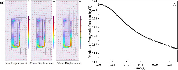
(a) Simulation of magnetic flux density within the stroke of the macro-motion part. (b) Variation of flux density within the stroke of the MMCA.
As can be seen from Fig. 7(a), it can be seen that the magnetic saturation is reached at the bottom of the macro-motion yoke, while there is a small amount of leakage at the opening, which is similar to the end effect of the VCM. During the whole stroke, the magnetic lines of force of the macro-motion coil return to the enclosure through the macro-motion yoke to form a circuit, which makes the magnetic field strength of the macro-motion coil inside it increase and increases the utilization of the macro-motion magnetic field.
As shown in Fig. 7(b), the trend of the magnetic flux density at the center of the macro-motion coil with the increase of the MMCA displacement when the macro-motion coil is fed with 4 A current. It can be seen that the flux density is gradually decreasing, which is consistent with the decrease of the output force with the increase of displacement in Fig. 6(b).
Since both macro and micro motion parts of the MMCA are driven by magnetic fields, the interaction between macro and micro motion magnetic fields should be minimized during the structure design. Therefore, electromagnetic field simulation is used to obtain the influence of the macro-motion coil current on the micro-motion magnetic field and the influence of the micro-motion coil current on the macro-motion magnetic field respectively.
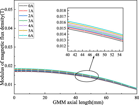
Effect of macro-motion coil current on the micro-motion magnetic field.
From Fig. 8, it can be seen that as the current through the macro-motion coil varies greatly from 0 to 6 A, the fluctuation of the magnetic field at the axis of the GMM rod is less than 0.002 T, so it can be neglected. the intensity of the magnetic field at the axis of the GMM rod gradually decreases from the bottom of the micro-motion to the outside, a phenomenon related to Fig. 7(a), due to the existence of magnetic saturation at the bottom of the macro-motion part, which makes the magnetic field of the macro-motion yoke gradually decreases from the inside to the outside.
To verify the effect of the micro-motion coil current size on the macro-motion magnetic field, the electromagnetic field simulation is carried out, setting the micro-motion coil current variation range from 0∼6 A, and the macro-action coil is fed with 4 A current, selecting an axis at the macro-motion working air gap, and obtaining the curve of its average flux density variation as shown in Fig. 9.
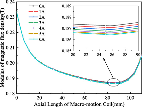
Effect of micro-motion coil current on the macro-motion magnetic field.
From Fig. 9, it can be seen that as the current through the micro-motion coil changes from 0∼6 A, the magnetic field generated in the micro-motion part has less than 0.001 T effect on the macro-motion magnetic field, so it can be considered that the micro-motion coil current has almost no effect on the macro-motion magnetic field. The reason for the change of magnetic field at the macro-motion working air gap shown in Fig. 9, which first decreases and then increases, can also be seen in Fig. 7(a), because the magnetic saturation phenomenon occurs at the bottom of the macro-motion yoke and the housing of the macro-motion part, and gradually decreases from the inside to the outside, and when it reaches near the opening of the MMCA, the magnetic flux of the enclosure also increases, so that the magnetic field at the working air gap also becomes larger.
The above research results show that the interaction between the macro and micro motion parts of the MMCA is almost negligible, which proves the reasonableness and feasibility of the structure design.
Since the MMCA operates with coarse positioning of the macro-motion part followed by high-precision positioning compensation by the micro-motion part, the magnitude of the displacement generated by the micro-motion part also determines the magnitude of the macro-motion positioning error that can be compensated, so the positioning accuracy of the MMCA mainly depends on the positioning accuracy of the micro-motion part. To further study the positioning accuracy of the MMCA, the magnetic field simulation of the micro-motion part is carried out to study the stress and the magnitude of strain generated by the GMM rod in the micro-motion magnetic field. As can be seen from Fig. 10. shows the magnetic flux density distribution of the micro-motion part when 5 A current is applied to the micro-motion coil.

Magnetic flux density distribution of the micro-motion part.
As can be seen from Fig. 10, the magnetic flux density of the micro-motion part gradually decreases from the bottom end of the device to the outside, because the micro-motion yoke is closed at the bottom of the MMCA, and the front end of the micro-motion part has an output rod made of non-conductive magnetic material, making the magnetic flux density of the right end less than that of the left end.
Figure 11. shows the magnetic flux density, micro-motion displacement, and output force versus micro-motion coil current magnitude for the micro-motion portion of the MMCA.

(a) variation of the flux density at different micro-motion coil currents. (b) Micro-motion displacement and output force versus micro-motion currents.
As can be seen from Fig. 11(a), the flux density increases as the current through the micro-motion coil increases, but gradually decreases as the GMM rod moves from left to right, which is consistent with the magnetic flux density cloud shown in Fig. 10. As can be seen from Fig. 11(b), the stress and strain on the GMM rod increase as the current through the micro-motion coil increases, reflected in the increased displacement and output force of the micro-motion part.
To obtain the vibration characteristics of the MMCA and verify the rationality of the design, the modal analysis of MMCA is carried out by Ansys Workbench, and the natural frequencies in its main motion direction are obtained. The results are shown in Fig. 12.
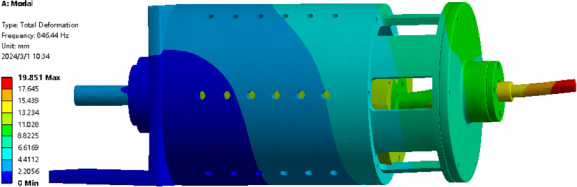
MMCA first-order mode.
As can be seen from Fig. 12, the first-order natural frequency in the main working direction of MMCA is 846.44 Hz, the effective mass Ratio at this time is 95%, and the ratio is 1. It can be considered that the natural frequency at this time is the vibration frequency in the moving direction of the MMCA.
Because the MMCA will be subjected to the axial force of the output rod when working, it is necessary to simulate the structural strength of the MMCA to determine whether the structural design of the MMCA meets the requirements. As shown in Figs 13 and 14, the structural strength of the MMCA is simulated and analyzed by Ansys Workbench, in which the output rod is made of aluminum alloy 6061 T6, and the axial force along the output rod is set to 200 N according to the output force of the macro-motion part of the MMCA.
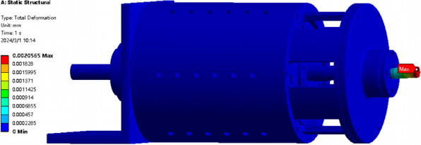
Total deformation program of the MMCA.
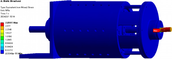
Equivalent stress program of the MMCA.
As can be seen from Figs 13 and 14, after an axial force of 200 N is applied, the maximum deformation of the MMCA is 0.002 mm and the maximum equivalent stress is 2.8991 MPa. Therefore, the structural design of the MMCA is reasonable, and it can be used to obtain higher system stiffness by changing the material of the output rod.
Prototype testing
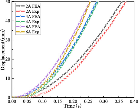
To further test the performance of the MMCA, a prototype of the MMCA was developed and a performance test platform was built. The performance parameters such as the maximum stroke and positioning accuracy of the MMCA are obtained by testing. As shown in Fig. 15, it is the test platform of the MMCA, which mainly includes the prototype of the MMCA, grating sensor, switching power supply, PC, data acquisition card, and DSP control board. As shown in Fig. 16, it is the control strategy diagram of the MMCA. The motion characteristics of the MMCA measured by experiments at different current levels are shown in Fig. 17.

Experimental test platform of the MMCA.

Control scheme of the MMCA.
Macro-motion part displacement test of the MMCA.
As can be seen from Fig. 17, the motion of the MMCA during the experiment is the same as that of the simulation, when the current into the macro-motion coil is 2 A, the displacement curve of the experiment is slower than that of the simulation due to the presence of static friction, but the curvature of the second half of the displacement is the same. When the current through the macro-motion coil is 4 A, the time required to overcome the static friction is shorter, but the curvature of the second half of the displacement is also the same as the simulation, showing a highly parallel state. Therefore the optimum value of current for the macro-motion part of the MMCA is 4 A.
The stroke curve of the micro-motion part of the MMCA is shown in Fig. 18. To test the repeatable positioning accuracy of the macro-motion part of the MMCA, 4 A current was first applied to the micro-motion part and kept constant, keeping the GMM rod with an elongation of about 20 μm, and then 4 A current was applied to the macro-motion coil. According to different working conditions, several positioning experiments are conducted by setting different target points, as shown in Fig. 19, in which the blue horizontal line is the set target point and the light yellow area is the micro-motion part, which can be obtained by changing the current of the micro-motion coil.

Micro-motion part stroke.
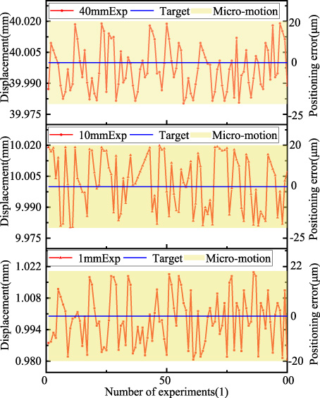
Open-loop test positioning error of the MMCA.
From Fig. 18. can be obtained that with the increase of the micro-motion coil current, the displacement of the micro-motion part is also gradually increasing, but the magnitude of the increase is gradually decreasing, at the current size of 6 A, the displacement is 40 μm. As can be seen from Fig. 19, when conducting positioning experiments of 1 mm, 10 mm, and 40 mm, the repeated positioning error of the macro-motion part of the MMCA is within ±20 μm, and the stroke of the micro-motion part can fully compensate for the error during macro-motion positioning.
As can be seen from Figs 17 and 18, the maximum macro stroke of MMCA is 50 mm, and the maximum micro stroke is 40 μm. The maximum stroke of the macro-motion part determines the maximum distance that MMCA can execute, while the maximum stroke of the micro-motion part determines the size that MMCA micro-motion can compensate for the dis-placement error of the macro-motion part. Through finite element analysis and experiments, it can be known that the structure and control method of the MMCA can be optimized to obtain a longer stroke and faster response speed.
Figure 20 shows the performance test experiment of the macro-motion part of the MMCA at different strokes.

Macro-motion part performance test of the MMCA.
As can be seen from Fig. 20, the positioning error of the macro-motion part of the MMCA is less than 20 μm at 20 mm and 40 mm displacement, and the actual running curve of the macro-motion part can closely follow the set displacement curve, and its displacement following ability is good.
As can be seen from the MMCA positioning error diagram in Fig. 21, the overall positioning error is less than ±0.14 μm.
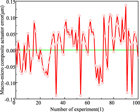
Positioning error curve of the MMCA.
The MMCA described in this article is paired with the same type of actuator shown in the previous study, as shown in Table 3. The MMCA proposed in this paper has a large stroke of 50 mm and a positioning accuracy of ±0.14 μm. The stroke of MMCA is 25 times that of reference [14]. Compared with reference [17], MMCA not only has a higher stroke but also has a higher positioning accuracy, which is similar to that in reference [18].
Performance comparison versus the previous actuator
Performance comparison versus the previous actuator
In this paper, an MMCA for precision positioning is developed by combining VCM and GMA. To verify the rationality and feasibility of the design solution, simulation analyses as well as experimental verification were carried out respectively, leading to the following conclusions:
(1) The optimum current size for the macro-motion part of the MMCA is 4 A when the actuator not only has a short time to overcome friction but also has the best fit between simulation and experiment.
(2) The negligible effect between the macro and micro motion parts of the MMCA illustrates the reasonableness of the design solution.
(3) The experimental test of the MMCA shows that the MMCA prototype can follow the set displacement curve well, the maximum stroke of the MMCA reaches 50 mm, the macro-motion positioning error is less than ±20 μm, the maximum stroke of the micro-motion part is 40 μm, and the overall positioning error of the MMCA is ±0.14 μm.
The results of the study show that the design solution of the coaxially integrated MMCA is reasonable and feasible. The proposed solution provides a new solution and technical basis for the optimization and development of future high-precision, large-stroke precision motion workbenches.
Footnotes
Funding
This document is the result of the research project funded by the National Natural Science Foundation of China (grant no. 52105042), (grant no. U21A20122), the China Postdoctoral Science Foundation (grant no. 2019M652159), the Anhui Provincial Natural Science Foundation (grant no. 2008085QE214), the Anhui University of Science and Technology Postgraduate Innovation Foundation (grant no. 2023cx2062), the Open Foundation of the State Key Laboratory of Fluid Power and Mechatronic Systems (GZKF-202302).