
Abstract
Electrical machines that can run at high speeds are more and more studied as they can respond to the increasing need of power onboard of aircrafts. However, to allow high-speed operability mechanical handling of the rotating parts need to be insured. In this paper an analytic design process of a novel high-speed induction machine is presented. The analytical magnetic and mechanical models developed are presented and validated with finite element simulations. The magnetic model is based on a classic equivalent electrical diagram of induction machine with a specific adaptation for the rotor leakage inductance as the squirrel cage is buried. The mechanical model is based on a field displacement approach leading to the stress tensor in all the rotating part. A four degrees of freedom vibration analysis model considering gyroscopic effects based on Euler–Lagrange equation allows to identify the critical speeds of the system. It is shown that some geometrical parameters will have opposed effects on the two physics. Thus, an optimization-based coupling between the different physics allows to design rapidly the desired machine regarding any technical specifications as analytical models are being used.
Introduction
In recent years, the trend towards electrification of different transportation systems has emerged in the aviation industry, posing new challenges for hybrid aviation in terms of embedded power generation system topologies [1]. Studies are being carried out to lighten the structure by proposing direct-drive generators on the turbojet reactor in order to tend towards high-speed systems. Thus, the increase in the operating speed of the machine makes it possible to reach interesting power densities but is also synonymous with many considerations regarding the mechanical behavior of the entire rotating system. The trail of the permanent magnet generators is under study and allows to obtain the first products ensuring operation to almost 40 krpm by supplying hundreds of kilowatts. The objective of this work is to apply the principle of high-speed induction machines (HSIM), widely used in oil and gas industry [2], at lower power and therefore compactness levels in order to study the applicability of this type of machine to transportation systems. As the design of this type of machines appeals to multi-physics considerations using finite element (FE) approach is time and resource consuming. [3] propose a new approach in order to reduce the computing time of a three dimensional optimization problem. A hybrid model based on 3D FEM and Permeance Network allows to give significant results with important time saving comparing to full 3D FEM method. In the current study it is chosen to use less CPU time consuming approach by developing analytical models of each physic. Each model developed aims to give the closest results to those provided by FE making the least possible simplifying assumptions. Also, the impact of the assumptions done on the results is discussed to identify whether they can be done or not. This will be an opportunity to examine both electrical and mechanical aspects to fulfill all the requirements. The third physic to account for when sizing an electrical machine is the thermal one and is not here presented but will have a direct impact as the mechanical and magnetic properties of the materials will change depending on their temperature. It will be considered in future work.
Structure of the HSIM
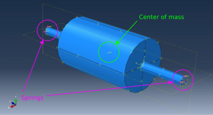
The HSIM principle is based on an observation which was notably demonstrated in [4] and widely illustrated in [5], stipulating that the achievable peripheral speeds for a hollow cylinder are much less important than that of a full cylinder. This is mainly due to the fact that the inertia constraints which will be established in the first case are almost double those in the second [4]. The HSIM rotor consists of a stack of laminated sheets connected on either side by two massive half-shafts as shown in Fig. 1.
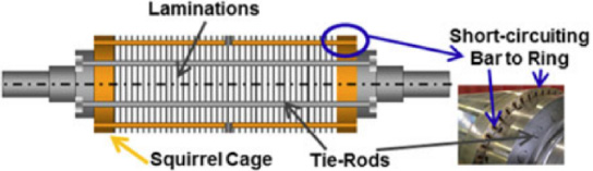
Structure of the HSIM [6].
Mechanical aspects of high-speed machine are considered in this paper, thus only the rotating part of the machine is optimized for a given stator. In the following results, the stator is considered composed of 24 slots with a double layer winding configuration. In order to minimize iron losses and reduce constraints regarding the control of this machine, the number of poles is reduced to p = 1. This leads to a 666 Hz frequency for the 380 V power supply. Two turns per slot is considered in the design allowing furthermore a hairpin winding. A classical shortening of the winding distribution of 11/12 is done to reduce some space harmonics. The airgap of the machine is set to 1 mm but has to be adjusted regarding the vibrational analysis results presented in the related part. The external radius is 84 mm with a bore radius of 56 mm and a height of the slots of 13 mm to provide the desired magnetic saturation in the ferromagnetic regions of the stator. This configuration is issued from a design for an electrical generator running at 40 krpm and providing a total power of 300 kW.
Due to the lack of a shaft through the rotor, the mechanical holding of the stacking of plates is granted by the presence of non-magnetic stainless-steel tie-rods (in grey on Fig. 1) which will be placed in such a way as to be able to tighten sufficiently the stacking of plates to each other. This stress adjustment is done by acting at the beginning of one of the two half shafts in order to reach the pressure for the mechanical holding of the assembly against the torsion. The rest of the HSIM structure is based on the conventional induction cage machine with copper bars placed on the periphery of the rotor and connected to each other by two short-circuit rings placed on both sides of the rotor (Fig. 1). It is important to note that the cage bars are not in direct contact with the air gap but are buried, with a distance defining the spoiler, for mechanical reasons. In this way, the rotor slots are closed and it is therefore necessary to size the cage to ensure that it is mechanically held and to guarantee magnetic coupling with the stator.
As shown in [2,4–6], the study of induction machines can be based on an equivalent single-phase electric circuit in which the value of the different components will directly depend on the parameters of the machine. This circuit pictures the operation of the induction machine as a rotating transformer with a transformation ratio K
T
see Fig. 2 where g denotes the slip.
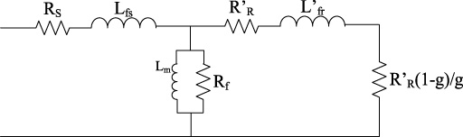
Equivalent scheme of the induction machine.
The results issued from the exploitation of this diagram allows to identify that the leakage inductances and especially those related to the rotor, as well as the rotor resistance has the strongest impact on the performances of the machine. Thus, a good modelling of the machine consists in a good evaluation of the stator and rotor leakage inductances.
Regarding the leakage inductance in the stator slots drawn on Fig. 3, an approach consisting of writing the expression of the magnetic energy stored in a rectangular slot allows to characterize the stator leakage flux.

Semi-open rectangular and cylindrical slots.
In the case of the calculation of the HSIM rotor leakage inductance, the same approach as that presented above cannot give a correct result since the distribution of the flux lines in a circular shape slot will be different from that of a rectangular one.
In [7] the authors studied the leackage inductance through a complete resolution of the Maxwell equations in a semi-open circular slot. It leads to an analytical expression of the reactance of a circular semi-open slot using Kelvin–Bessel functions and their derivatives:
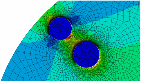
On one hand, Eq. (3) considers skin effect in the cage bars which leads to the dependency of leakage inductance to the frequency of the rotor currents. On the other hand, the frequency of stator currents leads to increase the equivalent resistance of the stator winding. This is accounted for when calculating the stator resistance by using Kelvin coefficient. Moreover, a given iron losses resistance is taken in the equivalent circuit and is evaluated for the fundamental frequency to include the impact of those losses in the model. In order to compare the results provided by this analytical approach, a finite element model on FEMM software is developed by considering two wires placed in two rotor slots whose dimensions can be changed (Fig. 4). For the stator part, a plate full of magnetic sheet is incorporated without accounting the stator slots but only the air gap in order to characterize leakage flux of rotor slots without the influence of the shape of the stator slots. Fig. 5, shows the evolution of L f r depending on the burial of the slot 〈d3〉 of the cylindric semi-open slot by the analytical model and FEMM. Thus, the analytical model allows to have a good evaluation of the leakage inductance of a cylindrical slot. The difference between the finite element and analytical results tends to decrease when increasing the burial of the slot. This can be explained by the fact that the flux lines tend to correspond to the ones assumed in the analytical model approach in these cases.

Model of rotor slots on FEMM.
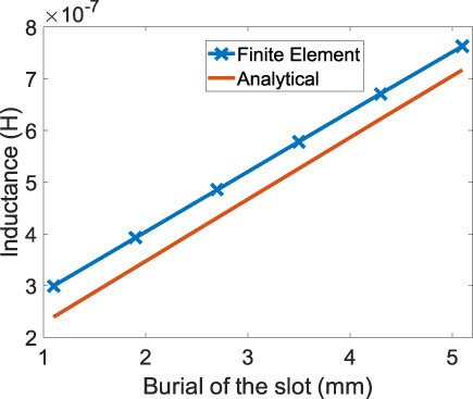
Evolution of the leakage inductance depending on the burial of the cylindrical slot (at f = 9 Hz).
In the scope of the HSIM, whose geometry was designed to meet the constraints related to high speed, the slots are closed. However, there is no analytical model of the leakage inductance of closed slots. In order to approach this physical reality, we consider semi-open slots that reflect the saturation of the spoiler (burial of the cage). The crucial question is to size the slot opening (s.o) so that the linear analytical model of a semi-open slot coincides with the numerical nonlinear model of the closed slot. By making a study in which the slot opening angle of the semi-open round slot 𝜃0 is decreased, it is then possible to tend towards the same values of leakage inductances of the closed round slot simulated by finite elements when the current density in the slot is around 7.5 A⋅mm−2 (220 A in Fig. 6). This value of current density will allow to not exceed 160 °C in the machine while using conventional air-cooling methods.
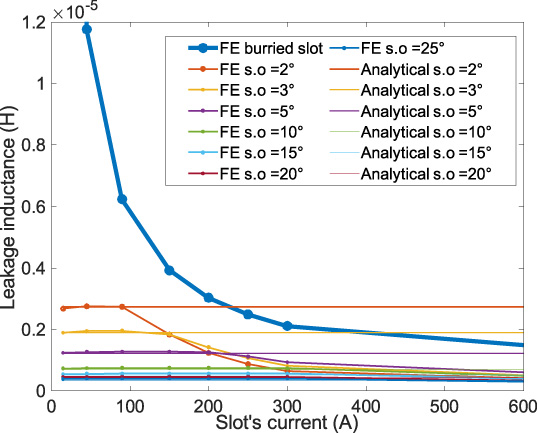
Current-dependent leakage inductance for different slot types.
In Fig. 6, the asymptotes at the origin of the curves representing the evolution of the rotor leakage inductance as a function of the simulated current by finite elements coincide exactly with the value which is calculated analytically. However, as the latter does not consider the non-linearity of materials, its value remains unchanged regardless of the current density in the conductor. Fig. 6 also shows that when increasing the slot opening, the input current in the slot has to be much higher to make the semi-open slot model and the real buried geometry coincide. The point of coincidence between the models will depend on the material property of the ferromagnetic circuit, specifically its B(H) curve. One can notice that it is possible to make the two models coincide for less slot’s current by making the slot opening even smaller that can be done rapidly thanks to the analytical model. Whereas with finite element this will involve to remesh the geometry with thinner elements and lead to drastically increase the computing time. Thus, when using the semi-open slot analytical model, it is good to know the targeted current density in the slot in order to choose the best slot opening angle.
Calculation of the stress in the rotor
The distance between the end of a bar from the cage to the air gap is defined as spoiler. As the bars are buried, the spoiler thickness is not null and will have to be determined so as to be able to withstand the forces due to the whole of the matter (cage, sheet, tie rods) which tends to move away from the center of rotation under centrifugal effects.
One of the analytical modelling approaches of mechanical behavior developed in [4] is used by extending the study to a multilayer rotor but without prestress. A long rotor composed of a superposition of N layers of different materials is considered (as in Fig. 7 on the right). In this long rotor framework, a classical approach called plane deformations is initiated and models the fact that the rotor cross sections that are quite far from the edges of it remain flat under centrifugal effects. It is then possible to write:
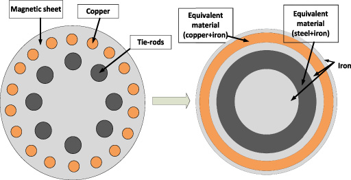
Transformation of the real HSIM rotor geometry to an equivalent multi-layer rotor.
Using the isotropic linear elasticity law and assuming small disturbances, the expression of stresses in the three directions of space can then take the form of:
By then applying the fundamental principle of the dynamics (6), we obtain the PDE (7), whose solution can be put in the general form (8) in each layer (k), going from 1 to N, of the model.
In order to obtain the evolution of the stresses in the rotor it will then be necessary to identify the unknowns of (8) using the following boundary conditions at the borders of the different layers:
By simulating a multi-layer rotor composed of 5 layers respectively iron, steel, iron, copper and iron on a FE software dedicated to mechanical calculation (ABAQUS), it is shown that results from analytical model suits well the FE ones with less than 6% of error (Fig. 8).

Evolution of Von-Misses stress in a 5 layers rotor at 40 krpm.
For a high mechanical sizing of a HSIM it is necessary to know the stresses in each part of the rotor, which is not usually realized from analytical models and uses finite element methods as there is no orthoradial symmetry in its rotor. The objective now is to study whether the developed multilayer model can be applied to the HSIM by adjusting the mechanical properties of each layer so that they are as close as possible to the HSIM rotor.
It turns out that the simulation of the analytical model for the case of a sheet of HSIM transformed into a multilayer rotor reveals a maximum Von-Misses stress that is a little bit higher (9.6%) to the one obtained during the simulation by FE of the true sheet geometry (Fig. 9). Beyond this difference in stress value it is interesting to see that this is mostly consistent with the modelling set up. In fact, the layer where there was previously the rotor cage was replaced by an equivalent layer whose mechanical properties includes a significant proportion of iron. Therefore, the overall stress will be greater than in the real case.
Evolution of Von-Misses stress in a portion of HSIM rotor (Abaqus).
To determine the correct number of tie-rods as well as their required cross section (in cyan in Fig. 10), an optimization process is set. The objective is to ensure a level of pressure P
obj
on the sheets with constraints on the dimensions of the tie-rods so that they do not alter the circulation of the flux (Fig. 11). The mechanical operating point must be kept within the elastic range of 𝜎(𝜀) (stress versus strain) curve. The axial pressure exerted thanks to the tie-roes can be expressed as following:
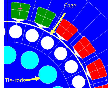
Sectional view of an HSIM.
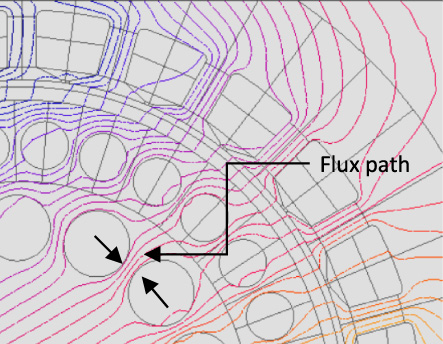
Sectional view of an HSIM with the path of the flux lines.
When dealing with high-speed machines it is important to lead a vibration analysis in order to make sure that the working point of the machine is far enough from some critical bending modes or more globally to define the additional geometrical requirements of the rotor such as the shaft and the bearings for example [8].
A system composed of two bearings, one rigid shaft and a rotor is rotating at a speed 𝜔 (Fig. 12). The distances between the center of the rotor and the bearings are a and b, the total mass of the system is noted m, as well as the total polar and diametral moments of inertia noted respectively I p and I d . In order to develop a 4 degrees of freedom (DoF) system, the bearings stiffnesses are characterized in the x and y directions (kx1, ky1 for the first bearing and kx2, ky2 for the second one). u, v, 𝜃 and 𝜓 are the DoFs and correspond respectively to the displacements and rotations in and around the x and y direction.
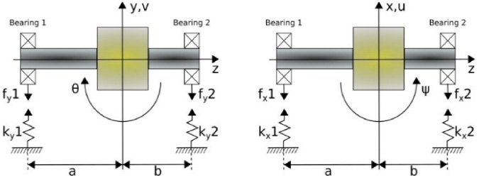
Schematic representation of the system under study.
By expressing the total kinetic and potential energy C and V as a function of the system parameters and the DoF including gyroscopic effects, it is possible to write the Euler–Lagrange equation with q defining each DoF and L = C − V.
Yields to:
The eigenvalue resolution of the previous system leads to evaluation of the critical speeds. For a 4 DoFs system, 8 eigenvalues are to be solved where each pair of conjugate roots is one natural frequency with either forward (FW) or backward (BW) orbit mode shape relative to the rotor spin. It is then possible to draw the Campbell diagram by changing the speed of rotation of the system to clearly identify the critical speeds of operation.
The same model is done with a finite element software (ABAQUS) by implementing springs to simulate the stiffnesses of the bearings in the two directions (Fig. 13). The analytical resolution of the model for a set of parameters leads to the Campbell diagram in Fig. 14. The same parameters of the models are simulated with ABAQUS and leads to results that allows to validate the analytical model as there are less than 1% of error:
An analytical model of an induction machine with a buried cage has been set up by adapting in particular the calculation of the rotor slot leakage inductances. This model is looped back with the mechanical study in order to provide an initial dimension of the bar cross-section. This will subsequently constitute the starting point for all mechanical sizing. Current densities in the windings will be set at 7.5 A⋅mm−2 so that the optimized designs of the machine do not overpass 160 °C at nominal conditions with conventional air-cooling methods (10 W⋅m−2⋅ K−1).
Numerical modeling in Abaqus.
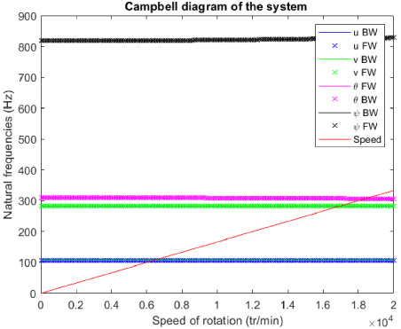
Campbell diagram for the validation system case.
In addition, the coexistence of the cage bars with the tie-rods leads to a coupled sizing whose objective is to satisfy the following criteria: total section of copper to avoid excessive current density. total cross-section of the tie rods for mechanical retention. section of the rotor iron to avoid excessive magnetic saturation.
The chosen design variables are defined by the
When running the magnetic model, the parameters related to the stator are set constant and equal to those presented previously and only parameters related to the rotor will be chosen as design variables and thus will change depending on the objectives set. A first problem with weak coupling is considered by making the copper bar cross-section parameter constant while running an optimization process on the mechanical model of the machine. Indeed, by doing so, the magnetic and the mechanical models are separated and solved one after the other assuming that only one of the two physics involved has an important impact on the other.
In this case, the objective is to minimize the rotor mass under restrictions on the inertial forces in the rotor and the tie-rods sizing. Its mathematical form is then:
This problem is a Mixed Integer Non-Linear Program (MINLP) dealing with both integer and real variables. To solve it, a methodology based on two sequential resolutions is applied. First, we solve the complete problem with a Genetic Algorithm (GA) able to handle mixed variables. The solution found by the GA is then used as a starting point for a Sequential Quadratic Programming algorithm (SQP) dealing with a reduced problem in which the integer variable (Nb tierods ) is fixed to the value found by the GA. The idea is to use both the wide exploration nature of a metaheuristic method as GA, and the effectiveness of a local deterministic method as SQP.
The results of this design process with weak coupling are shown in Fig. 15. The resolution is fast as it took 10 sec and only 245 evaluations were made. However, the results issued from this weak coupling design process do not allow to obtain a machine that will produce the required power as the output torque is at its peak at 69 N.m whereas the specifications required above 70 N.m of rated torque. This observation is normal as no electromagnetic restrictions have been set due to the weak coupling. Nevertheless, by observing that the mainly restrictive criteria in the optimization process is highly depending on the copper bar diameters it is possible to rearrange by hand the design process to obtain the required output torque. Indeed, by reducing the copper bar diameter the mechanical problem is less constrained and the external radius can be increased leading to a higher output torque.
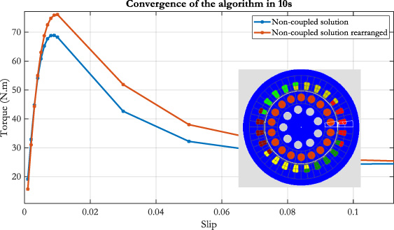
Results of the magneto-machanical design with weak coupled optimization.
Thus, another design process is developed to avoid the manual step by implementing a strong coupling between the electromagnetic and mechanical aspects. Now, the copper bar section S
CB
is set as a design variable leading to a new restriction regarding the output torque T
output
. By doing this, both of the physics will be run at each evaluation and thus will try to lead to a design that complete all the restrictions. Then the design variables vector is then:
The same methodology is used to solve this new MINLP problem. The time before convergence to the optimal solution is now 196 sec with 2575 evaluations of the objective function. Even if the resolution time is longer than the weak coupled optimization process, it remains really fats with basic computing resources.
The solution proposed, illustrated in Fig. 16 responds to all the restrictions criteria thus including the value on the output torque. Looking more precisely to the new design, one can observe that the copper bar section has been reduced to allow a larger rotor regarding to inertial forces restrictions which has been done in the previous design process manually. This also lead to reduce saturation between the copper bars and thus a better magnetic design.

Results of the magneto-machanical design with strong coupled optimization.
Results of the magneto-machanical design with strong coupled optimization.
Moreover, the number of tie-rods is reduced and lead to an increase of their section to maintain the axial pressure applied on the laminated sheets of the rotor while remaining in the elasticity area of the tie-rods made-up with stainless iron.
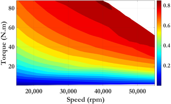
An efficiency map of the optimized design allows to characterize the behavior of the machine along an extended range of speeds of rotation (Fig. 17). The machine control is done with a classical approach consisting in a supply with a constant ratio between the voltage source and the frequency. It can be shown that the corner speed is reached at 40 krpm then the defluxing of the machine starts in order to be able to continue the operation until 60 krpm. The illustrated efficiency map does not consider mechanical losses. However, it shows that the proposed machine is well design as the nominal characteristic are within the higher efficiency region. One should notice that this efficiency map is not the best for this type of electrical machine. Indeed, the presented one is issued from the optimization procedure targeting a nominal speed of 40 krpm. Thus, if changing this, the optimal design will change leading to another efficiency map which can reach in turn better efficiencies for certain rotational velocity.
This study presented an opportunity to establish a multiphysics problem by assembling fundamental components of analytical models, which were coupled to easily get good results and facilitate the implementation of optimization techniques. The need of a strong coupling between the physics has been demonstrated because of the high influence of the parameters on both physics. As the work is essentially focused on high-speed restrictions, only the rotor was first implemented in the optimization process. The stator winding, and yokes have not yet been optimized and can represent a perspective of this work. Moreover, thermal aspects have not been presented in this study but are important aspects to deal with especially in the case of an induction machine. Finally, this research enables an assessment of the viability of an innovative high-speed machine design for onboard electricity generation in future hybrid electric aircraft. In fact, the results shown allows to identify a design of an induction machine which produces 300 kW of continuous power at 40 krpm but a detailed design considering thermal aspects with their impact on magnetic and electrical properties of materials and a further study of high frequency losses needs to be implemented to validate this new topology.
Footnotes
Acknowledgements
The authors have no acknowledgments.