
Abstract
Toroidal transformers are designed using a circular core instead of the traditional laminated rectangular core, which reduces inductance losses and increases efficiency. The primary goal of this study is to understand the cooling mechanisms involved in electrical transformers, which are critical components in power systems. Steady electromagnetic, fluid flow and temperature equations are simultaneously solved (direct method) using the finite elements method FEM of a shielded toroidal transformer. The paper focuses on creating a direct-coupled model (DCM) to understand the processes involved in electrical transformers cooling, using Magneto-AeroDynamic (MAD) models. The nonlinear models developed will be implemented and validated in this parametric study for different inlet velocities and the number of outlet. Transformers generate heat during operation, and it’s important to control the temperature to prevent overheating and ensure reliable operation.
Introduction
Despite the significant progress made in electrical systems, there are still challenges that need to be addressed, such as efficient transport of electrical charge (dissipation) and effective cooling to prevent overheating [1–3]. Numerical simulations can provide a deeper understanding of the behavior of toroidal transformers, including the effect of the magnetic field on the electric field fluid flow, and the heat transfer in response to changes in the magnetic field. These simulations can help to optimize the design of toroidal transformers for specific applications, taking into account factors such as size, efficiency, and electromagnetic compatibility [4].
For a given class of insulation, the temperature of the hot spot limits the power of the device. It is therefore important to evaluate this temperature as precisely as possible and therefore to study the cooling modes involved [5]. Toroidal transformers are highly valued for their use in sensitive and critical electronic circuits due to their many advantages over traditional transformers. Their circular shape and tight windings result in high efficiency and minimal heat generation, making them ideal for use in applications where reliability and stability are important. Additionally, the reduced size and quiet operation of toroidal transformers make them well-suited for use in environments where space is limited and noise levels need to be kept to a minimum. These features make toroidal transformers an attractive choice for a wide range of applications, including medical equipment, audio and video systems, and control systems. A higher current density in the windings is allowed because they use the entire core as a heat exchange surface [4–6].
Forced air cooling systems are widely used in many types of electronic devices, including power systems, audio systems, control equipment, inverters, and more. These systems help to regulate the temperature of electronic components and ensure that they operate within safe temperature limits, which helps to extend their lifespan and improve reliability [5–7].
The primary objective of this study (MAD models) is to understand the cooling mechanisms involved in electrical transformers, which are critical components in power systems. Transformers generate heat during operation, and it’s important to control the temperature to prevent overheating and ensure reliable operation. These developed models are solved using finite element models (electromagnetic, aerodynamic and thermal).
The models can be used to optimize the design of the transformers and to predict their performance under various operating conditions. In this article, we are referring to present the results of simulations performed using the COMSOL Multiphysics software and a magneto-aerodynamic (MAD) model to study the cooling of a toroidal transformer fed at low voltage and cooled by forced air. By using a direct resolution of the MAD model in conjunction with COMSOL, we could study the behavior of the magnetic fields and fluid flow in the transformer, and evaluate the effectiveness of the forced air-cooling system. These strong models are nonlinear because of the variation of physical properties (mass density, heat capacity) as a function of temperature.
Geometry and physics of the shielded toroidal transformer used
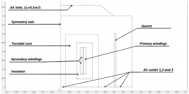
In this case, the toroidal core transformer is a low voltage (LV) system cooled by forced air. This transformer is composed of a torus-shaped magnetic circuit made of ferrite, a Mylar insulator, a copper coil in primary with a supply voltage of 230 V and two secondary outputs of 12 V, all surrounded by a quartz box.
An ideal coil is evenly distributed around the circumference of the ring. This geometry distributes the magnetic field in a complete loop and thus keeps most of the field within the core material [8,10]. The symmetry of revolution is a common property of many devices, including electrical transformers, which have a cylindrical or toroidal shape. In these cases, the geometry of the device can be reduced from a full three-dimensional model to a two-dimensional model by exploiting this symmetry property. The air flow in the toroidal core transformer is introduced by a ventilation system with a velocity flow of 0.5 m/s. The air flow is directed into the transformer to cool it, and then exits through three outlets located below the transformer, as shown in Fig. 1.
Geometry of axismetric model used.
The geometry of this model is based on a circular ring, the coil is wrapped around the central hole of the ring and the outer area. An even distribution of the ideal coil is achieved along the circumference of the ring. This geometric configuration allows the magnetic field to be distributed continuously, keeping most of the field inside the core material. The electrical characteristics of the transformer used are presented in Table 1. The Table 2 presents the electrical and physical properties of the transformer used.
Electrical characteristics of the transformer used
Electrical and physical properties of the transformer used
The 2D mesh model of the toroidal core transformer was obtained using the COMSOL Multiphysics software and the axisymmetric finite elements method is presented in Fig. 2.

Mesh of the model used.
In what follows, we present the mathematical formulations modeling the cooled electrical system (transformers), which express the coupled phenomena. Electromagnetism (Maxwell’s equations) and aerodynamics (Navier--Stokes’ equations), as well as some simplifying assumptions [9,11].
Maxwell equations
Maxwell’s equations, also known as Maxwell–Lorentz equations, describe the behavior of electromagnetic fields in a vacuum and form the basis of classical electromagnetism. The equations are a set of four partial differential equations that relate the electric and magnetic fields to their sources. The equations describe how the electric and magnetic fields interact with each other and how they are produced and influenced by electric charges and currents. They constitute the basic postulates of electromagnetism, with the expression of the electromagnetic force of Lorentz.

The MAD nonlinear coupling diagram.

Contour of magnetic potential norm [Wb/m].
Magnetic flux density [T].
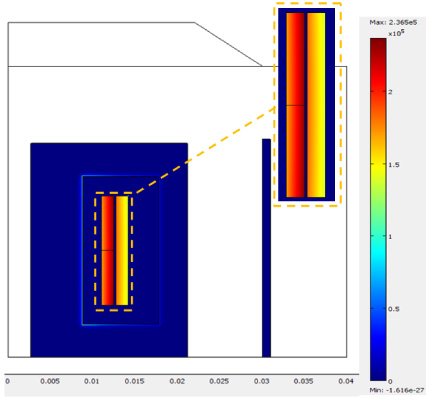
Resistive heating, time average [W/m3].
Temperature distribution without inlet velocity (U0 = 0 m/s).

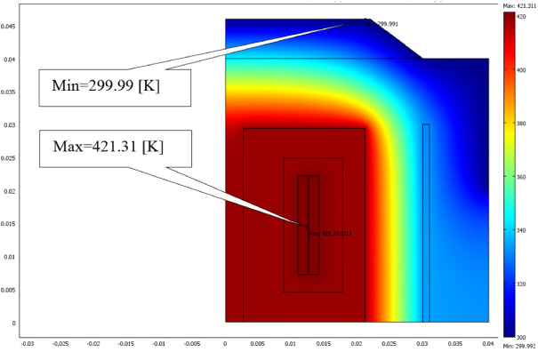
Temperature distribution with air inlet velocity field (U0 = 0.5 m/s).

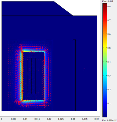
Velocity field [m/s] and convective heat flux [W/m2].

Heat flux by conduction [W/m2].
Temperature distribution [°K] (two outputs).
Velocity field [m/s].
Heat flux by conduction [W/m2].
(a,b): Velocity and convective flux at the transformer outputs.
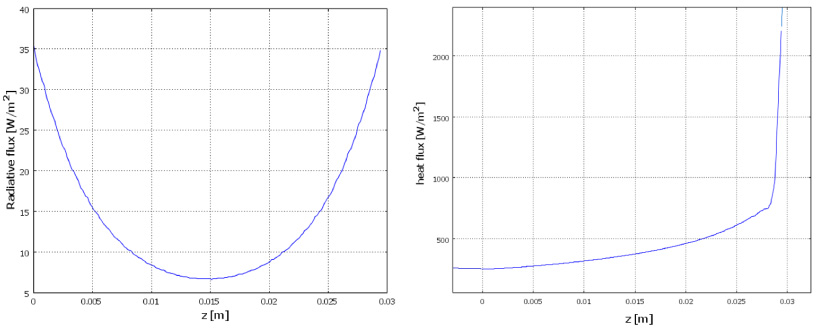
(c,d): Radiation flux and Heat flow in the axial face of the core.

Convective heat flux [W/m2].

Cell Reynolds number.
Cell Peclet number of the model used.
Variation of temperature as a function of speed at the axial outlet [k].

Variation of temperature as a function of speed at the intermediate outlet [k].
Velocity field as a function of the velocity at the intermediate outlet [m/s].
Heat flow as a function of velocity at the intermediate outlet [W/m2].
Maxwell–Faraday:
Maxwell–Ampère:
Magnetic flux conservation equation:
Maxwell–Gauss:
H: Magnetic field intensity (A⋅m−1), B: Magnetic induction (T), E: Electric field (V⋅m−1), J: Current density (A⋅m−2),
There are two categories of formulations based either on the electric field E, or on the magnetic field H, in particular the potential A-V formulation is the most used and the most general described in the following equation:
The Navier–Stokes equations are a set of partial differential equations that describe the motion of fluids and can be considered as Newton’s second law applied to fluid motion. In the case of a Newtonian fluid, we obtain:
𝜏: is the viscous stress tensor, 𝜌: density of the fluid [Kg/m3], F : force density [N/m3], 𝜂: dynamic viscosity of the fluid [Kg/m⋅s] and p : is the pressure [Pa].
The resistivity 𝜌 of a conductive material is involved in the calculation of the resistances and varies linearly for low to moderate temperatures:
Energy assessment equation of heat diffusion:
Where:
The MAD is a current approximation that considers a single medium fluid for all particulate environments. In our applications (cooled electrical systems such as: transformers, machines), the fundamental equations of the MAD that we will use thereafter consist of the electromagnetic equations written in magnetic vector potential and electric scalar (A–V) and conservation equations that we have presented previously (Eqs (6)–(8)) [9–13]. This figure (Fig. 3) shows the interactions between the studied phenomena.
To solve the partial differential equations (PDE) of the previous phenomena we used the FEM finite element method with the COMSOL Multiphysics software which allows these MAD phenomena to be coupled and resolved simultaneously (strong coupling mode).
Leads to a unique system of equations with an unknown [I] with five components: A, T, vr, vz and p.
The finite element method (FEM) is a numerical technique that is widely used to solve partial differential equations, such as those governing the interactions between the electromagnetic (EM) field and fluid in the MAD model. COMSOL Multiphysics is a powerful simulation software that allows to correlate and simulate different physical phenomena in a single model. We used the FEM method in combination with COMSOL Multiphysics, to solve equations that describe the behavior of a system, taking into account the interactions between different phenomena.
The ability to couple and simulate multiple physical phenomena in a single model makes it an ideal tool for studying complex systems such as electrical transformers.
Electromagnetic study
This study aims to evaluate the electromagnetic quantities described previously using the model based on the magnetic vector potential and the electric scalar field (A-V formulation).
Figure 4 highlights the contour lines of magnetic potential vector at the primary and secondary windings. On the other hand, it is excluded towards the axis and outside the magnetic circuit. The Fig. 5 shows that the magnetic flux density is higher in the ferromagnetic core, which is attributable to the presence of a very high magnetic permeability of the ferromagnetic material used. This observation demonstrates the ability of the ferromagnetic material to effectively concentrate and guide the magnetic flux through this type of shielded toroidal transformer. The Fig. 6 represent the resistive heating. We see that the power density by Joule effect is important in the coils and more concentrated in the secondary windings due to the concentration of induced currents in this region.
This study allowed us to better understand the electromagnetic behavior in the shielded toroidal transformer and appreciate the zones where the electromagnetic quantities are more intense and where are excluded, which is crucial to optimize the design and performance of the transformer.
Thermodynamic study
Thermodynamic study of forced air-cooling involves analyzing the behavior of air as it moves through a cooling system. The number of exits and speed of entry of air plays a crucial role in determining the efficiency of the cooling system.
(a) Study with three evacuation exits: The comparison of Figs 7 and 8 allows us to study the effect of air speed on cooling. By comparing the two figures, we can observe how changes in air speed can impact the cooling performance of the system. The first figure (Fig. 7) represents the temperature distribution without ventilated air inlet velocity, while the second (Fig. 8) shows the effect of the inlet air flow towards the three outlets of evacuation, on the amplitude.
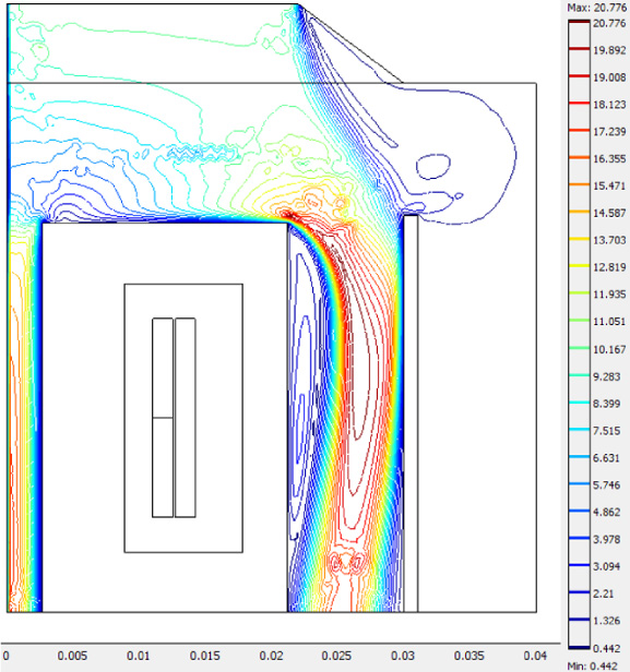
Through Fig. 9, we clearly notice the effect of convection on transformer cooling in the region where the velocity field is large and where the convective heat flux is very high.
Figure 9 also registers an important physical aspect in the mechanics of the compressible fluid of air recirculation in the region above the side exit. On the other hand, the heat flux by conduction Fig. 10 is high in the electric and magnetic circuit and is low in the other regions (air and insulation) due to their low thermal conductivities.
(b) Study with two evacuation exits: For technological reasons of robustness (not to pierce the transformer support much) in this part by closing the third side exit (exit 3, see Fig. 1) and keeping the two exits (axial and intermediate) with the same air speed U0 = 0.5 m/s in the inlet. After calculation, we found the following results:
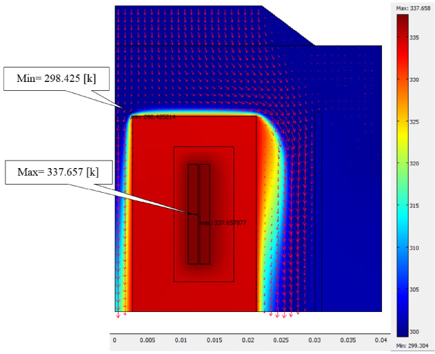
We observe in Fig. 11 a significant reduction in temperature, with a maximum of 337 °C, in comparison to what was observed in Fig. 8 for three evacuation exits (maximum 343 °K). This outcome demonstrates the enhancement of the velocity field in the axial and intermediate zones of the transformer, where the presence of the heat source is significant.
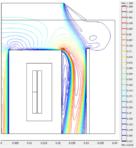
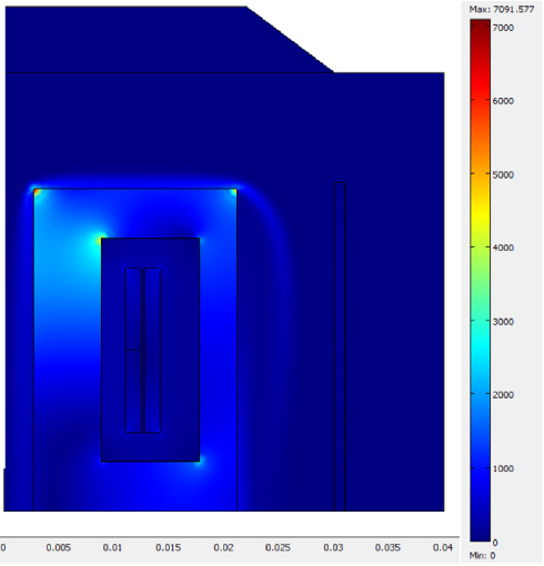
In Fig. 12, we can see a circulatory movement on the right within the enclosure, attributed to the closed outlet at the bottom, and a free laminar flow due to the velocity field in the two other axial and intermediate outlets (see Fig. 14). As for Fig. 13, we notice that the heat flux by conduction is high in the electrical and magnetic circuit, especially at the edge.
Figure 15(c,d) represents the radiation flux and the heat flux on the axial face of the core. It can be noted that the radiation flux can reach almost 10% of the total flux generated by the axial face of the core. By comparing Fig. 16 with Fig. 9, we clearly notice the difference in the convective heat flux between case a (three evacuation exits) and case b (two evacuation exits).
In Fig. 17, we can observe that the maximum Reynolds number is less than 2000, indicating the laminar nature of the flow. The Reynolds number expresses the ratio between inertial forces and viscosity forces that occur during fluid flow [13,14]. The Peclet number is a dimensionless value used to describe the relative importance of advective and diffusive transport in various physical and engineering systems. It is defined as the ratio of advective transport to diffusive transport and is commonly applied in fields such as heat transfer, mass transfer, and fluid dynamics. The Peclet number offers valuable insight into the transport behavior of a system and is useful for predicting the onset of instability and determining the rate of mixing or transport. This number is used in heat transfer and mass transfer, representing the ratio of transfer by forced convection to transport by diffusion (thermal or mass) [15]. The following figure, Fig. 18, demonstrates that the flow is predominantly of a convective thermal nature because this number is very large (>1) across almost the entire flow study domain.
Parametric study according to the input speed
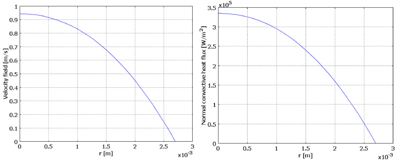
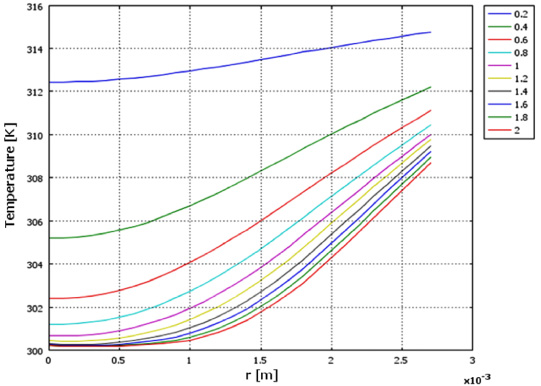
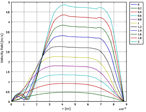
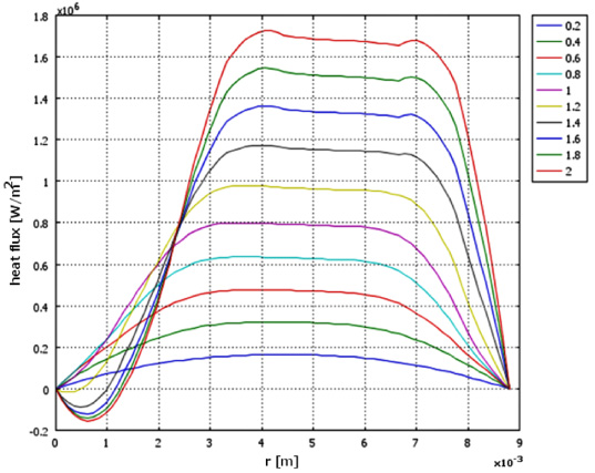
This part is dedicated to a parametric study concerning the forced air velocity, which varies between U0 = 0.2 m/s and U0 = 2 [m/s]. Initially, we present in (Fig. 19) and (Fig. 20) the variation of temperature at the axial and intermediate outlets for different velocity values. It’s important to note that the heat flux, as shown in (Fig. 21), follows the velocity field displayed in (Fig. 22) at the axial outlet, increasing with the forced air inlet velocity.
On the other hand, we observe that at the intermediate outlet, the temperature undergoes an exponential decrease due to the expansion (recirculation) of the air in the outlet, occurring within a few millimeters of the toric core. This trend corresponds to the variation of the velocity field and the heat flux, as depicted successively.
When closely examining the curves of the heat flux and the velocity field (see Figs 21 and 22), the phenomenon of cascade effects becomes evident, particularly in the velocity range from 1.2 to 2 [W/m2] and from 1.4 to 2 [m/s] respectively.
Conclusion
Magneto-aerodynamics (MAD) is a field of study that involves the interaction between a magnetic field and fluid flow. The equations used to describe the phenomena in MAD are a combination of hydrodynamic equations and Maxwell’s equations, which describe the behavior of fluids and electromagnetic fields, respectively.
The model developed in this study focuses on three axes: the electromagnetic study, the thermodynamic study, and finally the parametric study according to the input speed and the output number. Exposure to these axes makes it easier to understand electromagnetic behavior in more detail, and how airflow, velocity, and air exhaust outlet configurations can affect the shielded toroidal transformer’s performance.
The axisymmetric MAD model described is designed to capture the evolution of various quantities such as electromagnetic, thermal, and flow properties within cooled transformers. The modeling results can provide important insights into various phenomena such as induction, Joule heating and the effect of cooling fluid velocity on temperature decrease. These findings are indeed important for industrial-scale applications, as they can help to optimize the design and performance of cooled transformers. By developing a mathematical model of MAD that describes the interaction between the electromagnetic field and fluid in motion within the limit of laminar flow, the objective of the work is achieved. This model can serve as a valuable tool for engineers and researchers to better understand and predict the behavior of cooled transformers in real-world applications.
This model can be solved using a variety of methods, such as the finite element method, the boundary element method, or the volume integral equation method. In our work, we have chosen to use the FEM as the direct method for solving the MAD model. The FEM is a powerful and flexible technique that can handle complex geometries and boundary conditions, making it well-suited for MAD simulations.
Footnotes
Acknowledgements
This work was supported by the MOHAMED SEDDIK BEN YAHIA University, Jijel-Algeria, under Project: PRFU-2023 Code: A01L07UN180120230006.