
Abstract
The critical speed of eddy current braking is a vital parameter in the design of eddy current braking devices. Currently, most simulations and experiments are used to determine the critical speed, which means a lot of time costs. This paper presents two laws of critical speed variation to help designers more quickly determine the critical speed of a particular eddy current braking device. At first, the structure and the critical speed principle of permanent magnet rotary eddy current brake (PMRECB) are described. Secondly, the finite element analysis is used to verify the accuracy of the two laws. Finally, the validity of the finite element model is confirmed by the eddy current braking test.
Keywords
Introduction
Based on Faraday’s law of electromagnetic induction, the eddy current will be induced, when there is relative motion between the conductor plate and the magnetic field. The induced eddy currents will generate braking force, with the advantages of no mechanical contact and high reliability [1]. Thus, eddy current brakes have been used in a lot of industrial applications, including the high-speed rail transit field, automotive brakes field, and high rotation speed braking field [2–9].
The numerical value of the eddy current braking force is one of the most important design parameters of an eddy current braking device, which is directly associated with the moving speed of the conductor in the magnetic field [10–16]. Due to the interference of the induced eddy currents with the original magnetic field, the eddy current braking force tends to increase and then decrease along with the speed. The maximum braking force is the peak value of eddy current braking, and its corresponding speed is called the critical speed, a vital parameter for eddy current brakes.
Studies on the critical speed of eddy current braking can be found in a lot of papers. Cho et al. [17] designed a drum-type eddy current brake. The braking force generated was analyzed and calculated. The experimental results show that the critical speed of eddy current braking shows a certain relationship with the material and thickness of the coating. The critical speed will be decreased by increasing the electrical conductivity or thickness of the coating material. The experimental values are compared with the calculated values and simulation results, showing good accordance. Li et al. [18] proposed a novel permanent magnet linear eddy current brake. The eddy current braking force can be adjusted by moving the magnetic field adjusting plate laterally. Both experimental and analytical results suggest that the critical speed of eddy current braking is related to the area covered by the magnetic field. It indicates the changing law is the larger the area of the conductor plate covered by the magnetic field, the smaller the eddy current braking critical speed. Li et al. [19] designed and built a rail ECB test system, and the braking characteristics were tested. The eddy current braking force of the train at different working conditions is explored. The result demonstrates that critical speeds are not the same for the two working conditions. Additionally, Yazdanpanah et al. [20] and Kou et al. [21] also investigated the eddy current braking critical speed and found that the critical speed was related to the thickness of the conductor material and the excitation mode respectively.
Based on the previous studies, the conductivity, the thickness of the conductor layer, the magnetic field coverage area, the working condition, and the excitation mode can influence the critical speed of the eddy current brakes. However, the key design issues including the effect of the size of the eddy current braking device on the critical speed, and the numerical relationship between the conductivity of the conductor plate and the critical speed have not been investigated. This results in more difficulty in quickly determining critical speed during the design of eddy current braking devices. Therefore, it is necessary to explore the above issues. In this paper, the dimensional parameters (0.5, 0.75, 1, 1.25, 1.5 multiples) of the PMRECB and the conductivity (11, 38, 60 MS/m) of the conductor plate are selected as the variables to facilitate the adjustment of the geometric parameters and highlight the change law of critical rotational speed.
The rest of this paper is organized as follows: Section 2 explains the structure and working principle of the permanent magnet rotary eddy current brake (PMRECB). In Section 3, the critical speed principle of the PMRECB is analyzed. The finite element analysis validation for the PMRECB is presented in Section 4. In Section 5, the experimental device is designed and manufactured. The experiments on the change of eddy current braking torque peak value are performed. Finally, the conclusions are summarized in Section 6.
Structure of the PMRECB
The structure of PMRECB includes primary and secondary. In the primary, axially magnetized permanent magnets alternating in their direction of magnetization, are placed on the surface of the magnetic yoke, which is made of the high permeability soft iron. There are two kinds of secondary structures; one is the mainstream composite structure composed of conductor plate and back iron [22–24], and the other is only a simplified single conductor plate [25,26]. The finite element simulation results of the two structures were compared in this study, and it was found that the gap between them was very small. Both of them conform to the critical rotational speed variation law of PMRECB proposed in this study. Therefore, the simplified structure displayed in Fig. 1(a) is used for simulation and experiments to simplify the calculation and finite element simulation. For ease of experimentation, permanent magnets are designed as shown in Fig. 1(b).

(a) The simplified structure of the PMRECB. (b) The complete structure.
Firstly, the principle of eddy current peak value and critical speed is explained. According to the laws of electromagnetic induction, with the increase of the relative rotation speed of the primary and secondary, the eddy current density on the secondary conductor plate tends to gradually increase. In addition, because the magnetic field of the permanent magnet interacts with the induced magnetic field of the eddy current, the eddy current braking torque increases. However, the increase is not infinite. The induced magnetic field generated by the eddy currents will exert a demagnetizing effect on the magnetic field of the permanent magnet. When both magnetic field strengths are approximately equal, the peak value of eddy current braking torque occurs. Therefore, the critical speed at the peak value of the eddy current braking torque can be explored by the eddy current magnetic induction strength.
Using finite element simulation, the magnetic field line distribution under the two motion conditions is shown in Fig. 2. Figure 2(a) shows the distribution of magnetic field lines with no relative motion between the primary and secondary. With the rotational speed being 5000 rpm, the combined magnetic field line of the induced magnetic field and permanent magnet magnetic field is shown in Fig. 2(b). It can be observed from Fig. 2, that when the primary and secondary move relative to each other, the demagnetization effect of the eddy current magnetic field can distort magnetic field lines. Meanwhile, the secondary magnetic density will increase in the direction away from the rotational speed. The induced magnetic field of the eddy current can be divided into components in the following two directions: axial and circumferential components. The circumferential component magnetic field cannot produce eddy current braking torque. Thus, axial components are mainly taken into consideration.
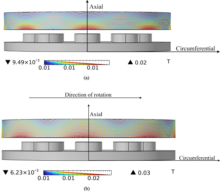
(a) Magnetic field without relative motion. (b) Synthetic magnetic field distribution at 5000 rpm.
According to the 3-D structure of the PMRECB and the distribution of magnetic lines in Fig. 1 and Fig. 2, respectively, the 2-D model of the PMRECB is displayed in Fig. 3.

PMRECB 2-D structure.
The actual magnetic field distribution is very complex. The following assumptions are made to simplify the theoretical analysis: Air gap and magnetic leakage of non-magnetic materials and the hysteresis effect are not considered. The impact of temperature on the magnetic permeability and conductivity of electromagnetic materials is not taken into account. The axial components of the eddy current magnetic field are evenly distributed in the air gap and the secondary. The variation of the static operating point of the permanent magnet is not considered.
The magnetic field strength inside the magnetic yoke and back iron is zero. Therefore, the Ampere-loop theorem is employed to calculate the eddy current magnetic field:
The depth of eddy currents skin effect can be calculated by Eq. (4):
Based on the definition of skin depth, the eddy current density of the secondary after considering the skin effect can be calculated by Eq. (5):
During the process of eddy current braking, the magnetic field induced by eddy current on the secondary is not uniform, and its demagnetization effect on the permanent magnet is difficult to characterize by magnetic Reynolds number. Therefore, in this study, a new magnetic Reynolds number (R
n
) proposed by Li et al. [27,28] in the field of electromagnetic damping research is adopted for describing the strength of the eddy current demagnetization effect of PMRECB. This modeling strategy can significantly simplify the process of determining the critical rotational speed in PMRECB simulation and experiment, and preliminarily deduce the variation trend of the critical rotational speed as the conductivity of the conductor plate and the size of the PMRECB change. The specific calculation is provided in Eq. (6).
It can be assumed that the area of the eddy current region is not affected by rotational speed changes. From a macro perspective, R n increases in proportion to the rotational speed. When the PMRECB speed gradually increases from 0, the demagnetization effect of the induced eddy current will decrease the air gap flux density, and R n will increase from 0 to positive infinity. During this process, when R n is approximately equal to 1, the demagnetizing effect of the induced eddy current magnetic field cannot be counteracted, and braking torque reaches its peak value. The rotational speed at this time is the critical speed of PMRECB.
The eddy current braking torque critical rotational speed can be calculated by Eq. (7):
From Eq. (7), in the case of constant 𝛿 ag and T cp , the critical rotational speed is only associated with the conductivity of the secondary 𝜎, the area of the eddy current region S, and the eddy current skin effect. When the conductivity of the conductor plate 𝜎 increases from 38 MS/m to 60 MS/m, the critical speed will decrease by approximately 36.7%. With the increasing size of PMRECB, the eddy current area S and rotational radius r increase from 100 mm2 and 30 mm to 200 mm2 and 60 mm, respectively, and the critical speed will decrease by around 75%. Moreover, in line with Eq. (4), when the rotational speed is 700 rpm and the material of the conductor plate is copper, the skin depth is about 9.55 mm. If the thickness of the conductor plate exceeds the skin depth at this rotational speed, for example, the thickness of the conductor plate is 10 mm, the denominator of Eq. (7) will be reduced by this effect, which can increase the critical rotational speed.

The 1× PMRECB 3D FEM modeling.
Parameters of 1× PMRECB
Different parameters for different multiples of PMRECB
Finite element modeling
In the current section, COMSOL Multiphysics 6.0 software is used to demonstrate the accuracy of the above laws by the 3-D eddy current electromagnetic finite element method. As demonstrated in Fig. 4, the finite element meshing of 1× PMRECB contains 121108 mesh vertices. The grade of permanent magnet is all N35 and the residual flux density is around 1.21 T. Due to the magnetic field distribution will be disturbed by hysteresis greatly, hysteresis is still not considered in FEM simulations. The 1× design parameters of the PMRECB are shown in Table 1. Table 2 presents the different parameters of PMRECB of different multiples, whose diameter is multiplicative to the 1× PMRECB.
Analysis of results
Figure 5 shows the distribution of eddy current density on the secondary conductor plate at 400 rpm, which is calculated by 3-D FEM. Based on Fig. 5(a) and (b), the eddy current density on the secondary conductor plate of the large PMRECB is significantly higher and the eddy currents are significantly more aggregated, with both devices being at the same rotational speed. The demagnetization effect will be significantly enhanced by the increase in eddy current density and aggregation, which will accelerate the growth of the R n . In addition, the eddy current braking torque critical rotational speed will also be smaller. Moreover, Fig. 5(c) shows the eddy current density in the low-conductivity conductor plates (38 MS/m), which is smaller than the eddy current density in a high-conductivity conductor plate. The conductivity exerts a great influence on the eddy current loss. Therefore, the magnitude and growth rate of the eddy current braking torque is decreased, resulting in an increase in the critical rotational speed of PMRECB.

(a) Eddy current density distribution for the 0.75× PMRECB. (b) Eddy current density distribution for the 1× PMRECB. (c) Eddy current density distribution for the 1× PMRECB of low conductivity conductor plate.
Figure 6 shows the relationship between critical rotational speed and PMRECB size multiplier. The finite element analysis results are consistent with the conclusions in Fig. 5(b). With the increasing size multiplier of PMRECB, the eddy current area and rotational radius increased in proportion to the multiplier. Therefore, the critical rotational speed of eddy current braking decreases as the size multiple of PMRECB increases.

Variation of the critical rotational speed of PMRECB with different multiples.
The specific numerical changes in critical rotational speed and secondary conductor plate conductivity are shown in Fig. 7, calculated with the use of the 1× PMRECB model. The finite element analysis results conform to the conclusion from Fig. 5(c). With the decreasing conductivity of the conductor plate, the eddy current density on the conductor plate also decreases. Therefore, the eddy current braking critical rotational speed increases as the conductivity of the conductor plate decreases. Moreover, it can be observed from Fig. 7, that the ratio of the critical rotational speed of PMRECB’s conductor plate with different conductivity is very close to the ratio of the conductivity. Moreover, this law can be applied to estimate the critical rotational speed of PMRECB of the same size using different conductor plate materials.

Critical rotational speed of PMRECB at different conductor plate conductivity.
To confirm the veracity of the two laws, an eddy current braking test bench is manufactured, and the specific structure is displayed in Fig. 8. There is a drive motor, sprocket wheel, tachometric gear, hall sensor, and PMRECB in the test bench. The PMRECB consists of a magnetic yoke, permanent magnets arranged in polar intervals, and a conductor plate made of aluminum. The gear rotation frequency can be detected by the hall sensor. Then the digital frequency signals are transmitted to the PC, which can obtain the conductor plate rotational speed. Subsequently, the braking torque applied to the conductor plate can be calculated from the change in rotational speed. In addition, parameters such as temperature will also have an impact on the critical rotational speed [11,17]. However, since the PMRECB structure used in this paper has good heat dissipation, the influence of temperature and other parameters on the critical rotational speed is ignored in the experiment process.

(a) Eddy current braking test bench. (b) PMRECB permanent magnet arrangement.
The variation data of the braking torque for 0.5× and 1× PMRECB at high conductivity and 1× PMRECB at low conductivity are shown in Fig. 9, respectively, which are derived from the experiment test and FEM. The specific dimensional parameters of the 0.5× and 1× PMRECBs are displayed in Tables 1 and 2. The experimental results of 1× PMRECB have removed the frictional effect of the test bench without eddy current braking. However, owing to the 0.5× PMRECB braking torque being small, it is difficult to measure accurately. Therefore, the braking test results of the 0.5× PMRECB do not remove the friction effect, but add the friction braking torque of the test bench without eddy current braking to the FEM results.

Braking torque variation of the PMRECB.
It can be observed that the eddy current braking torque curve obtained by the FEM is consistent with the experimental test. Therefore, the veracity of the FEM is verified. The 1× PMRECB has a significantly smaller critical speed than the 0.5× PMRECB. The ratio of critical speeds of 1× PMRECBs with different conductivities is extremely close to the ratio of conductivities of their FEMs.
To conclude, in this study, the influence of the size of PMRECB and the conductivity of the conductor plate on the critical speed is investigated. Firstly, the structure of PMRECB is introduced and the critical speed analytical model is built. A new magnetic Reynolds number is employed to explore the mechanism of the critical rotational speed. Secondly, the 3-D FEM is developed. Meanwhile, the influence of the size of PMRECB and the conductivity of the conductor plate on the critical rotational speed is analyzed. The results demonstrate that the increase in the size of PMRECB and the increase in the conductivity of the conductor plate will lead to a decrease in the critical rotational speed. Additionally, the conductivity ratio of the two different materials is very close to the inverse of the respective critical rotational speed. Finally, the two rules are verified on the test bench. The experimental results can demonstrate the correctness of the finite element model and laws. Moreover, this proposed research process can guide the design of PMRECB with high rotational speed and high torque to lower the cost during the design process.
Footnotes
Acknowledgements
This work was supported in part by the National Natural Science Foundation of China (52304177), in part by the Natural Science Foundation of Shandong Province (ZR2021QE183), in part by the China Postdoctoral Science Foundation (2022M721975), and in part by the Natural Science Foundation of Shandong Province (ZR2022QE157).