
Abstract
This article proposes a design of windings for medium-frequency transformers (MFTs) at the heart of high-power Solid-State Transformers (SSTs). With aluminum interleaved foils of the correct thicknesses, it is possible to obtain low winding losses and a very low leakage inductance well adapted to high-power SSTs able to operate in the medium-voltage grid (5–20 kV). The MFT equivalent resistance and leakage inductance are determined using an analytical model based on Dowell’s hypotheses. Several interleaved winding configurations are analyzed and compared to the standard structure made of two concentric foil coils. The experimental validation is made with short-circuit tests of an MFT fed by a low-level square voltage source at several kHz, which can provide the necessary high current.
Keywords
Introduction
The decarbonization of our society imposes progressive changes in the electrical grid structure. In the classical structure, the stability is managed by a limited number of large adjustable power plants connected to the high voltage (HV) grid. The distribution grid (medium and low voltage) is passive. The high global inertia of all the synchronous generators is a natural energy storage that helps the short-term control of the frequency corresponding to the active power. This global inertia gives time for the suitable control of the turbine power. Most renewable sources are connected to the grid by electronic converters that do not bring any equivalent inertia. With an increasing number of such sources, grid stability becomes more challenging [1–3]. Recent scientific articles deal with the stability of isolated grids, including several intermittent renewable sources. They show that a real-time dialogue between the sources, the loads, and the storage systems ensures grid stability. This data is processed by appropriate computer systems connected by communication lines. Advanced artificial intelligence or fuzzy logic techniques [4–6] can be used. The output data of these control systems are used to tune smart nodes, which can control the bidirectional energy flows in real time and are placed at critical points of the densely meshed grid.
High-power Solid-State Transformers (SSTs) can perform this function. The central elements of SSTs are medium or high-frequency transformers [7]. For high-power applications (over 5 MW) operating in the medium-voltage (MV) grid, the standard solution consists of assembling many SST cells of several hundreds of kW in series and parallel [8,9]. The standard designs of the central transformer of such SST cells are based on ferrite or nanocrystalline cores of limited sizes [10,11]. The coils are made with Litz-wire or conducting foils (Cu or Al) [12–14]. With the recent development of power electronic switches [15], the way toward higher power SST cells is open but needs improvement of medium frequency transformers (MFTs). Recent studies show that it is possible to decrease the number of cells in high-power SSTs by increasing the power of each cell. The transformers of such cells can use wound cores made with thin grain-oriented electrical steel (GOES) strips [16,17]. Such GOES cores do not have the size limits of the nanocrystalline ones; however, they have higher specific losses at medium frequencies. The core can operate at high temperatures to limit eddy current losses to limit this drawback. This magnetic material can withstand high temperatures while keeping its magnetic properties [18].
The paper proposes a winding design that offers the low leakage inductances and AC resistances required by high-power SST structures. Before developing the main idea, the paper will remind you of the standard structure of SSTs and GOES wound cores’ performances in this context. Then, the proposed winding structure is described and analyzed using an analytical model. Several solutions are compared. The experimental validation consists of short-circuit tests of an MFT fed by a square low-voltage at the operating frequency. The end of the paper deals with a comparative analysis of several winding solutions. It details the method required for computing the efficiency of the MFT inside the whole SST working at its rated operating point.
Solid-state transformer structure
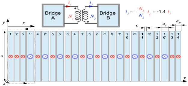
Figure 1 presents the dual active bridge (DAB) structure, which is the heart of high-power SSTs. An AC–DC reversible converter is placed on each side of this heart to transfer the power between two AC grids.

DAB structure connecting the two DC internal busses of high-power SSTs.
The MFTs are placed between two active IGBT bridges. The design of such MFTs involves many choices. The main elements are the core cross-section for the magnetic flux, the operating frequency, and the winding structure. The goal is to provide a good balance between the MFT sizes and the global losses for a given rated power.
The power P transferred between the input and output is controlled by the command angle 𝜑, which creates a time lag 𝜑∕𝜔 between the commands of the two IGBT bridges (𝜔 is the angular frequency). Equation (1) yields the transferred power [19]. v
A
and v
B
are the voltages of the two DC smart grids’ supposed constant, and L
L
is the leakage inductance of the MFT referred to on the primary side.
A previous study shows that GOES wound cores operating at high temperatures can be used to design compact medium-frequency high-power transformers.
Figure 2 presents an experimental curve published in [20] illustrating the reduction of core losses with temperature. It also shows that core losses are lower for rectangular voltages than for sine ones. Compared to a standard solution based on a nanocrystalline core, the higher specific loss of the core is a disadvantage, which must be put into perspective considering several advantages:
A higher stability of the material crystalline structure that limits the aging processes. A higher tolerance to accidental overheating. The GOES material is available in wide strips that allow the design of big wound cores for high-power MFTs at reasonable costs.
The structure of the hot-core transformer avoids any contact between the core and the winding, which is fixed between two mechanical supports over and under the core. The core is also pressed between these mechanical supports using mica plates. Vertical fresh airflows, provided by small fans, make possible the cohabitation of a hot core inside coils at usual temperatures. Accepting reasonably high core temperatures, this transformer can operate at high flux densities up to several kHz, with a specific power and an efficiency in the same range as standard SSTs [21].

Specific core losses in a wound GOES core at 1.2 T–4 kHz. Experimental curve taken from [20].
The paper proposes a winding structure of two interleaved insulated aluminium foils (one for the primary and the other for the secondary). The GOES wound core of the prototype has a mass of 25 kg. The core’s effective cross-section is 53.3 cm2; the window height is 180 mm. The winding can be made with 160 mm width aluminium foils for this core. At 4 kHz, the skin depth in aluminium is 𝛿 = 1.36 mm at 50 °C. Therefore, a 1 mm thick aluminium foil can be a reasonable solution. At this frequency and for a primary square voltage V1 = 1500 V and a 14-turn primary coil (N1 = 14), the flux density in the GOES core is 1.28 TPeak. The magnetizing current is 2.25 A peak. For a 750 kVA transformer, the primary current RMS value is 500 A, and the average current density in the foils is 3.12 Apeak∕mm2. The magnetizing current can be neglected compared to the rated one. The primary and the secondary currents are linked together by (2). They flow in opposite directions.
Interleaved foil winding cross-section inside a core window for N1 = 14 and N2 = 10.
Several decades ago, Dowell studied the electromagnetic behaviour of foil-windings [22]. He developed a 1D analytical model able to compute eddy currents inside the foils for several foil-winding configurations. His model has been confirmed by a more recent numeric study [23]. The paper develops a similar model for interleaved foil-windings. The core imposes a field in the y-direction and a negligible value at its borders. The effects of the rotation of the eddy current lines at the foil ends are also neglected. With these hypotheses, the problem is reduced to 1D: the x-direction. It can be expressed by the diffusion Eq. (3) where H is the y-component of the vector

Axis defined for the considered foil (a = a P or a S ).
The resolution is straightforward using the axis x
′
presented in red in Fig. 4.
An interleaved foil-winding prototype has been built following Fig. 3 (N1 = 14, N2 = 10) and mounted on a GOES wound core. However, for practical reasons, the 10-turn secondary has been made with the same aluminium foil thickness (a P = a S = 1 mm). The average current density in the 10-turn secondary is 1.4 times the current in the primary. Tests must be made at currents lower than the rated current. The foils are insulated by 0.2 mm mylar sheets.
Short-circuit tests have been performed at three frequencies with a square primary low voltage. A small ferrite core transformer of ratio 10/1 has been placed between a standard inverter and the transformer under test. This transformer provides the necessary high currents at low voltages and galvanic insulation allowing a direct connection of the oscilloscope to the primary voltage. Current measurements have been made using a Tektronix A621 precision probe. An oscilloscope records the primary voltage and current instantaneous values with 100,000 points over several periods. Measurements are made at 100 A peak. This relatively low current (1/5 of the rated current) limits the winding temperature increase during experiments. The equivalent resistance and inductance related to the primary side are determined with the first harmonic of the recorded voltage and current, applying the Fourier series in their complex form to the recorded curves. For comparing the experimental results to the prediction of the analytical model, the parameters are adapted to the prototype construction (N1 = 14, N2 = 10, a P = a S = 1 mm, b = 160 mm). Measurements and analytical results are presented in Table 1 for 3 frequencies.
Experimental results and model predictions
Experimental results and model predictions
The leakage inductances calculated with the analytical model are in good agreement with the measurements. However, the higher experimental AC resistances denote the limits of the 1D model applied to a 3D structure. For most applications the accuracy of the leakage inductance is a major parameter required for calculating the variations of the command angle 𝜑 using (1). The estimation of this angle is a basic element for designing the control system. The equivalent resistance influences the global efficiency of the SST, which depends on several other parameters (iron losses, losses in the IGBT bridges). The accuracy of this parameter has a less important role.
This section applies the analytical results of Section 3 to several foil-winding solutions.
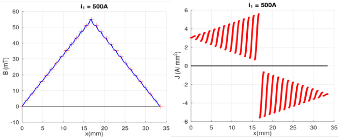
For N1 = N2, the interleaved winding is easy to build because the two identical aluminium foils with their insulation layer are wound together. Figure 5 presents the flux density (left) and the current density (right). The positive current density values correspond to the primary, the negative values to the secondary. For this interleaved winding configuration. The flux density distribution is very regular; the leakage inductance is low (L L = 0.96 μH).

Instantaneous leakage flux density and current density in the whole interleaved winding.
The interleaved foil winding solution is compared with the standard solution using concentric coils presented in Fig. 6. The 14-turn primary coil is wound first using a foil with its insulating layer; then, the secondary 14-turn coil is wound.
Standard foil-winding structure (concentric coils) inside a core window for N1 = N2 = 14.
Instantaneous leakage flux density and current density in the whole winding for N1 = N2 = 14.
Figure 7 is computed for this conventional construction. The leakage flux density is maximum at the winding centre. The leakage inductance, referred from the primary, is much higher (L L = 13.6 μH – 14 times higher). The average absolute current densities remain unchanged (3.12 A/mm2), but the skin and proximity effects are much stronger near the winding centre, which corresponds to a higher AC resistance per turn. The AC resistances for each turn, referred to as the primary side, are plotted in Fig. 8 for both configurations (interleaved winding on the left and concentric coil winding on the right). At 4 kHz, the global AC resistance is 1.38 mΩ for the interleaved winding and 27.1 mΩ (19 times higher) for the classical solution.
Losses are very important in the foils-turns situated at the winding centre despite a small foil thickness of a = 1 mm compared to the skin depth 𝛿 = 1.36 mm under each side of the aluminium foils at 4 kHz. The proximity effect is dominant for these turns. Such windings must be designed with an air flow between the primary and the secondary, with the disadvantage of increasing the winding volume and the leakage inductance.
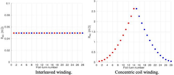
AC resistances of each turn. (N1: red points N2: blue points).
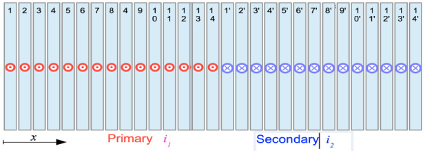
Several applications may require a non-unity transformation ratio. Two transformation ratios are considered as examples: 0.714 and 0.214. The SST input voltage (1500 V) is the same as the rated power; the 14-turn primary is identical. For the first example, (N2 = 10), the SST output voltage is v B ≈ 1000 V; for the second example (N2 = 3), v B ≈ 300 V. The secondary foil-turns are interleaved at the centre of the primary. Figure 9 presents the current density along an x-axis crossing the whole winding. The green rectangle reminds the thicknesses and the locations of the 3-turn secondary example.

Instantaneous value of the current density in the foils at f = 4 kHz and t = 0.
The average current density is +3.12 A/mm2 in the primary and −3.12 A/mm2 in the secondary for both examples. For the second example, the 3 secondary foil-turns are thicker because of the higher current. In these foil-turns, the current density is far from a constant; large eddy current loops flow in the thick secondary foil-turns. The AC resistance referred to the primary is 5.33 mΩ for the second example and 2.07 mΩ for the first one. These values must be compared to the optimum case with a unity transformation ratio (1.38 mΩ). The case N1 = 14, N2 = 3 has winding losses 3.6 times higher than the optimal case.
For designing SSTs with a small transformation ratio, a good solution should be to design the secondary with N2 in the same order as N1 and to split it into several equal parts. The current in each secondary part must be close to the primary one for keeping the same field map for the whole winding. Each secondary part should be connected to its own IGBT bridge with a parallel connection on the DC sides of the bridges. The secondary IGBT bridges’ fine tuning can be used to keep the secondary currents equal. For instance, for the same 14-turn primary, a 12-turn secondary can be split into 4 parts of 3 turns with 4 secondary IGBT bridges.
In the SST presented in Fig. 1, the two IGBT bridges impose the instantaneous voltages: v1 can only take two values ±v A and v2, ±v B . With a single command angle 𝜑 that defines the transferred power, the DC voltages of the two smart grids must be linked by the transformer ratio: v A = (N1∕N2)v b .

Equivalent circuit of the whole SST (left). Voltage imposed to the RL circuit (blue line) and primary current (red line).
In these conditions, the SST equivalent circuit of the left part of Fig. 10 can be used for determining the primary current instantaneous value when the magnetizing current is neglected. The voltage imposed by the two IGBT bridges to the equivalent RL circuit can only take 3 values 0, +2v A , and −2v A . The non-zero values exist during the time lag 𝜑∕𝜔; they impose the current slope for reaching −I R to +I R and conversely. The current remains nearly constant (±500 A) when the imposed voltage is 0 because the resistive voltage drop R AC I R is small compared to the applied voltage during current edges (3000 V). For small values of the command angle 𝜑, the primary current is nearly square.
Table 2 summarizes the main results for f = 4 kHz and a primary rated current I R = 500 A. The actual inductance of the SST equivalent circuit must include the connection wires inductance, which can be estimated to L C ≈ 1 μH for 4 short connections.
Command angle and power factor at the rated current
With interleaved windings, the leakage inductances are very low. The power factor P∕S is very close to 1. However, the SST control must be made with a command angle defined with a high resolution between −1° and +1° for tuning the power from −750 kW to +750 kW. This difficulty can now easily be solved with a command based on a 32-bit microcontroller.
The AC resistances of the analytical model are defined for sine waves. The actual current is nearly square (Fig. 10). Therefore, the winding losses must be computed for the main harmonics of the current and the corresponding AC resistance.
Fourier decomposition of the primary current and losses for each harmonic
The core losses can be determined from the experimental curve presented in Fig. 2. For example, when the cooling system yields a core average temperature of 220 °C at the rated operating point, the specific core losses can be estimated to 140 W/kg. The core mass is 25 kg; therefore, the core losses is estimated to 3500 W. The MFT efficiency is estimates in (13). The value is in the same range as for standard technologies used for lower powers.
The paper presents a solution for designing low leakage inductance windings for a high-power MFT operating at 4 kHz inside the heart of a 750 kW SST. The proposed winding solutions are compatible with hot GOES wound cores. It uses a winding made with two interleaved aluminium foils. The transformer core operates at temperatures higher than the winding to reduce the core losses. The transformer’s mechanical structure avoids the contact between the hot core and the winding. Several small fans provide an airflow between the hot core and the winding.
At 4 kHz, the proximity effect is dominant. A reasonable cost solution consists of using a winding made of aluminium foils. The winding must be designed with wide foils to reach high currents with limited foil thicknesses and a reasonable average current density. Therefore, the core window shape must be adapted to this particularity. Designing such windows with wound GOES cores is easy because the material’s high permeability allows long strips to keep a low magnetizing current. The paper shows that a winding made with two interleaved foils is the best solution for getting low leakage inductances and AC resistances. The main drawback of the proposed structure is a limited choice of the transformation ratio: the primary and the secondary must have a similar number of turns. For building SSTs with large voltage ratios, the low-voltage coil must be split into several smaller coils connected to their own IGBT bridges with a parallel connection on the DC side.
With the proposed medium-frequency transformer structure and now current 6.5 kV IGBT legs, it is possible to build high-power SSTs operating on the medium voltage grid with few elementary cells over 10 MW each at reasonable costs.
Current research focuses on a forced airflow model for optimising the shapes that allow a significant temperature difference between the hot core and the winding at a temperature compatible with standard insulation systems.
Footnotes
Acknowledgement
The authors have no acknowledgment.