
Abstract
With the raise of aircraft performance and the increasing electrical applications, the more-electrical or all-electric aircraft will become the main aircraft model in future. The reliability assessment of aircraft electric power system is critical to guarantee the reliable operation of the aircraft. A reliability assessment method for complex power system of large aircraft such as Boeing 787 has been described in this paper. First the aircraft power distribution system is abstracted as a topology diagram based on the graph theory. Then the minimal path sets are searching from the source node to the load nodes by the depth-first search. These path sets can represent the normal power supply path of the electric power system. Finally, using the raw reliability data of components, the reliability function of various important buses is established and the reliability index of large aircraft power distribution system is calculated. This assessment method can be used to analyze and assess the reliability of power supply and distribution system of different models and to provide a reference for the design and analysis of complex electric power system of civil aircraft.
Keywords
Introduction
With the development of more electric aircraft for civil aircraft, aircraft power system network structure increasingly complex and large, safe and reliable operation of aircraft electrical systems for ensuring flight safety is very important. Therefore it is necessary to select the appropriate method to evaluate the reliability of aircraft electric power system. It is important to evaluate whether the aircraft power system reliability achieves the desired design goals and to promote reliability growth.
There are many reliability analysis methods have been used in the aircraft power system. The fault tree analysis method can be used in aircraft reliability analysis [1, 2]. Although this method is universal, and can be used to demonstrate compliance with the corresponding requirements, but for such a complex distribution network such as B787, the grid analysis modelling is overworked.
FMEA is a standard systematic analysis approach that identifies potential fault modes in a system and assesses the criticality of such fault modes to overall system operation [3].
In paper [1, 4], Bayesian Analysis (BA) treats parameters as random variables and defines probability as “degrees of belief” i.e. the probability of an event is the degree to which you believe is true. This element of belief in parameters is instilled in a prior distribution. Combining information of a given data set of said parameter with the prior distribution will formulate a posterior distribution.
Reliability evaluation algorithm is used in analysis of the more electric fighter aircraft electrical system [5]. In this method faults tolerance ability of EPS in MEA is focused in the analysis process, Euclidean distance and entropy are adopted according to the topology of the system. But this method is over workload in analysis of the reliability of the complex network structure.
In the field of communication network system, reference [6] presents a method for finding the connection matrix for the logic diagram of the communication network. This method helps to automatically search various possible paths from a source point to an endpoint through the computer when network nodes are numerous and connected networks are complex. Reference [7] presents a method based on the supply power path set from load point to power point is used to analyze the reliability of traditional aircaft distribution network.
In this paper, the method of minimal path set is used in topology analysis of the B787 power distribution structure. The method is simple to calculate and is used in many domains [8, 9, 10]. According to the different condition of aircraft power system, system reliability is evaluated by using the depth of the search method. The reliability data of aircraft components can be used to calculate the entire aircraft power system reliability. And this method can provide reference for aircraft reliability management and discover weak points of aircraft power supply system. The following text will describes the method used in reliability analysis of complex aircraft power system such as B787.
The distribution principle of Boeing 787 power system
The configuration of B787 power distribution system
A major feature of the Boeing 787 distribution system is the circular electric grid connected with the bus bars. Four major bus bars in the system are interconnected, at the same time power output terminals of Aircraft Start generator (ASG) are connected to this loop. The advantage of this approach is to avoid loss power supply in the generator failure. This is a good solution to the problem that conventional aircraft generator failure will lead to the corresponding electrical load failure. Because of this approach, when a generator failure the corresponding independent bus bar can obtain power from other electric power supply. However, other power source supply power to the failure bus bar is a matter of priority.
The Boeing 787 aircraft power distribution system is divided into Primary Power Distribution System (PPDS), Secondary Power Distribution System (SPDS) and Remote Power Distribution System (RPDS). PPDS is similar to the traditional distribution system. Usually the main bus bar and the bus bar of different voltage levels converted from the PPDS are classified as PPDS. High power load can directly obtained power from PPDS through Electrical Load Control Contactor (ELCC), this also belongs to PPDS. Reliability analysis method selected can make good application effect in using it in B787 power distribution system. In order to prove this idea, this paper only analysis some main bus bars reliability of PPDS in B787. The above distribution diagram of B787 can be simplified as below in Fig. 1 [7] and the acronym in the Fig. 1 are shown in Table 1.
The description of the acronyms
The description of the acronyms
The simplified diagram of B787 power distribution [11].
B787 power distribution network topology schematic diagram.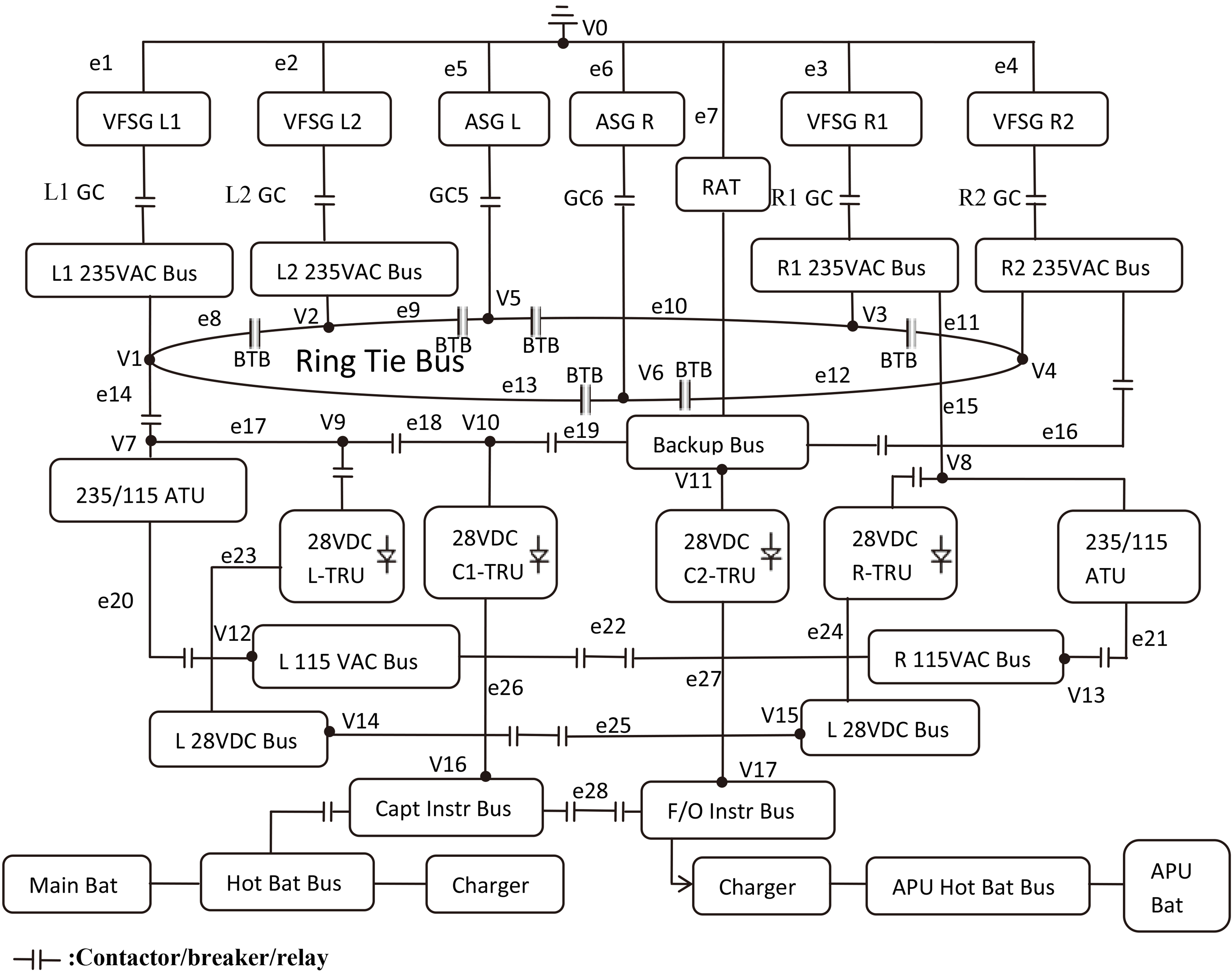
In the Figs 1 and 2 priority path is determined on the number of Bus Tie Breakers (BTBs) in power supply circuit. If the number of BTBs in clockwise direction along the electric power loop is less than the number of BTBs in counter-clockwise direction, the clockwise direction is the first priority and the counter-clockwise direction is the second priority. Conversely, the counter-clockwise direction will be the first priority. If the two numbers are same, then the clockwise direction is the first priority.
Taking L1 235VAC Bus as an example, in normal operation L1 GC is closed, L1 235VAC Bus is powered by the VFSG L1. When VFSG L1 failure, power is supplied from the ASG R which power path is in priority. When ASG R doesn’t work, L1 235VAC Bus is powered by VFSG L2. The VFSG R2 is fourth priority, L ASG is fifth priority [11]. VFSG R1 is the lowest priority to L1 235VAC Bus. Eventually, the load can be powered by other standby power supply paths when the normal power supply path is not working properly. The feature of the B787 source priority is different from other traditional aircraft.
The power supply priority of 235VAC main bus bar in B787:
L1 235VAC Bus: VFSG L1 L2 235VAC Bus: VFSG L2 R1 235VAC Bus: VFSG R1 R2 235VAC Bus: VFSG R2
The complex system with arbitrary structure can be expressed by topological graph. It is necessary to abstract the aircraft power supply and distribution system into a topology graph to reflect the topological structure and working state of the aircraft power supply and distribution system.
In order to satisfy the above principles, the following concrete methods of abstracting the complex power supply and distribution system of large aircraft into topology diagram are summarized.
The single node elements in the distribution network, such as the VAC buses and VDC buses, are equivalent to the nodes in the topology network. The two-node elements, such as generators, voltage converter, switches, circuits, etc., are abstracted into arcs in the topology network. In the process of generating the graph, a virtual source node is established, which is the same as the source point of the power supply system. Starting from the source node, the electric energy is abstracted into a directed arc by the output power components such as the engine and battery, so as to distribute the electric energy. In the process of generating the graph, some virtual load points are established. Electrical energy is supplied to the corresponding load by a directed arc abstracted from the output load line. In the distribution system, the unidirectional electric energy transfer elements such as voltage converter, inverter, secondary transistor and so on are abstracted as directed arcs in the network, and the others are undirected arcs. When the elements are only connected in series and there are no bifurcation nodes between them, the series elements are abstracted into an arc, which can reduce the number of arcs and nodes in the topology network and improve the operation efficiency.
In accordance with the above requirements, the topological nodes and branches of the B787 aircraft distribution diagram are defined as shown in Fig. 2. The corresponding topology structure diagram of the distribution system is shown in Fig. 3. V0 is set a source node of the virtual network, the VFSG L1 and GC1 are abstracted as a directed arc e1. Then the power flow through e1 to v1 which is abstracted as the node of the L1 235VAC Bus. Similarly, generator VFSG L2 and generator circuit breakers GC2 are abstracted as arc e2. L2 235VAC Bus is abstracted as node v2. The power route of Ring Tie Bus supplied by ASG Land ASG R are abstracted as arc e5 and e6. The power route of the Backup Bus supplied by RAT is abstracted as arc e7. The Backup Bus is abstracted as node v11. Other positions of arcs and nodes can be seen in the Fig. 2.
Distribution network topology of B787.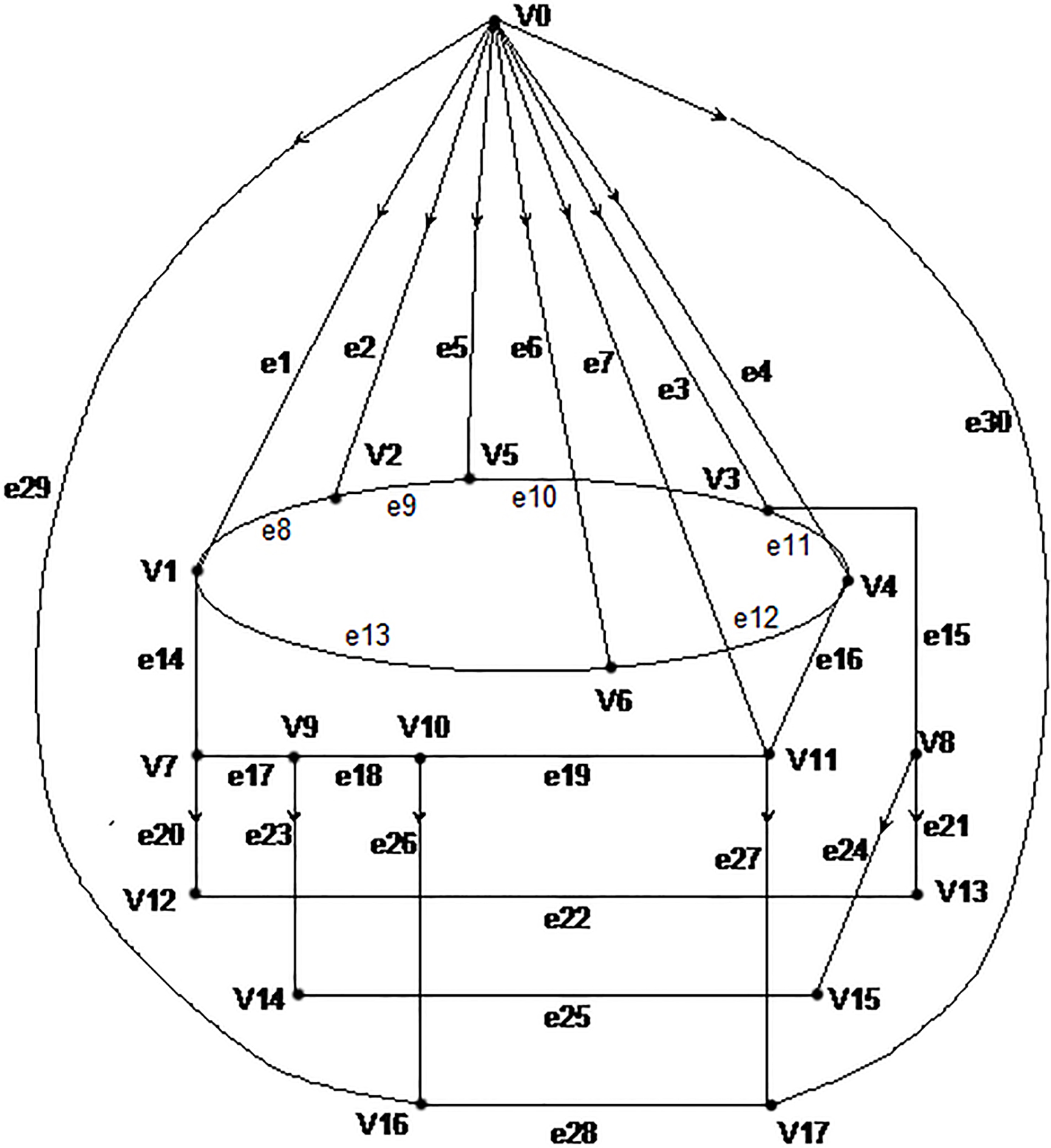
The path with single direction power transmission components like TRU and INV should be abstracted as a directed arc in the topology. The power supply path with only AC BTB or DC BTB should be abstracted as undirected arc.
The establishment of aircraft supply and distribution network topology is based on minimal path method. The basic thought of minimal path is searching the minimal path for each load point, and according to the actual situation of the network, converting the load point reliability affected by failure component in the non-minimum path to the corresponding minimal path node reliability. The corresponding load point reliability indices can be availed by calculating reliability data of the most path elements and nodes [2]. By using this algorithm, the influence of branch line protection and segmented circuit breakers is taken into account, and this method is able to deal with the situation with the standby power or not. Combined with the actual configuration system in this method, the weakest link in the system can be pointed out.
According to the power network topology, the output node is searched using the depth first search method (DFS). The search route is from the input node V0 of the network to the output node which is found. Then repeat this process until all the minimal paths are found.
This paper takes Backup Bus as an example, sets v11 as output node, and considers the priority of AC power supply. By this condition, separately lists the minimal paths of route powered from source node to Backup Bus through L1 235VAC Bus, route powered from source node to Backup Bus through R2 235VAC Bus, route powered from source node to Backup Bus through RAT. And make a summary of all minimal path sets which Backup Bus powered in Table 2. There are 23 kinds of power supply paths from the AC generators to Backup Bus. It is easy to find all of the complete power supply paths and to reflect the supply priorities of the B787 aircraft by this method. What’s more, it can reflect that the annular connecting bar is higher reliability than the traditional distribution network. The minimal path sets of L 28VDC Bus, R 28VDC Bus, L 115 VAC Bus, R 115 VAC Bus, Capt Instr Bus and F/O Instr Bus can be calculated by the same method. Then the reliability data can be calculated and analysed.
Minimal path set of B787 standby power supply bus
Minimal path set of B787 standby power supply bus
Reliability data index of aircraft power system
The reliability data index of aircraft power system and its components can be quantified represented by several index such as reliability
For an arc in topological graph, when the arc is composed of a plurality of series components, then the fault rate of the arc can be converted according to Eq. (2).
In the above equations:
There are many arcs points or away from the node in the topology map. Each arc is equivalent to a branch of distribution system. The node may be influenced by diffusion fault branch and out of operation, what is worse, it will result associated load points loss of power. According to the topology map of distribution power system, the expansion fault rate of the corresponding node can be converted as the fault rate of this node. Then the rate will be used in the reliability evaluation. In the process of converting, only the first-order electrical switch protection tripping fault will be considered. And the first-order tripping fault is that two or more subordinate relationship switch protection appliances will not be fault at the same time.
Set reliability of the distribution system bus bars or terminal nodes as
In the above equation:
When the device lifetime disobeys exponentially distributed, the target load point reliability of different time can be calculated according to the element reliability function. Then supply power reliability of the load point can be calculated on corresponding moment.
The raw reliability data for the Boeing aircraft power distribution system composed elements are shown in Table 3 [8]. Combining power supply minimal path sets of all major bus bars in Table 1, and taking the diffusive fault rate data for each component into the Eqs (2) and (3), then the node fault rate of the corresponding bus bars can be obtained [9, 10, 11]. The results are summarized in Table 4. Figure 4 shows the reliability variation with time obtained according to the Eq. (1).
Original reliability data of Boeing aircraft parts
Original reliability data of Boeing aircraft parts
Fault ratio of Boeing 787 important bus
Reliability curve of Boeing 787 bus.
According to the calculation results of the bus bar reliability, B787 aircraft power supply reliability data of the main load points can be obtained. Firstly, it can be seen from the Fig. 4 and the Table 4 that, in the case of AC power supply, the power supply reliability of the standby bus is higher than other AC bus’s. Because the backup bus is connected to the alternator on both sides and RAT, the power supply path is more. It accords with the design requirements of the flight safety critical AC load distributed in the standby bus.
Secondly, L or R DC bus load is more reliable than corresponding AC bus load. On the one hand, the DC bus is directly connected with the backup AC bus to improve the reliability. On the other hand, the 28 VDC TRUs on the left and right sides can be operated directly in parallel when they work normally. So there are more supply paths for the DC bus.
Of course, in the aircraft design or management, if the aircraft power system needs to add battery for reliability analysis, the corresponding nodes and branches can be added to the minimum path cut set analysis.
Through the power supply reliability analysis of B787, the power supply minimal path set is more shown in the Table 2 and power supply reliability is higher than the traditional aircraft’s. The main reason is that B787 have more power sources. Each engine drives two generators. In the traditional aircraft each engine drives only one generator [7]. The power supply system of traditional aircraft is the radiation power network structure. The supply path is interrupted when a power supply fails. The power supply system of B787 is the annular power network structure. Each power source is connected to the common annular bus. When a power supply fails, the power supply path can be switched to other power source through GCs and BTBs on the annular bus. The number and length of distribution wires can be reduced. The electric power system of B787 operates more flexible and reliable.
This paper analyses the configuration of the B787 ring power supply network systems in detail and searches for supply power path of the B787 aircraft emergency power bus bars under various working conditions by the minimal path set. The conversion and calculation of the topology reliability data are achieved according to the minimum path. The method can realize the analysis of power supply reliability data for all aspects or components of the aircraft power system. The reliability and fault rate calculation results of the B787 power system can provide theoretical basis for the power reliability management of complex power distribution grid of aircraft power system. It also can provide some reference and help for the design and optimization of aircraft power supply and distribution system, as well as the operation decision.
Footnotes
Acknowledgments
The authors acknowledge the National Natural Science Foundation of China (51377161, U1533126, 51407185).