
Abstract
Instability problem of a hydrodynamic plain journal bearing at higher speeds is conventionally resolved by using the non-circular bearings. High speed precision rotating shafts demands accurate positioning of the journal centres. A multi-pad adjustable bearing is a non-circular bearing, provides a fine-tuning option of the journal centre by continuously changing the bearing profile. In the present study, the bearing has a configuration of four bearing pads that are adjustable both in the radial and tilt directions. The fluid film thickness profile is conventionally obtained using the trigonometric relations, which has computational limitations, especially in multi-pad adjustable bearings. In this investigation, the film thickness profile of a multi-pad adjustable bearing is mathematically formulated using the transformation technique. The results obtained are compared with those available in the literature for a similar bearing. The observation shows that transformation technique eliminates the projection approximation error present in the conventional technique.
Keywords
Introduction
NON-CIRCULAR bearings are used to counter the instability problems occurring in conventional full journal bearings at high speed and loads. Currently, there is a wide range of bearing designs which are available with fixed bearing profile and tilting pad configuration. In these bearings, the bearing profile is a dependent function of operating conditions; also the bearing profile cannot be adjusted during the time of operation. This opportunity triggered the invention of bearings with adjustable configuration. An externally adjustable fluid film bearing contains two interchangeable spacers for radial and circumferential adjustments. These adjustments help in real-time fine-tuning of the film thickness to maintain the accurate positioning of the rotating shafts.
The first adjustable bearing was designed by Martin and Parkins (U.S. Patent No. 5,772,334, 1998). The static performance characteristics of an externally adjustable bearing containing four adjustable bearing element were explained by Pai and Parkins [1]. It was observed that an externally adjustable bearing could support a load at zero eccentricity. Also, the power absorbed by this bearing design is less than available non-circular bearings without affecting performance. A mathematical model of externally adjustable bearing was developed by Martin [2]in 1999 considering the inverse arrangement, where a stationary journal supported the rotor. In this work, a generalized equation was proposed to determine the film thickness variation. In addition, temperature and viscosity model was also developed. Hariharan and Pai [3] explained the mathematical formulation of the film thickness of an externally adjustable bearing considering the same adjustment criteria for bearing elements, focusing on trigonometric relations to express the film thickness variations. A tilt and radial adjustment superimposing technique to calculate the film thickness variation of a single pad adjustable bearing was further described by Shenoy and Pai [4, 5]. It was also observed that misalignment in the bearing will significantly influence the fluid film thickness. These changes can occur either in any of three planes or in combinations of planes. Turbulence effects, effected the static performance of a single pad externally adjustable as reported in Shenoy and Pai [6] which explained the film thickness evaluation method considering single plane mis-alignment.
The available experimentation results proved that in large adjustable bearings a good control over the journal centre can be achieved by reducing the journal orbit Martin and Parkins [7, 8]. Variable geometry bearing is another group of non-circular bearing, used in the vibration quenching technique. Chasalevris and Dohnal [9, 10, 11] proposed a technique to derive the film thickness in the variable geometry bearing by using two separate functions of a coordinate angle. The active adjustments of the radial gap of a gas foiled bearing were explained by Polyakov et al. [12]. In this technique, the authors used electromagnetic forces to get the controlled deformation of the foil, and the film thickness was calculated as a function of the number of elements present in the radial clearance. The film thickness in the foil bearings can also be expressed as the mean foil height and the locality-based foil variation function Guenat and Schiffmann [13] and Samanta and Khonsari [14].
Partial arc bearing with radial adjustments improves the stability of the industrial turbines. In this type of bearings, the fluid film thickness variation is generally expressed as the function of circumferential coordinates Chasalevris and Dohnal [15, 16].
A projection technique of journal axis is used by Manser et al. [17] to project the journal axis to consider the misalignment in the axial and circumferential direction of a textured journal bearing. In an investigation of misalignment on a tilting pad bearing, such and choi [18] explained a technique to calculate the film thickness by using pitch and yaw motion of tilting pad bearing. A film thickness equation for a tilting pad bearing containing the textured surface was derived by Gropper et al. [19], considering the relation of locations of pivot and pitch angle. The surface texture depth was incorporated in the equation by adding the texture depth in the locations where textures are located. The film thickness of the tilting pad bearing can be expressed as the sum of steady oil film thickness and increment in the oil film thickness [20]. The increment in the oil film includes the film thickness at the pivot and the effect of radial tilting angle.
Several previous studies proposed many techniques to estimate the film thickness of model specific non-circular fluid film bearings. It was observed that in multi-pad externally adjustable bearings, the film thickness is a dependent function of both tilt and radial adjustments. Hence there is a need to develop a technique to determine the general film thickness which is capable of handling the flexibility of taking symmetric, asymmetric and random adjustments. The present study proposes a fundamental approach to develop transformation techniques to evaluate the film thickness equation.
Configuration of multi-pad adjustable bearing
A schematic representation of multi-pad adjustable bearing is shown in Fig. 1. A bearing element can have three radial adjustments, and in a given position each element of the bearing can have three tilt adjustments. The tilt and radial adjustments will change the bearing centre from the global coordinate origin. The
Basic transformation operations [21]
Basic transformation operations [21]
Multi-pad adjustable bearing basic configuration.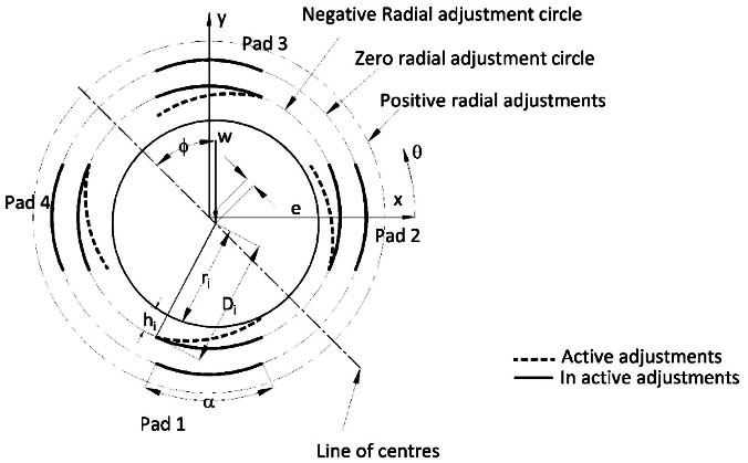
Geometric transformations are widely used in computer graphics. The transformation operations convert the geometry from one coordinate system to another coordinate system. A rigid body transformation can be achieved by using translation, rotation, scaling and reflection individually or in combinations. In rigid body translation, every point on the body moves an equal distance in a specified direction. The magnitude of translation can vary from one direction to another. A rigid body can be rotated with respect to any other point within the body or outside the body. The reference point of rotation and the direction of rotation decides the final configuration of the body. Scaling operation is used to change the size of the object with respect to any reference point. The scale factor used in this operation can have different values in different directions. Refection operation is useful in modelling symmetric objects. Transformation matrices in two dimensions are shown in Table 1.
An adjustable bearing element has radial and tilt adjustment. The adjusted positions of all the points on the surface of the bearing element can be evaluated by using translation and rotation operation. The translation operation captures the effect of radial adjustments; rotation operation captures the effect of tilt adjustments. The sequence of applying the transformation matrix has a significant role in the final coordinate of the points. To concatenate the transformations Homogeneous representation method is adopted.
A global coordinate system was defined at the centre of the bearing when all the bearing elements have zero adjustments. All adjustments are given with respect to the global coordinate system, and the centre of the bearing for the adjusted position was located by using a flexible polygon, which is formed by joining the centres of four pads. The straight line distance between any point on the bearing profile and the journal centre can be calculated by using the distance formula as given in Eq. (1).
where,
where,
The tilt adjustment given to the pad is with respect to the pivot point. The negative tilt for all the nodes is given by applying the anti-clockwise rotation matrix, whereas a positive tilt effect is imparted by applying the clockwise-rotation matrix. Individual pads will have individual pivot points. A general expression for the transformed coordinate is obtained by translating all the pivot points to the global origin. After performing the rotation operation, the coordinates are reverse translated by the same distance. The translation distance depends on the position of the pivot point. The bearing centre is defined by the arithmetic mean of transformed coordinates as given Eqs (3a) and (3b)
where,
The difference between calculated distance and the radius of the journal at any location on the bearing element surface will result in the film thickness corresponding to that location. Mathematically the film thickness equation in the matrix form can be expressed as shown in Eq. (4)
where,
The physics of any complex lubrication problem can be mathematically formulated by using the Reynolds equation with suitable assumptions [22].
For steady state condition, the squeeze term in the Reynolds equation is neglected.
The solution of the Reynolds equation includes integration constant. The flowing pressure boundary conditions are used to evaluate the integration constants
This boundary condition leads to the negative pressure generation in the fluid film which is impractical. Hence, this problem can be solved by equating the generated negative pressure to zero in each iteration thus satisfying the actual condition [23].
Multi-pad adjustable bearing (a) one asymmetric pair adjustments (b) flexible polygon to evaluate the bearing centre.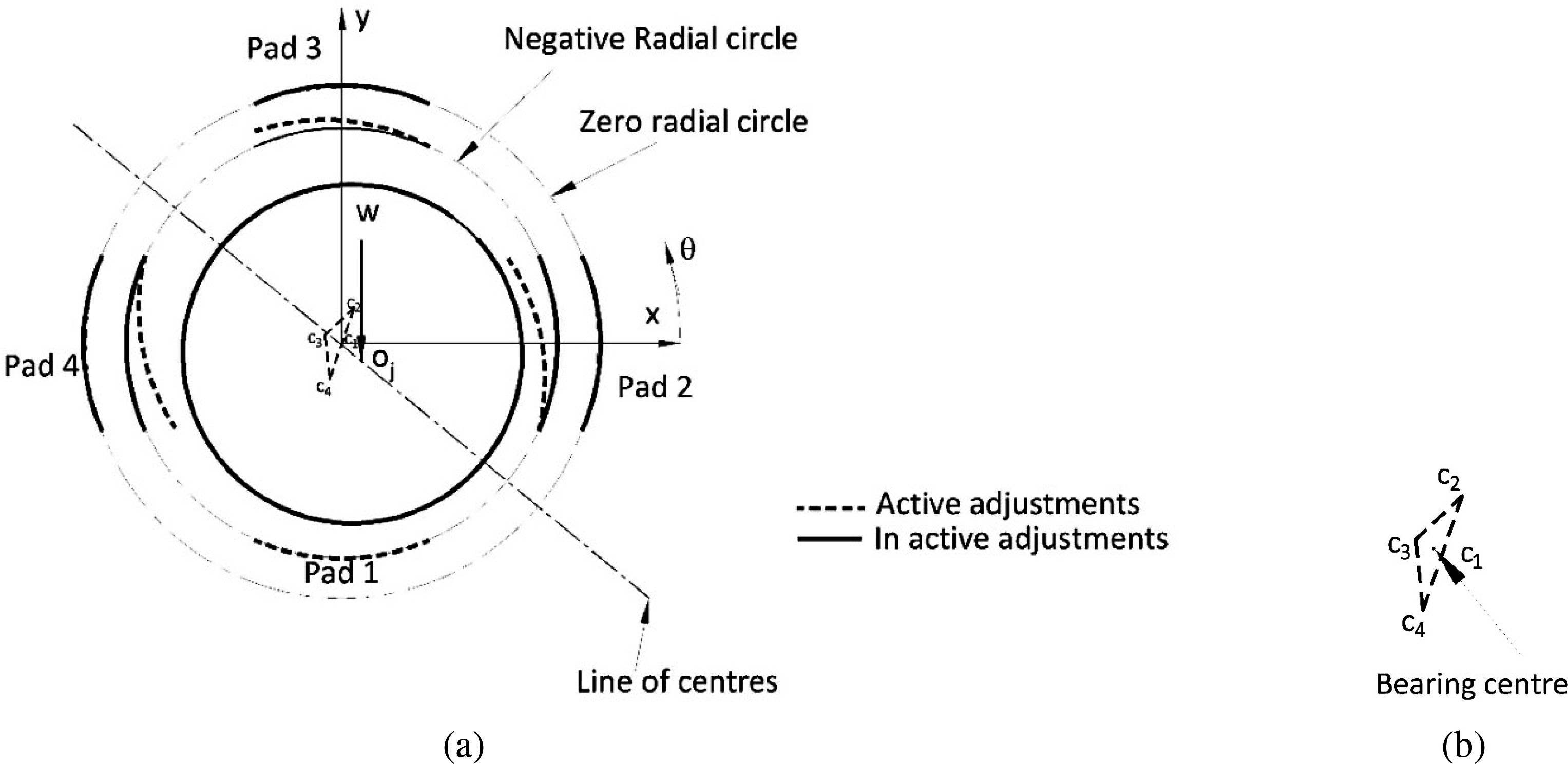
Solution Scheme for multi-pad adjustable bearings.
Comparison of film thickness variation obtained from the present method with Hariharan [3]. (a) Pad 1 (b) Pad 2 (c) Pad 3 (d) Pad 4.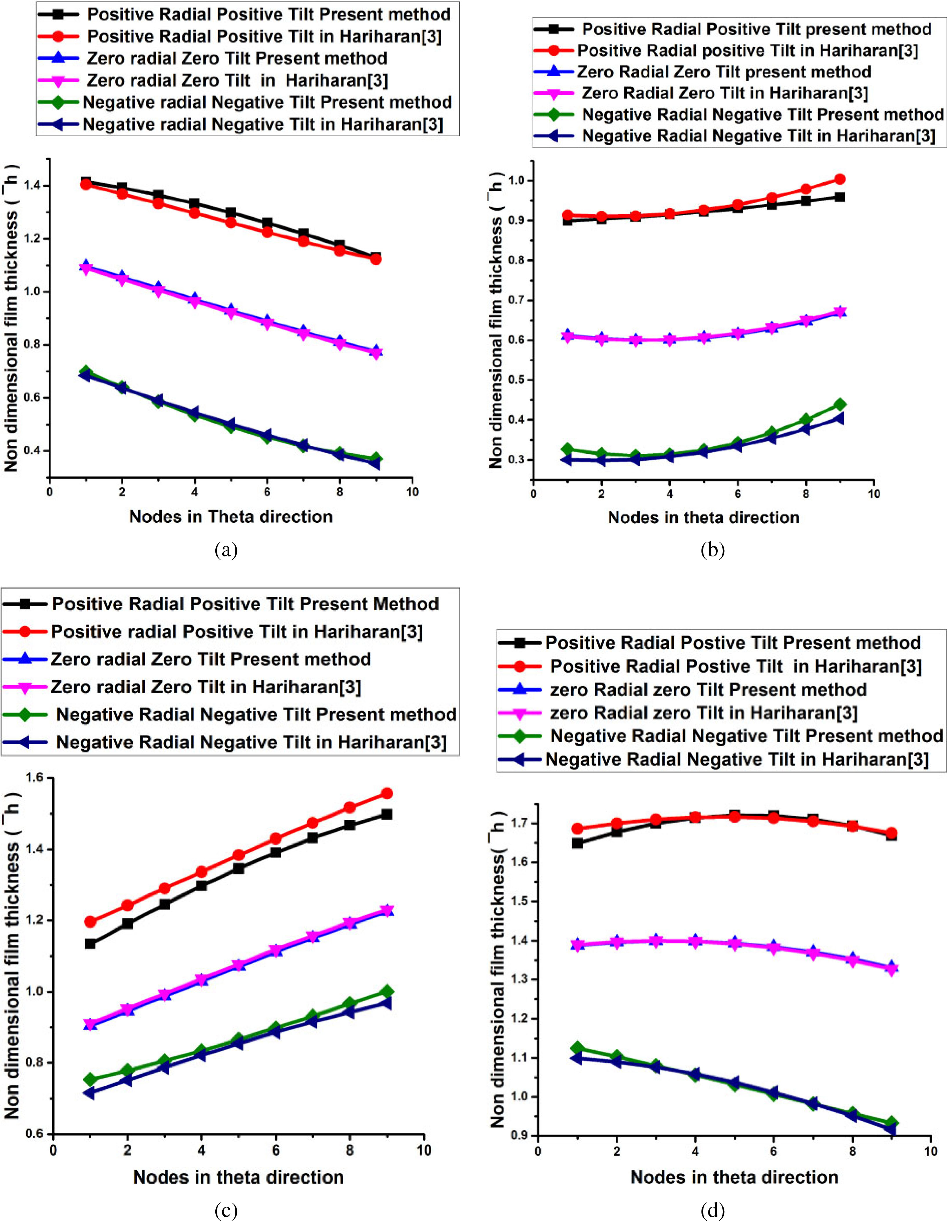
The solution scheme starts with the assumption of the initial value for the attitude angle. Corresponding to the assumed attitude angle the film thickness variation in different pads is calculated. Figure 2 shows the solution scheme for the multi-pad adjustable bearing. The pressure distribution in the fluid film is obtained by solving the Reynolds equation in the computational domain. The generality of the solution can be extended by non-dimensionalizing the Reynolds equation. A non-dimensional form of the Reynolds equation [24] is given in Eq. (8)
where,
The pressure calculation is an iterative procedure; a numerical code is developed using MATLAB R2016b to evaluate the pressure distribution in the fluid film with convergence criteria of 10
The attitude angle calculated in the equation is compared with the assumed value
The nonlinear variation of fluid film thickness in multi-pad adjustable bearing having symmetric adjustments is calculated by Hariharan [3]. The result obtained from the present method is compared with Hariharan [3] for symmetric adjustments of the bearing elements and eccentricity ratio 0.4. The maximum radial displacement given to the pad is
Results and discussion
The film thickens obtained in the present method is showing a good match with Hariharan [3] for (a) zero radial and zero tilt (b) negative radial and negative tilt. For positive radial and positive tilt adjustments, the present method estimates lower film thickness value than Hariharan [3] in pad 1 and pad 2. But, in Pad 3 and Pad 4 the higher value is predicated only near the leading and trailing edge of the pads. This deviation is because of the projection approximations considered in trigonometric methods during the calculation of film thickness value by Hariharan [3]. The present method calculates the film thickness using straight line distance; the projection error has been eliminated.
Multi-pad adjustable bearing with two pair symmetric adjustments (a) Case 1 (b) Case 3.
Bearing centre location for different tilt and radial adjustments.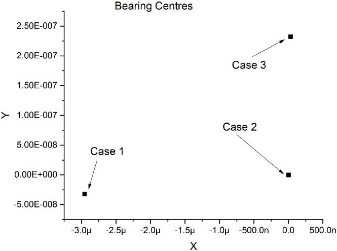
Film thickness variation in different Pads for the three cases of tilt and radial adjustments.
The present method is extended to a multi-pad adjustable bearing having asymmetric adjustments for three different cases. In case 1, a negative radial and negative tilt were given to Pad 1 and Pad 3, a negative radial and zero tilt were given to Pad 2 and Pad 4. In case 2 negative radial and zero tilt were given to all the pads, this is similar to four pad bearing. In case 3, Negative radial and negative tilt were given to Pad 2 and Pad 4, negative radial and zero tilt were given to Pad 1 and Pad 3. The schematic representation of three cases of adjustments is shown in Figs 2 and 5. These combinations shift the bearing centre location to III quadrants, IV quadrant, I quadrant respectively as shown in Fig. 6. The Fig. 7 shows the film thickness variation in four Pads for three different cases of asymmetric adjustments. Minimum film thickness is observed in Pad 2 and the maximum film thickness is observed in Pad 4 for all the three cases. But, the location of the minimum and maximum film thickness is case-specific.
The conventional method of estimation of nonlinear variation of the film thickness of a multi-pad adjustable bearing for asymmetric adjustments has computational limitations. In the present work, a novel method has been proposed to evaluate the film thickness value of a multi-pad adjustable bearing using transformation technique. This method gives the flexibility of giving any adjustments to any of the bearing elements. Further, this method will eliminate the projection error occurring in the trigonometric method of calculating the film thickness; hence it is more accurate compared with the conventional method.