
Abstract
Traditional vision measurement algorithms have many shortcomings, such as complex process, multi-parameter adjustment and the integer pixel accuracy. To solve these problems, a sub-pixel displacement measurement algorithm based on Taylor expansion is proposed. The displacement vector between adjacent frames is modeled in the first step, and then shift equation of the template image is constructed based on assumptions of constant brightness and spatial consistency. After performing a first-order Taylor series approximation, the displacement vector is obtained by least squares estimation. Finally, through iteratively updating the position of template image, displacement is rapidly extracted. In order to verify the accuracy and effectiveness of the Taylor expansion algorithm, the accuracy test of the grating ruler platform in the presence of the target and the vibration measurement experiment on vibration motor in the absence of the target are designed. Experimental results show that, compared with template matching algorithm based on normalized cross correlation, for the experiments mentioned in this paper, the proposed algorithm can control the calculation time for one frame in less than 1 ms, and achieve higher sub-pixel computation accuracy. Compared with the actual set frequency of 10.78 Hz, the measured frequency of the motor is very consistent with a relative error of 1.1%. It also verifies that the Taylor expansion algorithm proposed in this paper is a reliable and effective non-contact measurement method with important practical application value for vibration measurement.
Introduction
With the development of image processing technology, vibration measurement based on vision has attracted people’s attention. It analyzes motion sequences by using image processing technology to complete the recognition and tracking of moving targets and the computation of displacement and trajectory. Different from traditional contact measurement methods (such as accelerometers, linear displacement meters, etc.), vision measurement technology has the advantages of noncontact, remote measurement and no additional mass and does not affect the dynamic characteristics of the detected object [1, 2, 3]. At present, vision measurement has been widely used in many fields, such as displacement monitoring of large bridge structures [4, 5, 6, 7, 8, 9], cable vibration measurement [10, 11], experimental solid mechanics [12], aerospace industry [13], and underwater environment measurement [14].
The essence of vision displacement measurement technology is to complete the displacement measurement of target object by analyzing the video sequences. At present, there are many algorithms for vision measurement [6, 7, 8], which can be classified into the following two categories: 1) based on traditional vision analysis methods; 2) based on template matching algorithms. Lee et al obtained the vibration video of the bridge by using a digital camera [6, 7]. The measurement point was marked with a black and white target. The target recognition and tracking and the vibration displacement computation were realized based on traditional visual image analysis. Kim [8] completed the template matching by calculating the correlation matrix between the template and the video image, and obtained the cable displacement response curve. The main frequency and damping ratio of the cable vibration are obtained through modal identification. However, there are many shortcomings in the implementation of the above vision algorithms. For example, traditional vision analysis requires a combination of image enhancement, edge extraction, texture detection and other processing methods to complete target recognition and tracking. Multiple threshold parameters need to be set during the operation process. These lead to a complex algorithm flow and poor universality for many traditional vision analysis methods. For many template matching algorithms, the formula is complicated, the calculation amount is large, the efficiency is low, and only the measurement accuracy of the integer pixel can be obtained without introducing modifications.
Aiming at the problems existing in vision methods, this paper takes a different approach to model and analyze the motion displacement between adjacent frames from the perspective of Taylor series expansion. Based on the assumption of rigid motion, transform displacement computation problem into image alignment problem. A first-order Taylor series expansion is performed on the matched image. And then the displacement vector is estimated using the principle of generalized least squares. For large displacements, a displacement iterative computation algorithm is further used. In Section 3, the effectiveness of the proposed Taylor expansion algorithm is verified through experiments.
Methods
Vision measurement system
The used vision measurement system in this study is a standard framework for digital image acquisition, which consists of light source, image acquisition device, computer, and image processing software. The image acquisition device is the basis of vision measurement, and the vision analysis algorithm is the core of vision measurement. The goal of the vision analysis algorithm is to calculate the relative displacement between adjacent frames, and then accumulate to obtain the displacement response curve of the entire process. Under normal shooting conditions, the shooting duration is not long, and the deformation of the target object may not be considered. That is, the target object is considered to have only rigid movement, which is represented in the image as the overall displacement of the moving target in the plane. In this study, vision measurement is conducted based on in-plane rigid motion assumption. The following assumptions can be made for in-plane rigid motion:
Constant brightness. Image acquisition is usually performed under constant light conditions and the shooting time is not long, so it can be considered that the image brightness remains constant during shooting; Spatial consistency. When the moving object does rigid movement, it is considered that no deformation occurs or the deformation can be ignored. Under this assumption, the target image maintains spatial consistency and adjacent pixels maintain similar motion.
Based on the above assumptions, the displacement computation problem can be modeled and analyzed as follows. In the first frame, a region on the moving object is selected as the tracking template
Illustration of the process of displacement computation.
According to the assumption of spatial consistency, all pixels of the template
In the (
Since the displacement vector
and transformed as
Where
Since all pixels of the sub-image
Denote
Where
Then according to the generalized least squares, when
According to the above equations, displacement vector can then be estimated.
When the displacement between adjacent frames is small, the accurate displacement vector between adjacent frames can be directly obtain according to Eq. (6). However, in practical applications, the displacement between adjacent frames may be large. At this time, the displacement estimation is no longer accurate.
In order to accurately obtain the displacement vector
The displacement response curve of rigid vibration can be obtained by applying the above algorithm on the whole video frames. This displacement computation algorithm is a tracking algorithm based on template alignment. Compared with feature-based conventional image processing, this algorithm has the following characteristics: target tracking is implemented by identifying the feature of the template so that there is no need to install special markers on the tracking target; threshold selection is also not needed as there is no need of feature computation operation; this algorithm needs fewer adjustable parameters and is more automated; it has sub-pixel accuracy and no additional precision optimization algorithm is needed.
Flow chart of the Taylor expansion algorithm.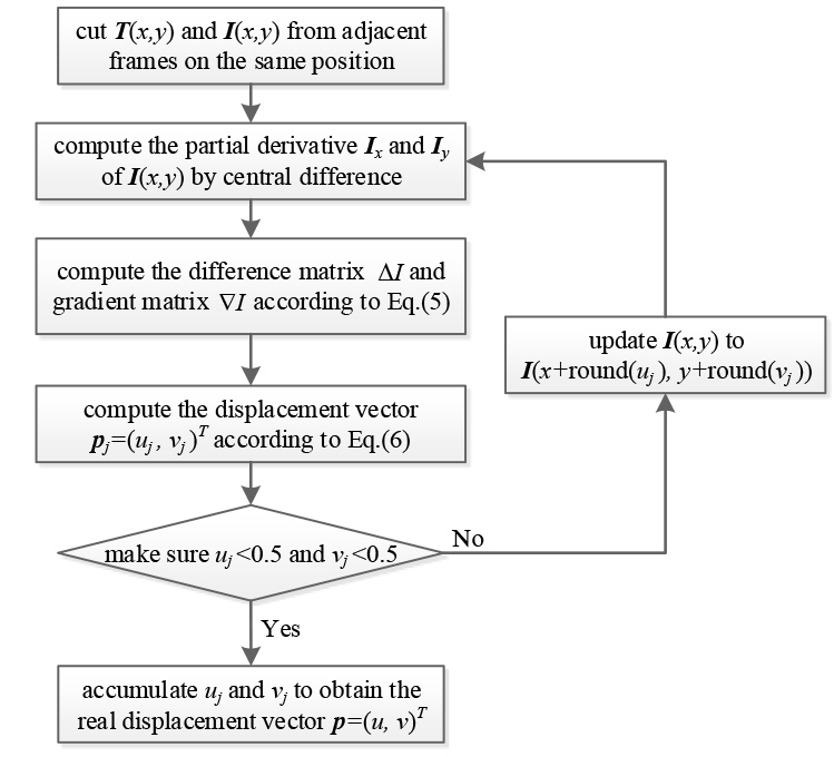
It can be seen from the flow chart of the Taylor expansion algorithm, each algorithm iteration involves an image cutting, an image difference, a collection of image dot-products, a multiplication with the inversion of matrix, and a parameter update. For all the above operations, only a collection of image dot-products is a little more complicated, which is the multiplication of the corresponding positions of the two matrices and then the sum operation. The other steps are very simple numerical and matrix operations. There is no hidden time-consuming interpolation. For a template size of 100
The proposed Taylor expansion algorithm is very similar to the optical flow method, but they are different. In optical flow method [15, 16], the velocities and directions of all pixels i.e. the optical flow field are estimated by using the variation of pixels in image sequences in the time domain and the correlation between adjacent frames to find the correspondence between adjacent frames. The algorithm proposed in this paper is based on the assumption of rigid motion, and the relative displacement between adjacent frames is calculated by numerical iteration. Compared with the optical flow method, the algorithm proposed by us is more convenient for the computation of relative displacement between adjacent frames.
In order to verify the accuracy and effectiveness of the displacement computation algorithm based on Taylor expansion, the accuracy verification experiments of the grating ruler platform in the presence of a target and the motor vibration measurement experiments in the absence of a target are designed.
Accuracy verification experiment of the grating ruler platform
In order to verify the accuracy of the Taylor expansion algorithm, a grating ruler platform experiment as shown in Fig. 3a is established. The grating ruler displacement sensor consists of a grating ruler and a grating reading head. The grating ruler is fixed on the translation stage base, and the grating reading head is connected to the rotating screw through a connection plate. When the screw is rotated manually, the connecting plate and the grating reading head are driven to perform synchronous horizontal movement. The pitch is 0.02 mm, the resolution is 0.001 mm, and the accuracy is
In the experiment, a high-speed camera (Hefei Fuhuang Agile Device Co. Ltd; 2F04-M) is used to shoot the connection board target. The shooting distance is 3 m, the shooting frame rate is 200 fps (duration 10 s), and the resolution is 160 pixel
Effect comparison of Taylor expansion and NCC algorithms
Effect comparison of Taylor expansion and NCC algorithms
Accuracy verification experiment of the grating ruler platform. (a) experiment system; (b) target image.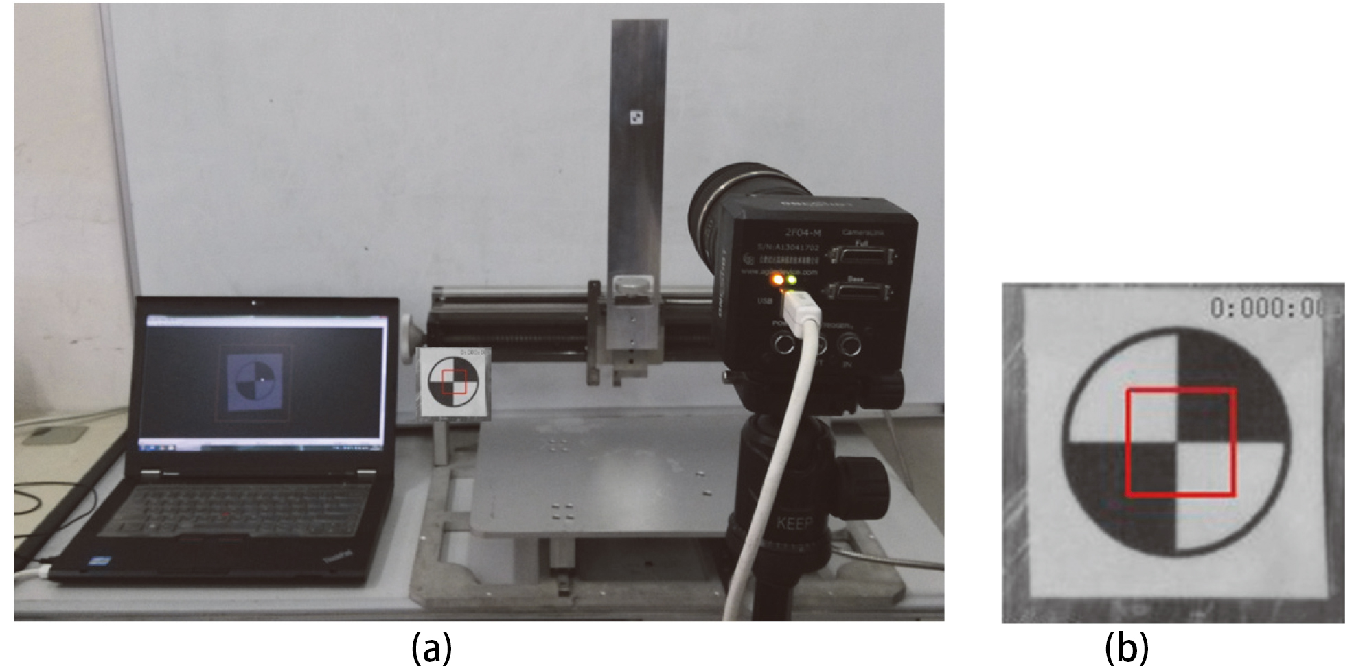
Displacement computation results of the grating ruler platform.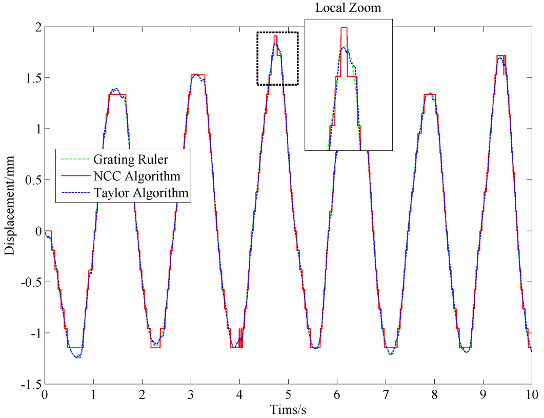
The position of the red frame in the target image is selected as the tracking template. The size of the template is 50 pixel
Figure 5 shows the statistics of the elapsed time of displacement computation for each frame of Taylor expansion algorithm and NCC algorithm. For the Taylor expansion algorithm, the displacement computation converges within 3 iterations. 85% of the displacement computation is completed in 0.2 ms, and the average time is 0.22 ms. For the NCC algorithm, the displacement computation time is more than 5 ms for each frame. The average time is 5.93 ms. Compared with the NCC algorithm, the calculation efficiency of the Taylor expansion algorithm is nearly 27 times higher. The algorithm effect is shown in Table 1. The above results show that the Taylor expansion algorithm proposed in this paper is an efficient and high-precision displacement computation algorithm with reliable practical performance.
Comparison of elapsed time for each frame. (a) Taylor expansion algorithm; (b) NCC algorithm.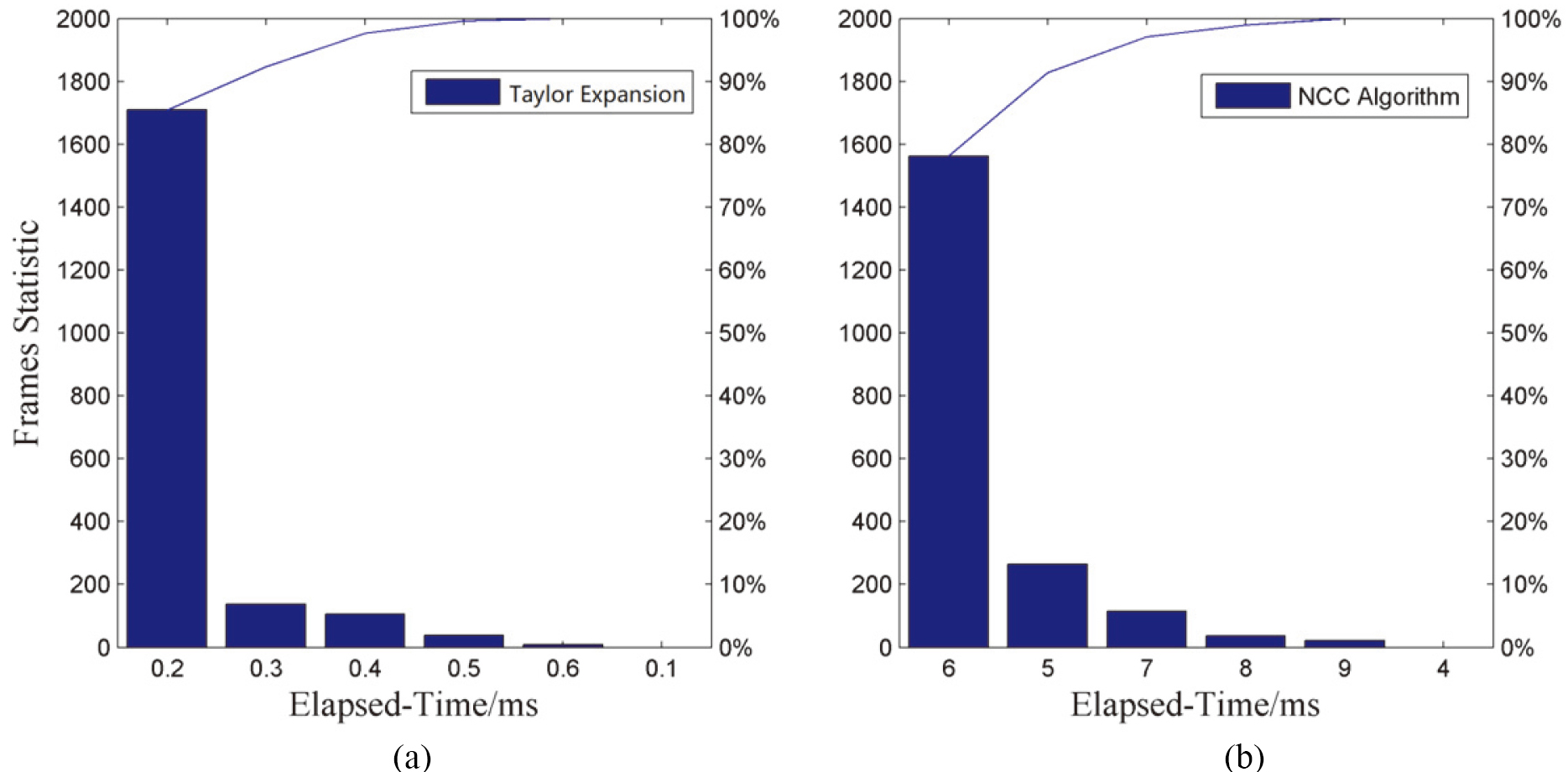
Vibration-measuring experiment of motor. (a) shooting of vibration motor; (b) motor controller; (c) a vibrating image of motor.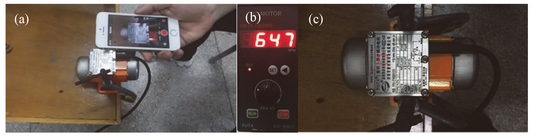
Results of displacement measurement on vibration motor. (a) 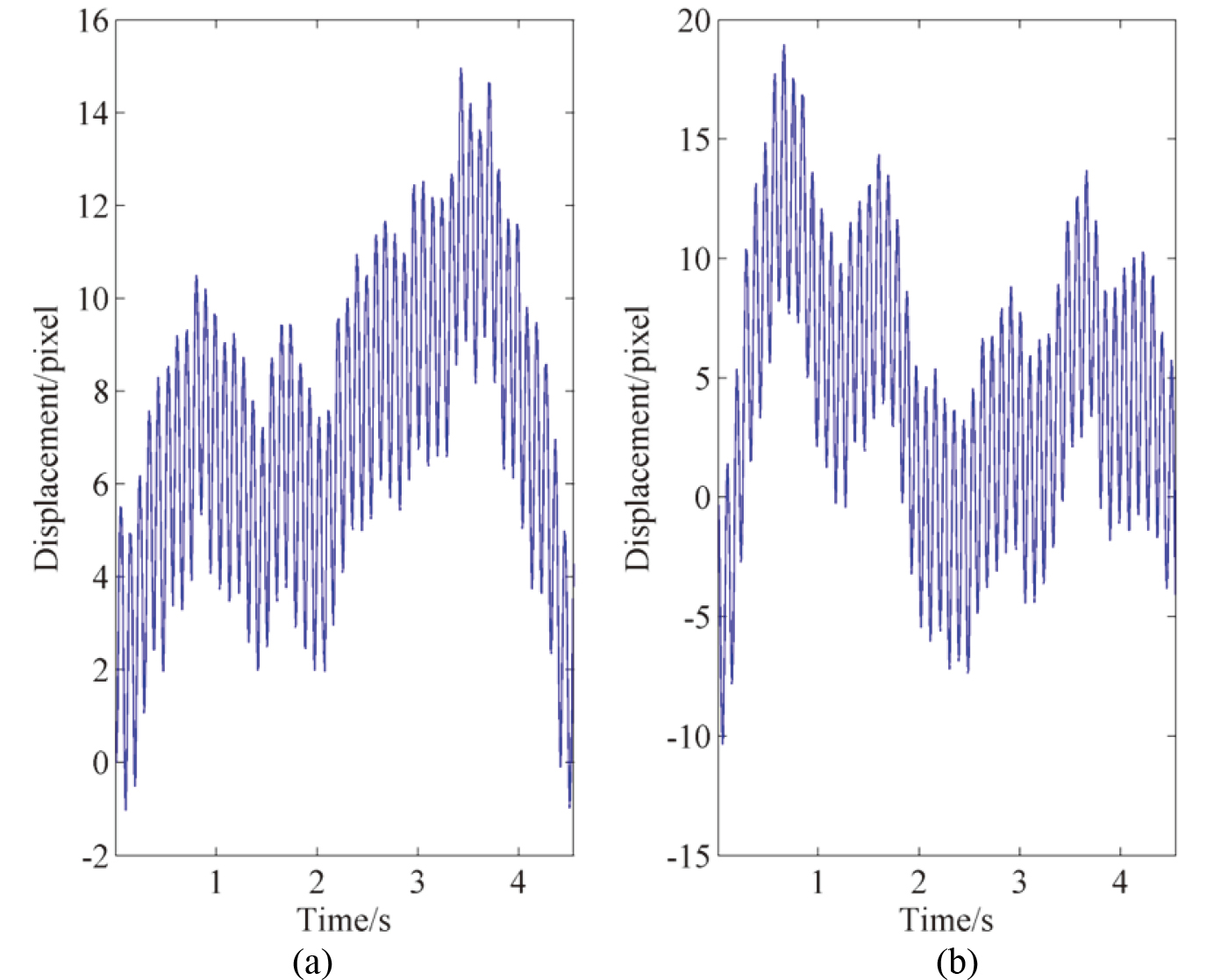
Speed and spectrum of vibration motor. (a), (b) speed on 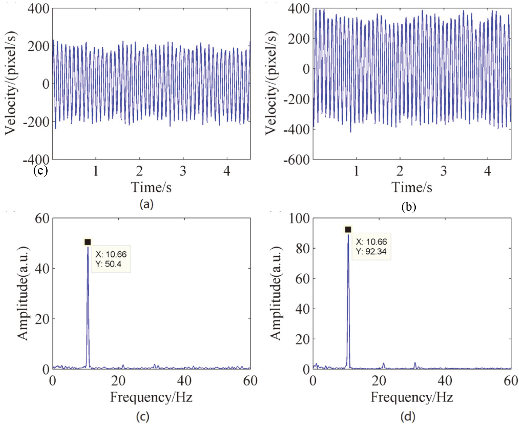
The following uses motor vibration measurement experiments to verify the effectiveness of Taylor expansion algorithm in practical applications, as shown in Fig. 6. Figure 6a is a hand-held shooting of an asynchronous motor in vibration using the iPhone 5s’s slow-motion camera function. The shooting rate is 120 fps. Figure 6b is a vibration motor controller, which shows that the motor speed is 647 rpm (the corresponding frequency is 10.78 Hz). Figure 6c is a frame in the obtained video. The motor nameplate marked with a red frame is used as a tracking template to complete the displacement computation based on Taylor expansion.
The displacement computation results obtained are shown in Fig. 7. It can be seen from the extracted vibration curve that due to the jitter of the arm during shooting, the extracted displacement curve shows the phenomenon of high frequency riding waves superimposed on the low frequency trend. The low frequency trend reflects the jitter of the arm, and the high frequency riding wave is actual motor vibration. In order to eliminate the influence of low frequency components in the spectrum analysis, the vibration spectrum information can be obtained by differentially calculating the speed. Figure 8 shows the velocity curve and its frequency spectrum obtained from the displacement calculation. As can be seen from Fig. 8, there are obvious spectral peaks in both the
In summary, the Taylor expansion algorithm proposed in this paper can effectively complete vision-based displacement and vibration measurement. It has good measurement accuracy and efficiency, and also verifies that vision measurement is a reliable and effective non-contact measurement method.
Conclusion
In this paper, a displacement computation algorithm based on Taylor expansion is proposed. Based on the assumption of rigid motion, the algorithm uses the least squares principle to obtain a matrix estimate of the displacement vector between adjacent frames. After performing a first-order Taylor series approximation, the displacement vector is obtained through the template position update and iteration. The accuracy verification experiments of the grating ruler platform in the presence of the target and the field vibration measurement experiments of the motor in the absence of the target proved the efficiency of the algorithm. Compared with the template matching algorithm, the execution speed of the Taylor expansion algorithm is 27 times faster and can achieve higher sub-pixel computation accuracy. The measured frequency of the motor is very close to the set frequency with a relative error of 1.1%. For the proposed algorithm, target tracking is implemented by identify the boundary or veins of the template so that there is no need to install special markers on the tracking target; threshold selection is also not needed as there is no need of feature computation operation; this algorithm needs fewer adjustable parameters and is more automated; it has sub-pixel accuracy and no additional precision optimization algorithm is needed. It is a reliable and effective vision measurement method with important practical application value. However, the algorithm proposed in this paper is based on the assumption of rigid motion. For more complex motions or non-rigid motions, further improvements or more suitable algorithms need to be studied.
Footnotes
Acknowledgments
The authors acknowledge the Key Project of University Natural Science Foundation of Anhui Province (Grant No. KJ2017A925); Major Science and Technology Projects of Anhui Province (Grant No. 18030901033); Natural Science Foundation of Anhui Province (Grant No. 1908085ME135).