
Abstract
Targeting at the axial magnetic bearing, a structure of laminated six-ring redundant axial magnetic bearing, which is featured in both high redundancy and low heat, was designed in this paper. Meanwhile, the design criteria of the laminated redundant axial magnetic bearing was proposed, and the theoretical research, numerical simulation and empirical research on the redundancy and electromagnetic force of the laminated redundant axial magnetic bearing were conducted as well in this study.
Introduction
Magnetic bearing is a new type of bearing that makes the rotor suspend without contact by the controllable electromagnetic force produced by electromagnet. Compared with traditional bearings, it is featured in multiple advantages like no abrasion, no pollution, no need of lubrication, and adjustable stiffness and damping [1, 2, 3, 4]. The electromagnetic suspension technology has been widely applied in more and more high-tech fields, such as ultra-high-speed and ultra-precision machining, aerospace, etc. [5, 6, 7, 8]. During this process, how to improve the reliability of this equipment has become a key factor for its continuous development and research. And accordingly, how to further improve the reliability of the active magnetic bearing has also become the hotspot research point for both home and abroad. In order to make the electromagnetic suspension system more reliable, redundant reconfiguration is one of the most common methods used by domestic and foreign experts [9, 10, 11].
Up to now, researches of both home and abroad on the magnetic bearing redundancy are as follows: Chen proposed a design scheme for redundant radial magnetic bearings, obtained the conclusion that it’s a weakly coupled structure through simulation analysis, defined various failure modes according to the characteristics of this structure, and put forward a failure compensation strategy based on the thoughts of force balance compensation [12]. Maslen and Meeker took the bias current linearization theory as the basis to compensate the electromagnetic forces by method of re-allocating the current passing through unfailed coils, and further studied the relationship between the compensation current and the electromagnetic force after experiencing redundant reconfiguration, which provided theoretical basis for the fault-tolerant control of the magnetic system actuator [13]. Na and Palazzolo conducted a theoretical study on the fault-tolerant performance of the radial magnetic bearing which has eight-pole heteropolar arrangement by the current distribution matrix, showing that, as for the radial magnetic bearing with eight-pole heteropolar arrangement, its rotor would achieve stable suspension as long as having no failure of 5 poles or above [14]. Wang et al. proposed a new redundant structure, which was proved to have weak coupling effects, and is better than structure with strong coupling effects in redundancy and electromagnetic forces when suffering failure [15]; as for the eight-pole active magnetic bearing under five different types of failures, Duan and Zheng used the method of bias current linearization to solve the current distribution matrix, showing that when failure occurs, the current distribution matrix could help the rotor achieve stable suspension [16]; by integrating displacement sensor fault-tolerant control method and the bias current linearization theory, Cui and Xu explored the fault-tolerant control method of radial magnetic bearing when suffering coordinate changes caused by the failure of the displacement sensor [17].
It can be seen from the overall research results that, there lacks structural researches, especially the axial magnetic bearing structure. Most of the existing structural researches and optimization are about radial magnetic bearing.
Targeting at the axial magnetic bearing, a structure of laminated redundant axial magnetic bearing, which is featured in both high redundancy and low heat, was designed in this paper. Meanwhile, the design criteria of the laminated redundant axial magnetic bearing was proposed, and the theoretical research, numerical simulation and empirical research on the redundancy and electromagnetic force of the laminated redundant axial magnetic bearing were conducted as well in this study.
Structural design for laminated six-ring redundant axial magnetic bearing
As for the structure of laminated redundant axial magnetic bearing, if putting
Structure of laminated six-ring redundant axial magnetic bearing.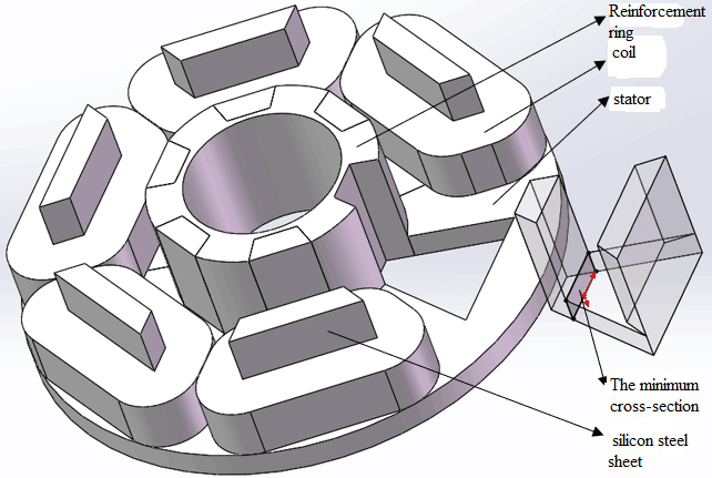
It can be seen from Fig. 1 that, since the laminated six-ring redundant axial magnetic bearing is composed of six silicon steel sheets which have exactly the same structure, we only need to take the structural parameters of one silicon steel sheet as the study object of this paper. Contents shown in Fig. 2 are based on a premise that no interference exists between coils. Since the coil cavity length is
Schematic diagram of size of silicon steel sheet.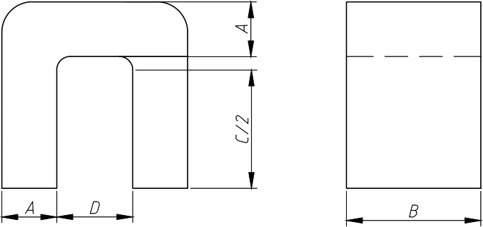
Schematic diagram of cooperation between silicon steel sheet and coil.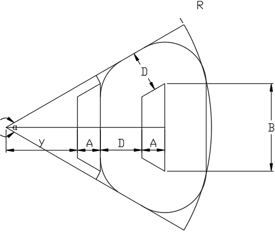
Assuming that certain volume of stator is available, proper
Where:
It can be known from the analysis on magnetic circuit of silicon steel sheets that, the minimum cross-sectional area appeared at the cut corner position, which can be expressed by size of silicon steel sheet as below:
And the objective function is obtained as follow:
Determine constraints:
Magnetic unsaturation constraints:
Coil cavity area constraints:
In Eq. (4):
Magnetic pole area constraint:
Where:
According to the above objective function and constraint conditions, the problem of how to optimize the maximum electromagnetic force under certain volume was solved by MATLAB. Firstly, the mathematical model of the design problem is established according to the prescribed format, and the appropriate optimization algorithm is selected, and the computer program is selected or compiled. Then the optimal design scheme is automatically obtained by computer. The variation curve of the bearing capacity of the magnetic suspension bearing with the area of the magnetic pole and the area of the coil cavity under a certain volume can be obtained, as shown in the Fig. 4. For the initial design conditions and final optimization results, please refer to Tables 1 and 2.
Initial design conditions for redundant axial magnetic bearings
Structural parameters of two types of axial redundant magnetic bearings
Electromagnetic force curve.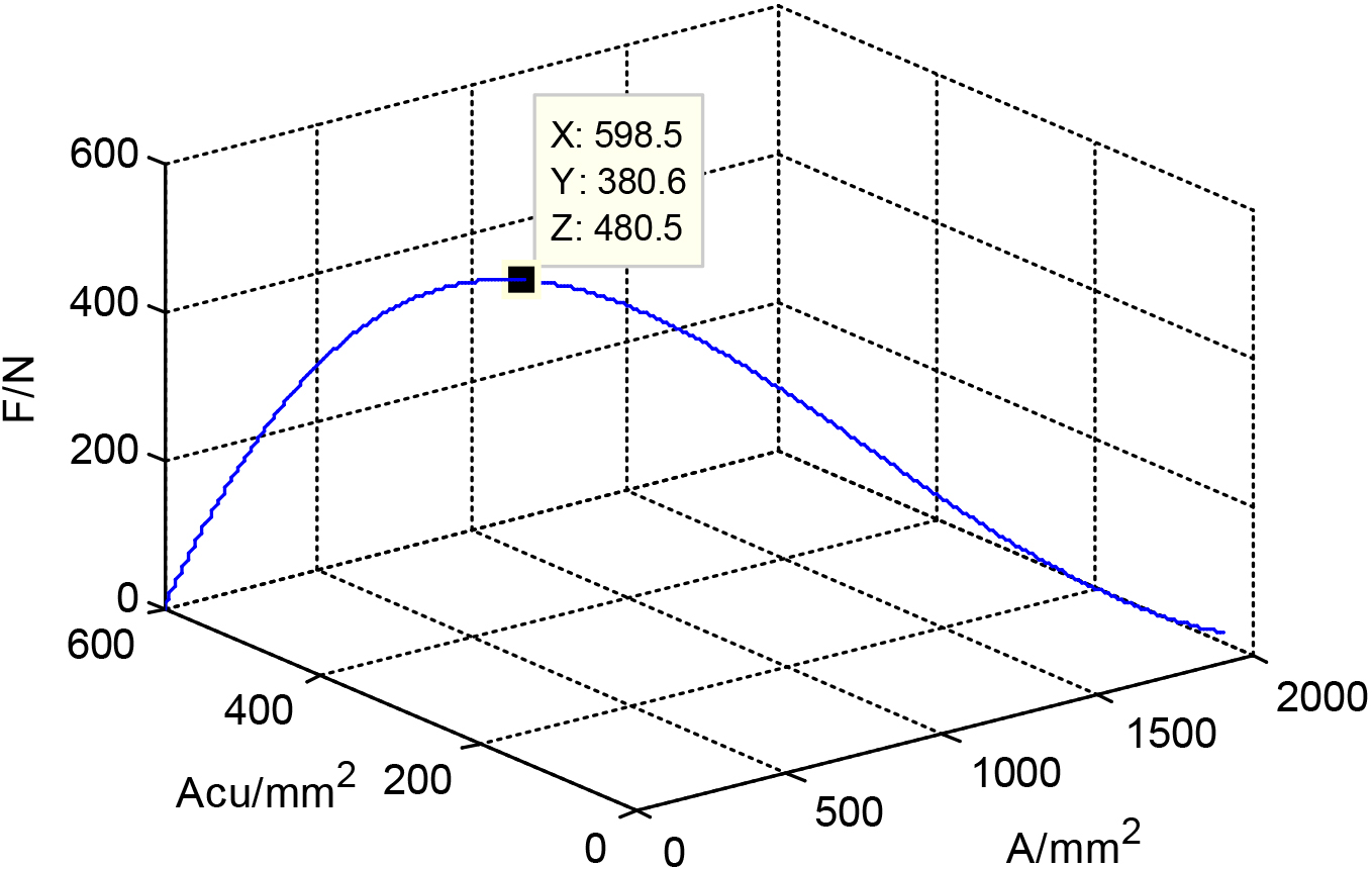
For the laminated structure, different current directions in adjacent coils actually affect the magnetic field distribution and the electromagnetic force of the structure to some certain extent. The electromagnetic force comparison of laminated six-ring structure in different current directions are as shown in Fig. 5. And for the magnetic field distribution of laminated six-ring structure in different current directions, please refer to Fig. 6.
Comparison of electromagnetic force of laminated six-ring structure in different current directions.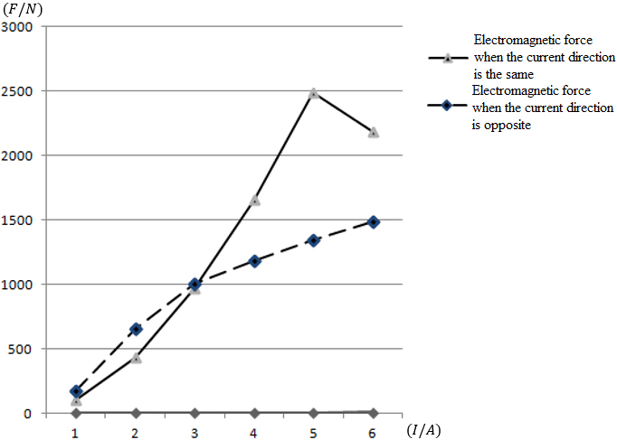
Magnetic field distribution of laminated six-ring structure in different current directions.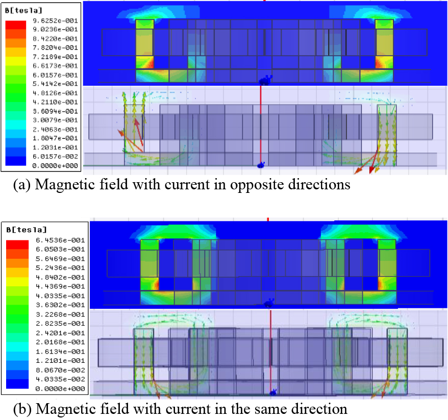
Comparison of magnetic induction intensity of laminated six-ring structure in different current directions
It can be seen from Table 3 that when co-current flows in adjacent coils, the coupling effect of the adjacent silicon steel sheets enhances the magnetic induction intensity on the inner magnetic pole of the single silicon steel sheet and the reinforcing ring to some certain extent. The laminated structure seems to have 6 independent silicon steel sheets working at the same time in parallel collaboration manner. Therefore, the laminated structure is a weak coupling structure. The increases of magnetic induction intensity on inner magnetic pole and reinforcing ring caused by the coupling effect of adjacent silicon steel sheets are not significant. The magnetic induction intensity – B values on both the inner and outer magnetic poles are comparatively even, and not easy to get saturated, so the electromagnetic force could enhance greatly with the current increase.
When the reverse current flows in adjacent coils, the coupling effect of the adjacent silicon steel sheets reduces the magnetic induction intensity on the inner magnetic pole of the single silicon steel sheet and the reinforcing ring, while enhancing the magnetic induction intensity on the outer magnetic pole of the single silicon steel sheet. This leads to comparatively large difference in magnetic induction intensity between inner and outer magnetic poles. Compared to inner magnetic pole, the enhanced outer magnetic pole can easily get saturated, but the magnetic induction intensity on the inner magnetic pole is far from being saturated. Therefore, this kind of electrifying method fails to make good use of the material performance.
In the case that any element in the control loop fails, the compensation currents required for redundant reconfiguration of the system are different, which lead to different requirements on system control hardware for reconfiguration. Therefore, it is necessary to conduct further analysis and research on the mechanical performance of the laminated structure after failure and reconfiguration.
By taking the standard that the electromagnetic force after redundant reconfiguration due to coil failure is no less than the initial electromagnetic force as the criteria, the comparative analysis and research were conducted on balance failure cases. As for the balance failure of laminated six-ring structure, please refer to Fig. 7.
Balance failure of laminated six-ring structure.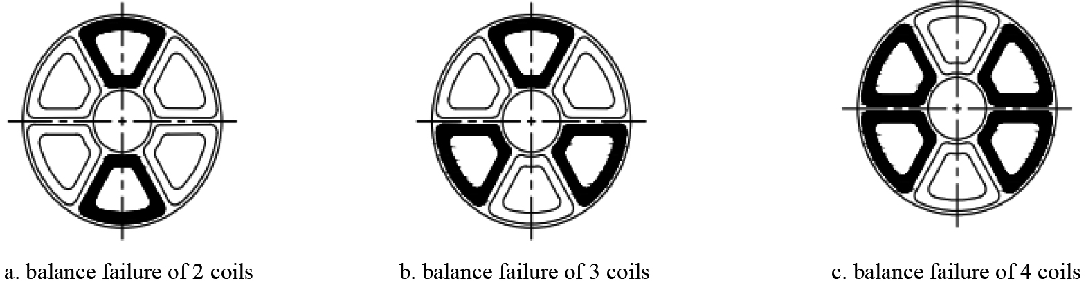
At the condition of having 1A normal working current, as for the failure of a certain element in the control loop (equivalent to coil failure), the laminated six-ring structure could achieve redundant reconfiguration by compensation current. And the sizes of compensation current required by redundant reconfiguration, and the electromagnetic force are as shown in the table.
Comparison of bearing capacity of laminated six-ring structure before and after failure
Redundancy reconfiguration of various balance failures can be achieved under the action of the compensation current. For the laminated six-ring structure, as long as no failure of over three consecutive control loops, the redundancy reconfiguration can be realized under the action of the compensation current. If the laminated six-ring structure fails, in order to resume initial electromagnetic force under the action of compensation current, the compensation current of corresponding failure levels (number of failed coils) should be increased to 15%, 25%, and 50% of the initial current. That is to say, when there are 4 levels of failure, we can just increase 50% of initial current of the laminated structure to resume the electromagnetic force to initial state under the action of compensation current.
The mechanical performance of the electromagnetic force of the laminated six-ring redundant axial magnetic bearing before and after failure has been analyzed, and the redundant feasibility of the laminated six-ring redundant axial magnetic bearing has been analyzed and verified by simulation. In order to verify the accuracy of the above simulation, specific experimental devices were applied in this part to verify the accuracy of the bearing capacity simulation of the laminated six-ring redundant axial magnetic bearing.
The experimental device for the laminated six-ring axial redundant magnetic bearing is mainly composed of the following parts: the overall bracket of the experimental device, the stator part and the rotor part of the laminated six-ring redundant axial magnetic bearing, the counterweight plate, load-bearing rod, the eddy current displacement sensor, the power amplifier, the sensor protective ring, and the Dspace system, etc. The mechanical part of the experimental device is as shown in Fig. 7, while the control part of the experimental device is as shown in Fig. 9.
In Fig. 8, the stator part of the laminated six-ring redundant axial magnetic bearing is composed of six silicon steel sheets with the same volume, size, and interval space along circumference after side cut; each silicon steel sheet is wound with coils of the same number of turns and coil diameter; the bottom of the stator is connected to the counterweight plate by a load-bearing rod; and an eddy current displacement sensor is placed on the bottom end of the counterweight plate and fixed on the sensor bracket, which is used to detect the axial displacement of the stator of the laminated six-ring redundant axial magnetic bearing.
The purpose of putting eddy current displacement sensor under the counterweight plate is to indirectly detect the axial displacement of the stator of the laminated six-ring redundant axial magnetic bearing by detecting the displacement of the counterweight plate, while avoiding the magnetic field interference produced by eddy current displacement sensor to the laminated six-ring redundant axial magnetic bearing at the same time, which would affect the accuracy of the experiment.
Mechanical part of experimental device.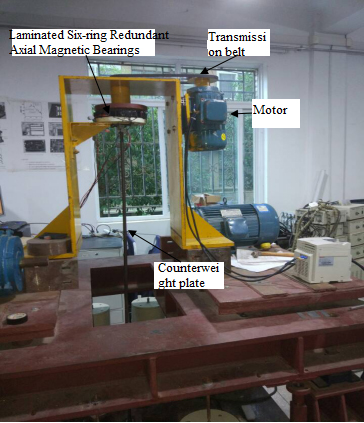
Control part of experimental device.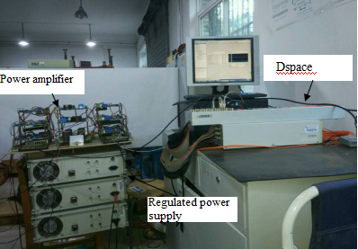
There are six groups of coils distributed on the laminated six-ring redundant axial magnetic suspension bearing. Suppose that each coil independently and normally participates in the suspension operation, we need at least six power amplifiers to control at the same time. Being limited by the number of experimental equipment, and at the same time, in order to fully analyze the normal suspension and the failure of 2 groups of coils, 3 groups of coils, and 4 groups of coils, two methods of control were applied in this experiment: one is to use parallel connecting of interval coils and one power amplifier for control (1
During normal suspension, we set the initial position of the thrust plate at the maximum displacement position deviating from the equilibrium position. By adjusting the PID parameters, the thrust plate rotor is made return to the equilibrium position. As for the curves of the sensor output displacement and time during the suspension process, and the curves of the current and time during the suspension process, please see Fig. 10. When conducting PID adjustment, if the proportional coefficient is small, the vibration of the system during suspension is small; but if the proportional coefficient is large, the vibration during system reconfiguration is also small. Therefore, different proportional coefficients should be selected according to different stages during the suspension reconfiguration process.
Curves of sensor output displacement and time, current and time during suspension process.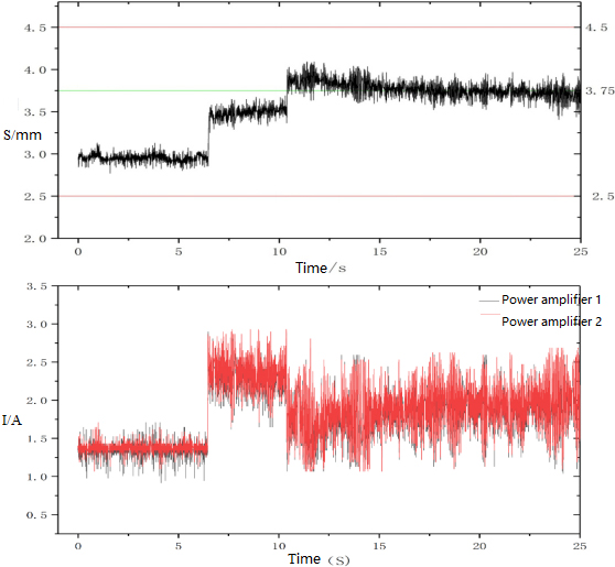
It can be seen from Fig. 9 that, at the time of normal suspension, the laminated structure stator sees a stepped stage at around 6 s during the suspension process, which lasts for about 2.3 s after short time of oscillation, and starts to maintain at a balanced position at around 10 s time and about 3.70 mm position with good stability. It can be seen from the current and time curves that, at the initial suspension stage, the laminated structure suspends properly under the action of the power amplifier, which lasts till about 6 s. With the sharp rise of the current, the laminated structure also has a stepped stage. Then after short time of adjustment, the stator reaches stable suspension state, and the current resumes back to about 2 A stable state.
When building the experiment platform for the laminated redundant axial magnetic bearing, due to the limitations of the experimental equipment and the convenience of structural processing, the optimal structural size was adjusted appropriately in the actual project. According to the current value passed in the coils during normal operation in the actual device, the coil diameter was set as
A 3D model was built up according to the actual size of the laminated six-ring redundant axial magnetic bearing structure, which was then imported into the Workbench to conduct simulation on bearing capacity. The simulation results are as shown in Fig. 11. The bearing capacity simulation result is
Simulation results of laminated structure.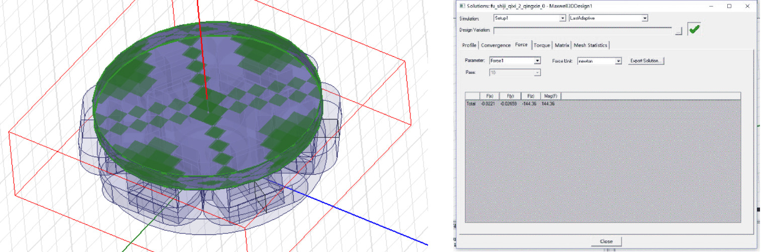
Since the electromagnetic force of and the gravity borne by of the laminated six-ring redundant axial magnetic bearing during stable suspension process are equal to each other, the electromagnetic force of the laminated six-ring redundant axial magnetic bearing during stable suspension can be tested according to gravity borne by the experimental device in Fig. 6A. The borne gravity mainly includes the weight of the silicon steel sheet stator, the weight of the fixing plate of the aluminum silicon steel sheet stator, the weight of the coils (six groups), the weights of the load-bearing rod and the counterweight plate. The mass of each part was measured by a force plate, from which, data were obtained as below: the total weight of the silicon steel stator, the fixing plate of the aluminum silicon steel stator, and the coils (two groups) is approximately
It can be known from the above analysis on the electromagnetic force and simulated electromagnetic force of the laminated six-ring redundant axial magnetic bearing during stable suspension process that, the laminated six-ring redundant axial magnetic bearing can stably suspend under the simulated electromagnetic force, which proves the accuracy of the simulated electromagnetic force.
On the basis of the normal floating and stable operation of the laminated structure, the coils in series face-to-face are disabled, that is, the power amplifiers of the two coils are controlled to fail. The residual four coils are automatically adjusted by the control system to restore the rotor to the equilibrium position. The current curves and displacement curves of the two coils are shown in Fig. 12.
Curves of sensor output displacement and time, current and time during 2 coils fail.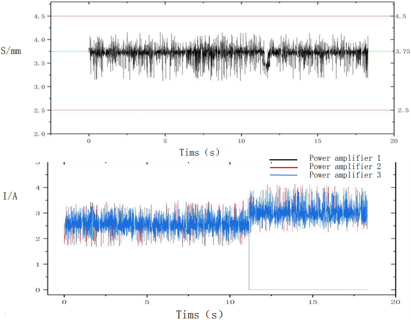
It can be seen from Fig. 7 that the power amplifier 1, 2 and 3 work together in the process of stable suspension. When the suspension time continues to about 11, the two coils controlled by the power amplifier 1 fail, and the current of the instantaneous failure coil decreases from 2.5 to 0. At the same time, the remaining two power amplifiers compensate for the current, and the current increases from 2.5 to about 3. Through a short adjustment, the current is stabilized at around 2.9. At this time, the stacked six-ring redundant axial magnetic bearing is restored to a stable suspension state.
When currents in adjacent coils are flowing in the same direction, the laminated six-ring redundant structure would be featured in weak coupling, and the current direction in adjacent coils would merely affect the magnetic field. In this case, the magnetic induction intensity conditions at the inner and outer magnetic poles are relatively uniform. The reverse current flowing in adjacent coils leads to comparatively large difference in magnetic induction intensity between inner and outer magnetic poles. Compared to inner magnetic pole, the outer magnetic pole can easily get saturated, but the magnetic induction intensity on the inner magnetic pole is far from being saturated. Therefore, this kind of electrifying method fails to make good use of the material performance. As for the laminated six-ring structure, as long as having no failure of over three consecutive control loops (equivalent to coil failure), the redundant reconfiguration is achievable under the action of compensation current. If the laminated six-ring structure fails, in order to resume initial electromagnetic force under the action of compensation current, the compensation current of corresponding failure levels (number of failed coils) should be increased to 15%, 25%, and 50% of the initial current. In the initial stage of the suspension of the laminated structure, the laminated structure sees proper suspension under the action of the current provided by the power amplifier. Then with the sharp rise of current, the laminated structure shows a stepped phase. After a short time of adjustment, the stator suspends stably and the current resumes back to a stable state.