
Abstract
As a high-speed forming technology, electromagnetic forming has been more and more widely used because it can improve the material forming performance greatly. In electromagnetic forming process, the pulsed electromagnetic force generated by the coils is the load of the workpiece, hence its distribution characteristics have a great influence on the workpiece forming performance. Based on the basic principle of electromagnetic forming, this paper introduces and analyzes some latest electromagnetic forming technologies with different coil systems, including electromagnetic incremental forming, space-time-controlled multi-stage pulsed magnetic field forming, and electromagnetic tube expansion with axial compression. Aim at each forming method, the following contents are mainly studied: 1) The key technical problems solved by this method. 2) The structure of the coil system. 3) The distribution of magnetic flux density and electromagnetic force. 4) The advantages and disadvantages of the method. Through above analysis, it is hoped that the basic idea of technological innovation in electromagnetic forming is clarified in this paper, which can provide guidance for the future innovation direction of electromagnetic forming.
Introduction
Electromagnetic forming (EMF) is a high speed forming technology using pulsed high magnetic field to apply electromagnetic force on metallic workpiece [1, 2, 3]. Compared with the conventional processing technology, EMF has two obvious advantages. Firstly, because of high strain rate (10
For development of EMF technology, how to reduce the temperature rise of the coil and how to design a new types of coils with different electromagnetic force distribution for deforming workpiece should be seriously focused [7, 8, 9]. In EMF process, coil system is the actuation of electromagnetic force, whose structure affects the distribution of electromagnetic field and force directly. Psyk et al. point out that the coil system should have high energy conversion efficiency, high mechanical strength, and optimized discharge pulse width [10]. According to the actual workpiece surface characteristics, Tekkaya et al. design a coil system to match the workpiece structure for the improvement of the EMF energy conversion efficiency [11]. Qiu et al. introduce the pulsed high magnetic field technology to EMF, result in the coil mechanical strength and the electromagnetic force generated by the coil system are obviously increased [12]. Cao et al. research the effects of current frequency on the electromagnetic sheet forming process, the obtained results show that the optimal current frequency is related to the relative skin depth of the workpiece, and find that there are two better current frequencies for different relative skin depth [13]. Kamal proposes a new coil system named uniform pressure electromagnetic actuator, which can produce relatively uniform electromagnetic force in the workpiece [14]. A U-shaped external conductor is required to form a closed secondary circuit with the workpiece in uniform pressure electromagnetic forming process. The above studies have solved some basic technical problems in EMF, hence the applications of new coil system with special electromagnetic force distribution should be noted for development of EMF technology.
The rest of the paper is arranged as the following. Section 2 presents the basic principle of EMF process. Sections 3–5 present the three typical technology respectively. Section 6 concludes this paper.
Basic principle
EMF equipment mainly includes charging system, capacitor, discharge switch, coil system, and workpiece, as shown in Fig. 1. Firstly, the capacitor is charged by the charging system. Secondly, the stored energy is loaded into the coil system through the discharge switch to generate a pulse large current and a pulse strong magnetic field around the workpiece. Thirdly, the variational magnetic field produces induced eddy current in the workpiece. Finally, the electromagnetic force between the pulse current in the coil system and the induced eddy current in the workpiece drives the workpiece instantly accelerated and deformed [15]. Usually, EMF is divided into electromagnetic tube forming and electromagnetic sheet forming [16, 17, 18]. According to the different workpiece geometric structure, the tube is deformed by using helix coil system in EMF process, while the sheet is deformed by using spiral coil system.
Diagram of EMF equipment. (a) basic principle, (b) electromagnetic tube forming, (c) electromagnetic sheet forming.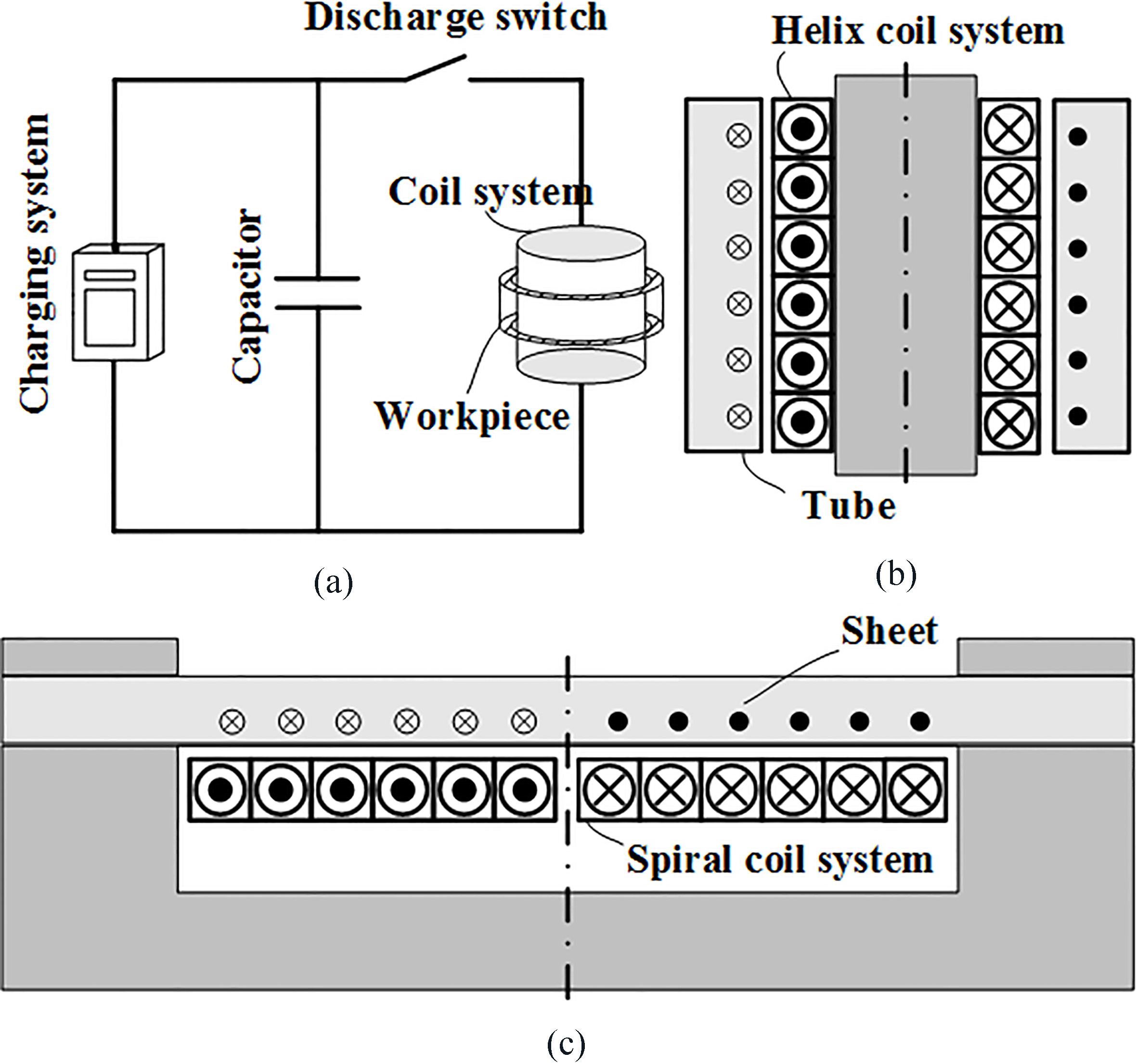
Magnetic flux density and electromagnetic fore in electromagnetic sheet forming process.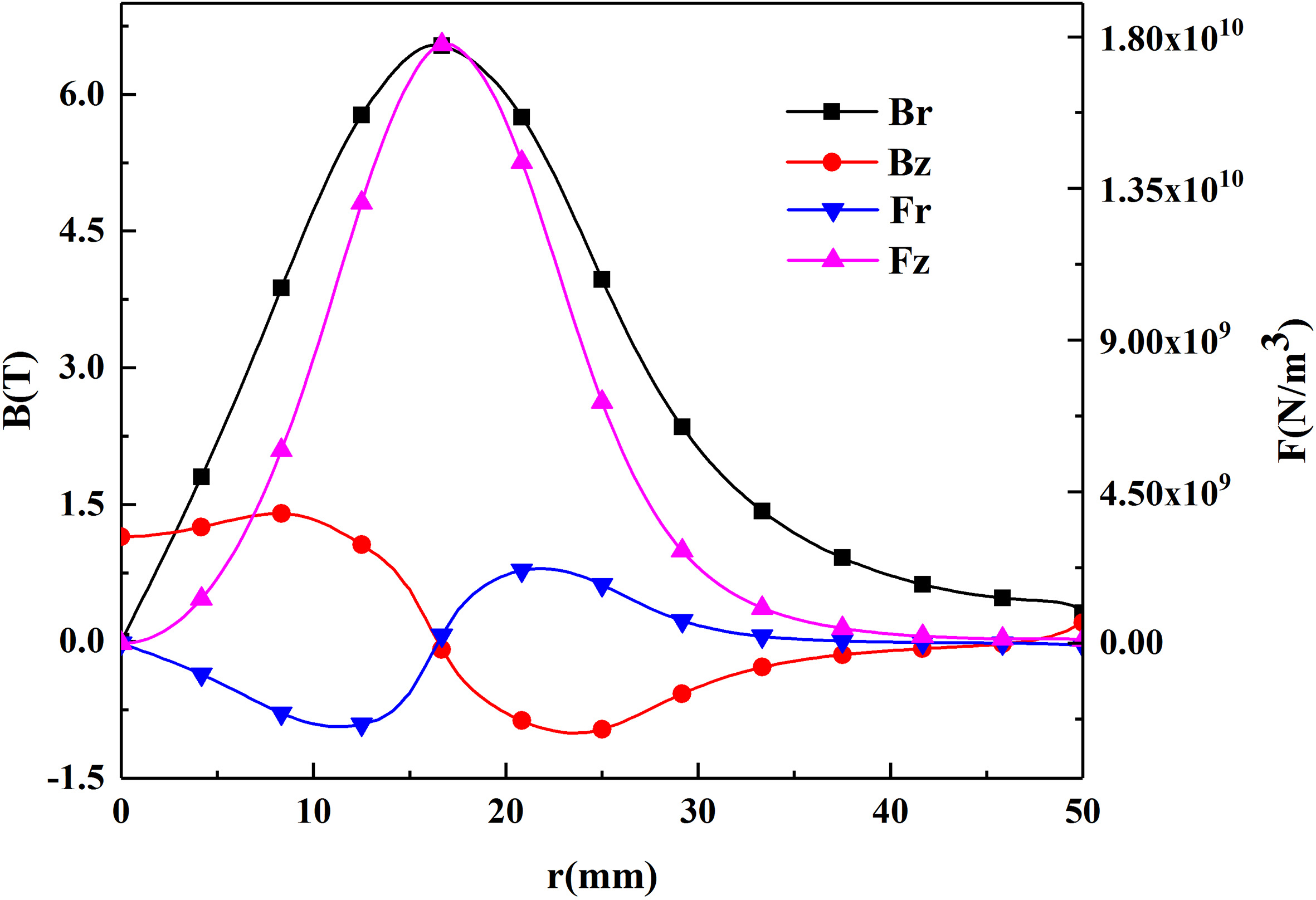
Ignoring the influence of the asymptotic line, spiral coil system and helix coil system can be equivalent to a plurality of radially distributed closed rings and axially distributed closed rings respectively. And then, the coil system, the workpiece, and the electromagnetic field source are all axial symmetrical, hence it can be simplified as a two-dimensional axisymmetric model. The eddy current in the workpiece mainly flows in the hoop direction:
Where
The electromagnetic force acting on the workpiece is determined by both the induced eddy current and the magnetic flux density:
Figures 2 and 3 show that the electromagnetic force acting on a sheet is mainly in the axial direction Eq. (4), while that acting on a tube is mainly in the radial direction Eq. (5). It is clear that the electromagnetic force is related to the magnetic flux density, whose distribution mainly depends on the geometric structure of the coil system.
Magnetic flux density and electromagnetic fore in electromagnetic tube forming process.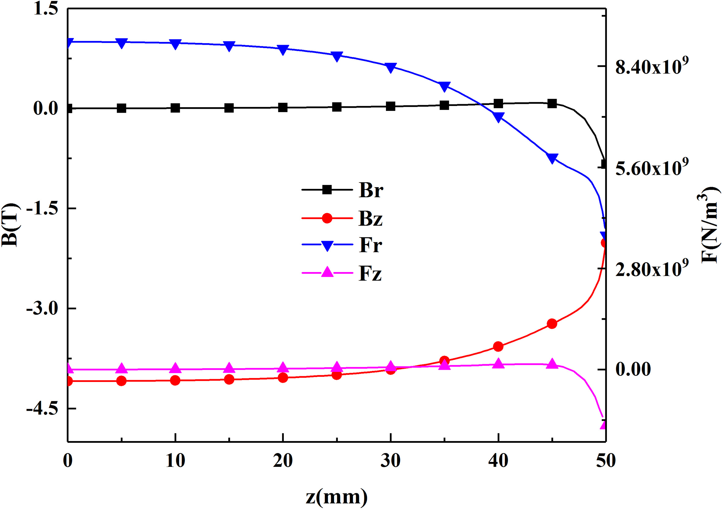
In electromagnetic sheet forming process, the workpiece is located at one side of the spiral coil system, and the magnetic flux density in this region is extremely uneven, resulting in a uneven distribution of electromagnetic force, as shown in Fig. 2. In electromagnetic tube forming process, the workpiece is located outside or inside the helix coil system, the electromagnetic force is relatively uniform because of the axial symmetry, as shown in Fig. 3.
In conventional electromagnetic sheet forming process, it is difficult to deform large-scale sheet due to the limit of the power capacity and coil geometry size. Combining EMF with digital control, Mo et al. propose a new technology named electromagnetic incremental forming [19]. Figure 4 shows the basic principle of electromagnetic incremental forming. Firstly, a small coil is used to generate local electromagnetic force and deform part of large-scale sheet, and then the large-scale sheet is completely deformed by moving the coil system with computer control.
Principle of Electromagnetic incremental forming.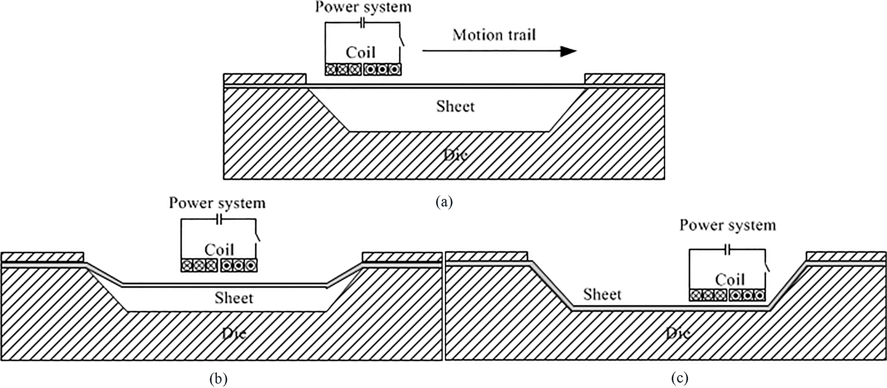
Deformed sheet using Electromagnetic incremental forming. (a) loading path, (b) deformed sheet with 1600 V voltage, (c) deformed sheet with 1600 V 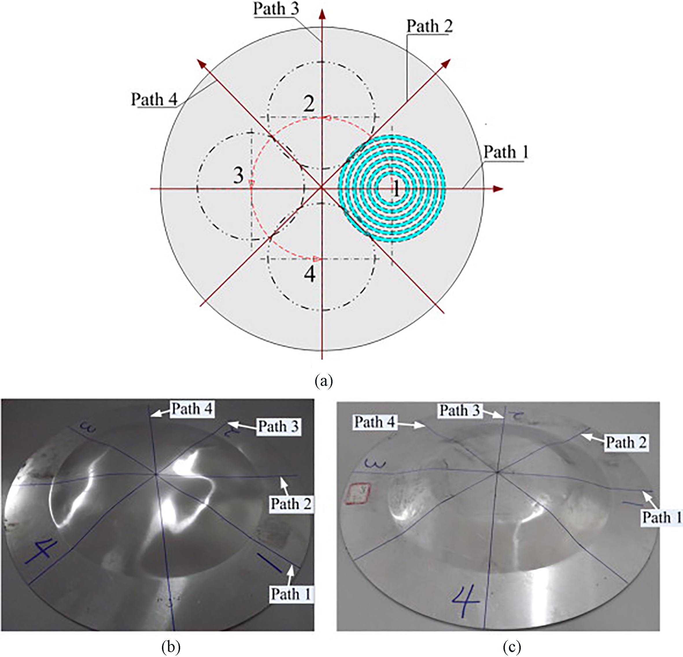
By use of electromagnetic incremental forming, a spiral coil system with inner radius, outer radius, and height of 12 mm, 48 mm, 6 mm respectively is used to deform an AA3003 sheet with a diameter of 280 mm and a thickness of 1 mm [20]. The coil is firstly discharged at 60 mm away from the middle of workpiece, and then it is moved along the loading path as shown in Fig. 5a. Figure 5b shows the deformed sheet by electromagnetic incremental forming. The results show that the sheet has a good moldability with the side surface of the die. It is verified that electromagnetic incremental forming is feasibly to produce a large part with small coil and small discharge energy. However, the workpiece is mainly bulged but slightly flowed in electromagnetic incremental forming process.
Principle of axial-radial force bi-directionally loaded in double coil electromagnetic forming [22].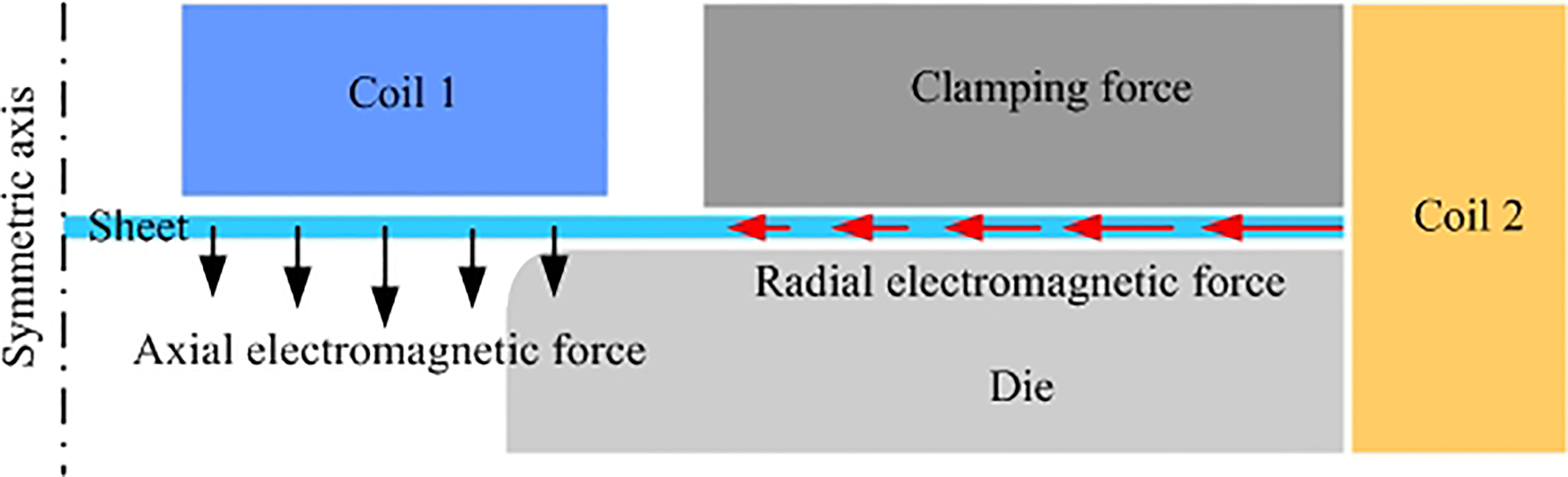
Simulation and experimental results of EMF with double coils for deep drawing. (a) simulation, (b) experiment [23].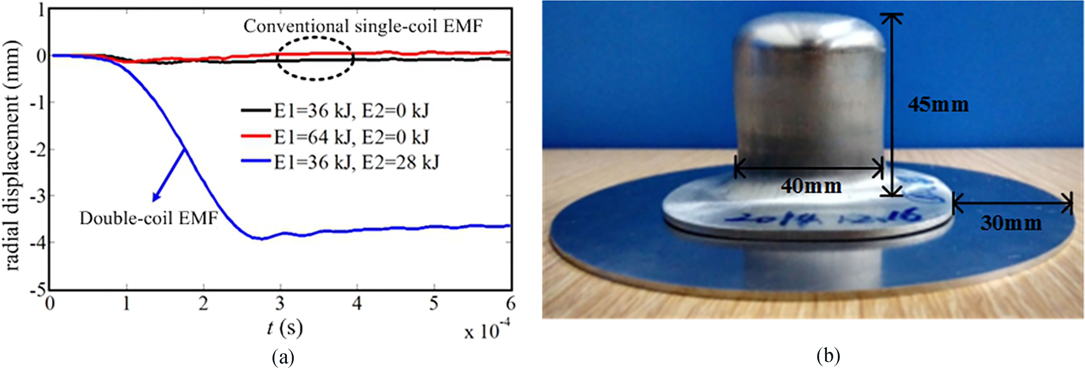
To increase the deformation depth, Li et al. propose a method named space-time-controlled multi-Stage pulsed magnetic field forming [21]. Multiple sets of coils with the corresponding power supply are applied to provide a wider space and a longer period of electromagnetic force for workpiece.
A practical application of space-time-controlled multi-stage pulsed magnetic field forming is loading both the axial and radial electromagnetic force on sheet for deep drawing [22, 23]. On the basis of a conventional single-coil EMF (coil 1), a coil system (coil 2) is introduced at the outside of the sheet, as shown in Fig. 6. Coil 1 mainly provides the axial electromagnetic force, while coil 2 mainly provides the radial electromagnetic force. Because of the radial electromagnetic force in the flange of the sheet, the material flow property is increased effectively. Figure 7 shows the simulation and experimental results of EMF with double coils for deep drawing. The results show that the radial displacement of the workpiece in the conventional single-coil EMF is limited, but there is obvious plastic flow when the radial electromagnetic force is introduced. On the whole, space-time-controlled multi-stage pulsed magnetic field forming can enhance the material plastic flow by using multiple sets of coils. But the price is also increased due to the large investment of equipment.
Electromagnetic tube expansion with axial compression
Electromagnetic tube forming can be divided into tube expansion and tube compression. In conventional electromagnetic tube expansion process, the electromagnetic force generated by helix coil system is mainly in the radial direction. And then the wall thickness and the strength of the tube are reduced with the increasing of the radius during the workpiece deformed. As a result, it is difficult to meet the requirement of modern industry for high strength and performance parts.
Coil system. (a) conventional electromagnetic tube expansion, (b) electromagnetic tube expansion with axial compression.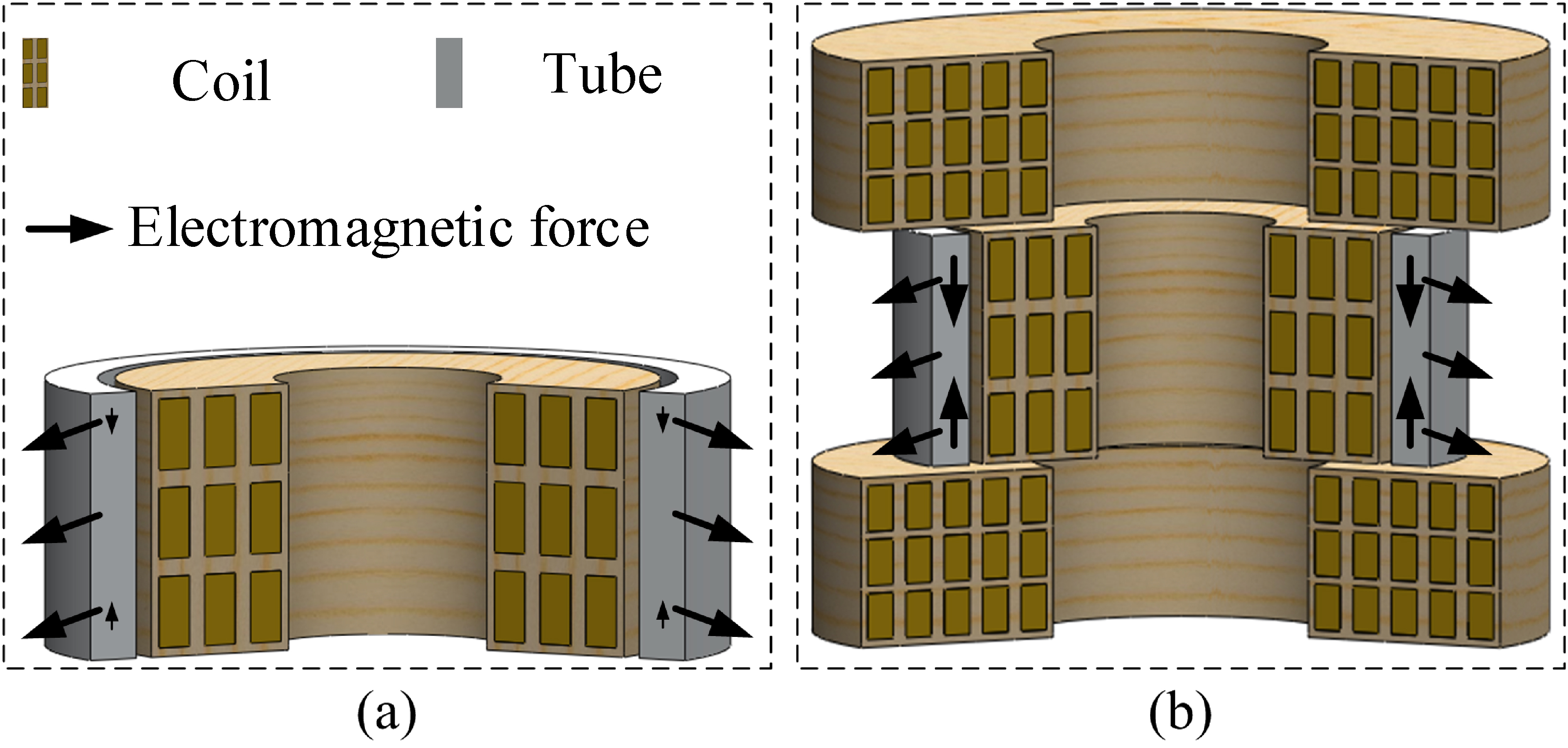
In order to solve this problem, electromagnetic tube expansion with axial compression is proposed by Qiu et al. Figure 8 shows the structure of coil system in this method. Firstly, the axial and the radial magnetic flux density are generated in the workpiece region by the coil system. Secondly, the radial electromagnetic force is generated by the interaction between the eddy current and the axial magnetic flux density, and the axial electromagnetic force is simultaneously generated by the interaction between the eddy current and the radial magnetic flux density. Finally, the radial electromagnetic force expands the workpiece in the radial direction, while the axial electromagnetic force compresses the workpiece in the axial direction. In this method, the reduction of wall thickness of the workpiece can be effectively decreased and the workpiece deformation performance is improved due to the axial compression.
Axial electromagnetic force and thickness of the deformed tube. (a) force, (b) thickness.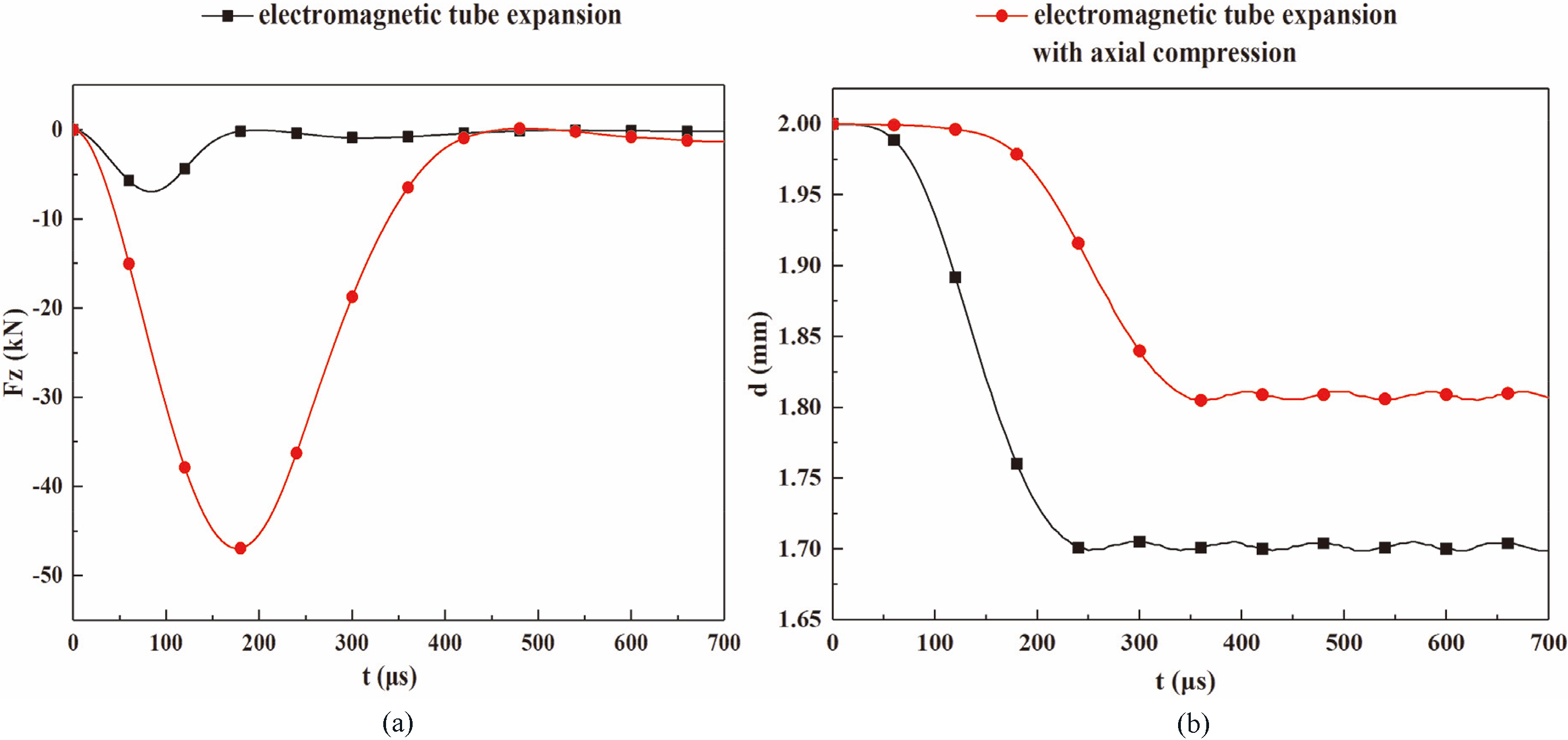
Figure 9 shows the axial electromagnetic force and the thickness of the tube when using conventional electromagnetic tube expansion and electromagnetic tube expansion with axial compression respectively. The workpiece is AA1060 tube with a diameter of 100 mm and a wall thickness of 2 mm. a helix coil system with inner radius, outer radius, and height of 45 mm, 48 mm, 20 mm respectively is used to expand the workpiece, while another coil system with inner radius, outer radius, and height of 46 mm, 52 mm, 15 mm respectively is used to generate the axial electromagnetic force for axial compression. Under the same expansion depth, it is observed that the axial electromagnetic force generated by electromagnetic tube expansion with axial compression is 6.747 times of that generated by the conventional electromagnetic tube expansion. Furthermore, because of the increase of the axial electromagnetic force, the material flow property is increased in the axial direction, and then the reduction of wall thickness is reduced from 15.05% to 9.65%.
Electromagnetic incremental forming, space-time-controlled multi-stage pulsed magnetic field forming, and electromagnetic tube expansion with axial compression have been discussed in this paper. In general, each new method can solve some problems in conventional EMF process, and promote EMF for development. However, some key technical issues in EMF should be solved for achieving industrialized application. One issue is how to design the corresponding coil system according to the specific forming requirements. Another one is how to solve the temperature problem in the coil system caused by the large current. EMF should been widely used in light alloy forming in the future.
Footnotes
Acknowledgments
This work is supported by the National Natural Science Foundation of China (51507092, 51707104) and State Key Laboratory of Advanced Electromagnetic Engineering and Technology (Huazhong University of Science and Technology), and sponsored by Research Fund for Excellent Dissertation of China Three Gorges University (2018SSPY060). The authors thank Bairong Song from School of Foreign Languages, China Three Gorges University for her language translating work and Alan Treworgy from Lewiston, Maine, USA, for his language revision advice.