



Abstract
The automation transformation of container lifting operations is one of the main technical issues in Rail-Truck intermodal transportation. To solve this problem, this paper analyzes the advantages and disadvantages of several existing container positioning methods, and proposed a container corner holes location detection method based on lightweight convolutional neural network and adaptive morphological image processing algorithm. This method locates the container through a visual sensor that shoots from top to bottom. In order to improve the positioning accuracy and calculation speed while maintaining a high recognition rate, this method first uses a lightweight SSD detector to quickly detect the rough coordinates of the container corner hole in the image. On this basis, the smallest rectangle detection method based on adaptive HSV filtering is used to detect the precise coordinates of the corner hole in the image. Experiments show that the recognition rate of this algorithm in the initial positioning process reaches 94.2%, the recognition rate of secondary positioning reaches 87.4%, and the final positioning error is lower than 3.765 pixels and 2.81 pixels in the heading and lateral directions, respectively. The overall calculation time of the algorithm can realize the positioning calculation of 30 frames per second, which shows that this method takes into account the characteristics of high measurement accuracy and high calculation speed on the basis of high recognition rate.
Keywords
Introduction
Container transport is a transportation service with standard containers as carriers, and it is a basic mode of intermodal transportation. The uniform transportation standard enables containers to transport goods in a variety of different transportation modes without the need to pack or unpack when changing the transportation mode. Rail-Truck intermodal transportation is an important inland container transport mode. It uses rail transportation to transport a large number of containers over long distances and uses trucks to freight containers in the local area. China has a huge territory and a railway network that goes through the whole country, which provides convenient conditions for the development of the Rail-Truck intermodal transportation [1].
In the process of rail-truck intermodal transportation, container lifting equipment such as gantry cranes and reach stackers are needed to transfer containers between yards, trains and container trucks, which is called container lifting operation. Considering that the handling and alignment of tens of tons of containers are involved in the lifting process, the container hoisting operation is a job with high precision and safety requirements. Take the hoisting operation of a gantry crane as an example. During the operation, the driver of the gantry crane will control the spreader to descend, align with the container in the manner shown in Fig. 1, and finally lift it. Generally, a lifting process of a container takes about 30 seconds, of which about 15 seconds is the docking adjustment time. This is because the gantry crane cab is located at the height of the equipment, and it is not convenient to observe the relative position of the spreader and the container. It is often necessary to adjust the position of the spreader repeatedly during alignment, which reduces the work efficiency.
Spreader alignment operation.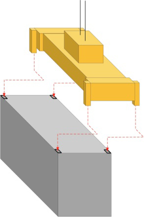
In order to improve the efficiency of the operation, it is considered feasible to introduce automatic measuring equipment to assist the operation of lifting equipment. In the past, the container positioning method was mainly based on laser scanner [2]. This type of solution uses the container attitude data collected by lidar to locate the container. Using laser as a tool to collect data can meet the needs of all-weather operations, which is particularly important in a container transfer environment where stable light cannot be guaranteed. However, the laser scanner has the problems of high cost and difficult installation. For example, in the positioning task of a gantry crane, the most suitable installation location for lidar is the beam of the gantry crane, but the beam is far from the container on the ground, and the lidar equipment that can achieve precise positioning at this distance is relatively expensive. If the radar is installed on the legs of the gantry crane, the equipment will have a measurement blind angle due to the narrow field of view. These problems make lidar scheme have limits.
With the development of vision technology, the measurement equipment of vision measurement technology has gradually been used in the field of industrial measurement due to its high accuracy and easy installation of acquisition equipment. Now this type of technology has also been widely used in the automation of railway container yards [3]. However, there are also some problems in visual measurement technology. The first step of using visual measurement to obtain the position of the target in the image is to identify the characteristics of the target and filter out the invalid information in the image. Considering that the station environment has the characteristics of unstable illumination and easy fouling of equipment, this poses a challenge to quickly and effectively locate the container. As an example, Chen et al. [4] proposed a container positioning method based on feature matching, but its recognition rate was only 91.2%, and the calculation time reached 280 ms. Dai et al. [5] proposed a method of using images to locate containers in the cabin, but in order to extract container information from a complex environment, this method performed a lot of calculations on the entire image, making the calculation time for a single photo reach 0.6 s, unable to meet real-time requirements. Li and Fang [6] proposed a container corner hole detection and location method based on HOG features and Support Vector Machine (SVM), which achieved a recognition success rate of 92%, but its calculation time reached 0.5 s. High-precision positioning data requires high-resolution image support, while traditional morphological image processing methods require a large amount of computing power, and it is difficult to achieve real-time requirements when processing high-resolution images.
The feature recognition technology of convolutional neural network has been widely used in the field of industrial measurement due to its stronger robustness and faster calculation speed [7, 8]. However, the IOU detection frame design of the neural network makes the positioning accuracy relatively insufficient. Kitayama et al. [9] applied the container corner hole recognition method based on the SSD neural network. In this paper, the recognition success rate of the neural network reached 94.57%. The identified IOU only reached 87.79%, making the accuracy of this measurement method still low.
Based on the above research, this paper proposes a container corner hole recognition technology that combines neural network and adaptive morphological processing methods to quickly and accurately measure the position of the container corner hole while maintaining the recognition rate. This method first uses neural network detection to remove a large amount of irrelevant information in the image, then locks out a small image area with corner hole features, and uses a fast secondary detection based on adaptive HSV filtering and morphological calculation algorithms to improve detection accuracy. This paper organized as follows. Section 1 introduces the measurement system, Section 2 introduces the measurement algorithm, Section 3 is the experiment and discussion, and Section 4 is the conclusion.
This system mainly solves the problem of real-time measurement of the relative position of the container and the lifting equipment in the container lifting operation. The spreader alignment operation requires the position information of the container on the horizontal plane. The system uses a camera installed on the main beam of the hoisting equipment to take pictures from top to bottom, and collect pictures with information on the horizontal position of the container. The data collected by the image acquisition equipment is sent to the image processing equipment in the RMG electrical room. This data is used to calculate container locations. The calculation results will be sent to the RMG control system.
The installation position of the cameras is shown in Fig. 2. Two sets of cameras are installed on the lifting equipment beams above the two ends of the RMG truck track to avoid the movement route of the spreader in the center of the RMG. In some studies, cameras are installed on the spreader, but the shaking of the spreader during the movement and lifting process will cause the camera to produce additional positioning errors, so this installation method is not suitable for this design [10]. And because the field of view of a single camera is limited and can only cover half of the working area, the system sets up two cameras to shoot the front and rear of the container respectively.
Installation of cameras.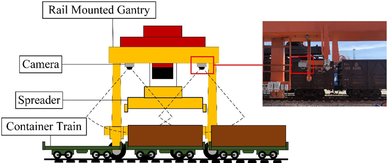
Positioning system structure.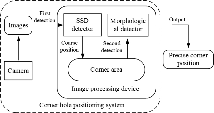
The processing flow of the lock positioning algorithm is shown in Fig. 3. First, the neural network is used to locate the rough position of the container corner hole in the image, and determine the area containing the corner hole in the image. In this area, morphological methods are used to detect the precise position of the corner hole.
The positioning problem of the container can be simplified as the positioning problem of the characteristic area on the container. Here, the corner hole area on the upper surface of the container is selected as the characteristic point to be identified. The positions of the characteristic on the container are shown in the red box in Fig. 4.
Corner holes on the container.
The detection link of container positioning operation requires high real-time performance. Considering that the equipment is still in motion during the positioning process, and the detection algorithm uses the container position at the time of image input as the positioning result. Therefore, the calculation time of the algorithm is too long, which will cause an inevitable offset between the positioning result and the actual position.
In order to achieve a faster recognition speed, this paper uses a lightweight SSD (Single Shot MultiBox Detector) detector to initially locate the corner hole target in the image [11]. SSD is a neural network model based on the convolutional layer of VGG-16 [12]. On the basis of the VGG convolutional layer, it adds several feature layers with different receptive field scales to detect and classify target objects. In order to further optimize the detection performance of SSD, we made the following optimizations to the neural network model.
(1) Convolutional layer optimization
A large number of weight parameters are introduced in the calculation process of the neural network, which makes the convolution calculation very time-consuming. If a larger convolution filter is decomposed into several smaller convolution filters, the parameter amount of the convolution calculation can be effectively reduced, thereby increasing the calculation speed. For example, for a
The above convolution filter can be replaced by a combination of a 1*1
The original SSD uses VGG-16 as the basic convolution layer, which is divided into 5 stages as shown in the figure, and each stage contains three 3*3 convolution operations. Among them, stage4 and stage5 contain more convolution weight parameter sets because of the large number of input channels, so we use the method proposed above to change the convolution filter combination. The convolution filter parameters used by the original VGG in stage4 and stage5 are 3*3*512, which are modified in this article to 1*1*256, 3*3*256, 1*1*512, as it is shown in the Fig. 5.
Light-weighted change.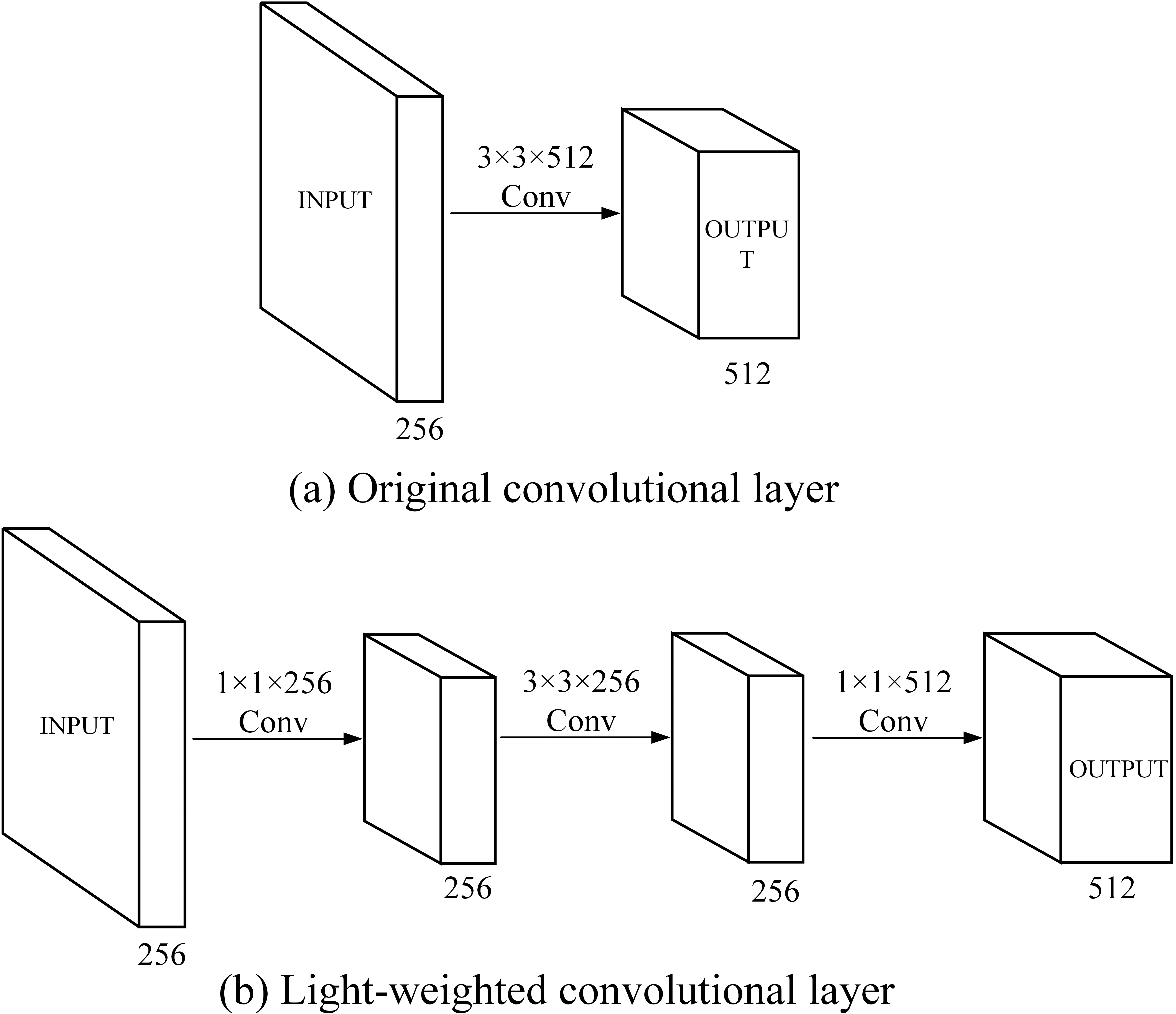
(2) Optimization of anchor box ratio
SSD uses a series of anchor boxes of different sizes and different aspect ratios as the prior regions for target recognition tasks, and its significance is to provide a priori template reference for feature recognition in the process of neural network training and detection. This design has been applied in many neural network models. The test object for the anchor box adaptation of the original SSD is the VOC2007 data set. Except for the first and last layers of the feature layer, each feature layer is equipped with five groups of anchor boxes with an aspect ratio of [1:1, 1:2, 2:1, 1:3, 3:1] to adapt to different objects. For any other recognition target, the ideal aspect ratio of the anchor frame should match the scale aspect ratio of the recognition target in the image. This paper is based on the K-means cluster analysis method to calculate the best anchor box aspect ratio of the corner hole feature. Figure 6 shows the K-means clustering data distribution calculated from the corner hole feature. The corner hole image data comes from the container data set collected by the camera arranged in Chapter 2, from which the recommended Anchor aspect ratio is about [1:1.7]. It should be noted that the image data should be normalized before the cluster analysis to match the network input image size of the SSD.
K-means cluster analysis of corner hole aspect ratio.
Typical detection results of CNN detector.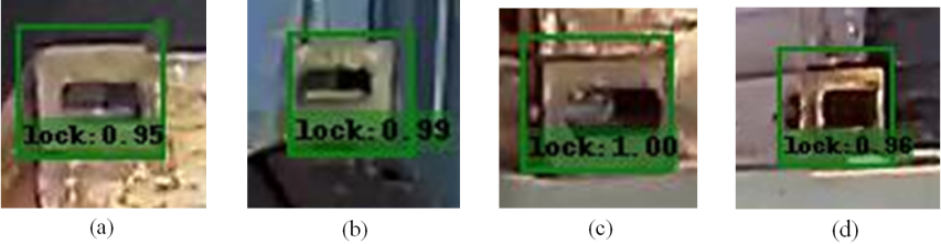
Since the principle of the current mainstream convolutional neural network detector is based on the recognition and classification of features. The detection result is the area where the target to be recognized is most likely to exist in the image, which makes its positioning accuracy less than ideal situation [13]. A typical situation is shown in Fig. 7. For example, the positioning accuracy of a convolutional neural network is often based on the ratio of the overlap area between the detection frame and the feature frame (Intersection over union, IOU). The average score (mean Average Precision, mAP) of the original SSD on PASCAL VOC2007 is only 72.1 %. The traditional morphological method uses pixels as the basic unit to obtain higher positioning accuracy.
Before the second detection, in order to ensure that the detection result contains a complete corner hole image, it is necessary to appropriately expand the detection result range of the preliminary positioning. Assuming that the corner hole position information obtained through neural network detection is
The second inspection link is divided into two stages. First, by preprocessing the image, get the edge contour information of the corner hole feature from the original image, and then use the morphological method to detect the corner hole feature in the image.
The image preprocessing flow is shown in Fig. 8. In the actual operating environment, the color and pollution of the container and the unstable light environment of the transfer station will cause a lot of interference to the identification operation. In order to eliminate these interferences, the first step of image preprocessing is to use an adaptive binarization method based on HSV color space to separate the dark area contours in the image [14]. Because the HSV threshold is more in line with the human eye’s perception of color, it can better reflect the features in the image [15]. The corner hole target is often located in the shadow area of the image, and the brightness V space in the HSV color space can eliminate the interference of color, and calculate the brightness information of the pixel separately to separate the target. The calculation method of HSV binarization is shown in Eq. (2), Among them,
Image pre-processing.
Corner hole detection process.
The second step of the image preprocessing process is the corrosion and expansion of the image, which is used to remove the noise in the image and retain a relatively intact corner hole area. The last step is to use the Canny operator to extract the contours in the image [16]. After preprocessing, most of the interference information in the picture has been eliminated, and a relatively intact corner hole core area is retained. This kind of image can be used for subsequent corner hole detection.
Due to the interference of ambient light, the contour of the corner hole shown in the pre-processed image is often irregular and missing closed graphics. The corner hole detection process is used to solve the identification problems of these corner hole features with different shapes and missing degrees, and the algorithm flow is shown in Fig. 9.
The first step is to detect the closed contours present in the contour image and extract the position point set
The second step is to calculate the minimum bounding rectangle of
The calculation of the minimum bounding rectangle is divided into two steps:
The first is to use the convex hull algorithm to find the convex hull point set in the corner hole contour image. Take the corner hole contour in Fig. 9 as an example, as shown in Fig. 10a. Establish a coordinate axis for the corner hole contour image and determine the point
Minimum rectangle fitting.
After the convex hull boundary of the corner hole is obtained, the minimum circumscribed rectangle can be obtained by boundary rotation, as shown in Fig. 10b. Firstly, find the maximum and minimum points of the abscissa and ordinate in the point set
The experimental part is divided into two parts: the detection performance test of the neural network and the detection performance test of the image processing algorithm. The performance parameters and system configuration of the test platform are shown in Table 1. The performance level is similar to the common industrial personal computer.
Test platform configuration
Test platform configuration
The actual size of the corner hole is about 125 mm in length and 64 mm in width according to ISO 1161:2016 (Series 1 freight containers Corner and intermediate fittings Specifications). In order to meet the operating requirements, the spreader lock can be inserted into the container lock hole when the spreader is aligned, the positioning algorithm needs to ensure the lateral positioning error within 20 mm and the heading positioning error within 40 mm (Taking into account the manufacturing errors of the corner hole and the spreader itself, as well as the deformation of the box, the deflection of the spreader, etc.).
The training of the neural network used 8000 images of the top surface of the container with the position of the corner hole marked. The neural network model is built in the Pytorch environment, and the initial learning rate is
The evaluation of the SSD detector is divided into two parts. The first part is to compare the performance indicators of the SSD detector before and after the weight reduction, and compare its single target detection accuracy value AP. The test results are shown in Table 2.
Performance of neural network detectors
Performance of neural network detectors
In order to establish the conversion model between the pixel distance and the real distance, we first use the Zhang Zhengyou method [17] to convert the image with distortion effect into an image similar to the effect of pinhole imaging before experimenting. In the pinhole imaging principle, the pixel distance and the real distance are considered to be linear.
The second part of the test is to calculate the positioning error of the modified neural network. The results are shown in Table 3. The confidence interval data is calculated by the following process: First, in the MATLAB environment, draw a scatter diagram of the relative distance of the detection results from the standard center in the horizontal and vertical directions of the image. Then fit the normal distribution curve through the scatter plot. Calculate the maximum error value within the 95% and 90% probability interval of the fitted normal distribution curve Maximum error value of the error distribution curve after normal fitting under the confidence interval.
The image coordinate unit in the detection result is pixels, and the millimeter unit data in the table is the value calculated by fitting the size of the corner hole area on the image to the actual corner hole size.
Positioning accuracy of lightweight SSD
Experimental results show that the SSD detector has a faster calculation speed and a higher recognition rate, and the measurement error level within the 95% confidence interval still cannot meet the needs of the job. On the other hand, the calculation speed of the optimized algorithm is increased by about 19.2%, leaving sufficient calculation time for the next step of morphological detection.
The realization of the morphological detection algorithm is based on the OpenCV function library in the Python environment [18]. The experiment uses 500 corner hole samples taken at different time periods, and the average image size is about 80*60 pixels. The detection results of some morphological detection images are shown in Fig. 11. Table 4 records the detection error statistical results after normal fitting.
Test results of morphological detector.
Morphology detection algorithm performance
The experimental results show that the method of detecting the corner hole using the method of finding the minimum circumscribed rectangle has high positioning accuracy, which is sufficient to meet the positioning accuracy requirements of container hoisting operations in the vision system scheme constructed in this paper. However, its recognition rate still has a large gap compared with convolutional neural networks. The reason is that the light interference in the actual operation scene will produce shadow areas on the upper surface of the container, which will interfere with the calculation of the morphological detection algorithm. On the other hand, the calculation speed of the secondary detection algorithm is relatively high. This is mainly due to the fact that the neural network has filtered most of the irrelevant areas in the image from the picture, reducing the size of the picture actually involved in the image operation.
In addition, due to the low detection rate of the morphological algorithm, it is inevitable that the neural network detector has completed the detection but the morphological detection algorithm cannot detect it. The detection failure of the morphological algorithm usually manifests itself as being too far away from the target. To cope with this situation, we design a probabilistic judgment mechanism to judge the reliability of the detection results in the primary and secondary detection results. When the mechanism judges that the morphological algorithm detection fails, the neural network detection result will be used instead.
Aiming at the problem of automatic positioning of container hoisting operations, this paper proposes a vision-based container corner hole detection system. The system provides accurate container parameters for container hoisting operations by detecting the position of the lock hole on the upper surface of the container in the screen. Experimental results show that, compared with single SSD detection, the introduction of morphology-based secondary detection method reduces the error value by about half. However, due to the optimization of the calculation speed of the SSD detector, the overall inspection time is the same as the single inspection performed with the SSD before the optimization. The results prove that the method proposed in this paper takes into account the calculation speed and higher measurement accuracy on the basis of high recognition rate.
Footnotes
Acknowledgments
This research was supported by the Science and Technology Commission of Shanghai Municipality (No. 22ZR1427700), China (Shanghai) Pilot Free Trade Zone Lin-gang Special Area Administration (No. SH-LG-GK-2020-21). We appreciated Shanghai SMUVision Smart Technology Ltd about the data sharing in this research work.