
Abstract
In view of the current new energy vehicles only implement torque control on the drive motor, resulting in the engine speed fluctuation, affecting the vehicle running stability and reducing the engine efficiency and energy saving effect, a new energy vehicle engine speed control method based on Internet of vehicles technology is proposed. The battery and operation data are obtained through the sensor of the new energy vehicle Internet of vehicles, and the data are controlled and transmitted by the controller area network. The overall external dynamic characteristics of the engine are analyzed by using the average value model. According to the principle of engine dynamic system, the throttle intake manifold model, combustion torque model and power output sub model are constructed respectively. The speed is controlled by double working points According to the variable parameter PID control of the engine, the load prediction is introduced to optimize the speed control, and the internal pressure value of the accumulator is obtained through the SOP value to realize the speed control of the new energy vehicle engine. The experimental results show that the engine speed control method can effectively improve the energy-saving effect and efficiency of the engine, reduce the engine speed fluctuation, and improve the vehicle running stability under the condition of meeting the driver’s torque demand.
Introduction
As an effective energy-saving and emission reduction technology, new energy vehicles have received extensive and sustained attention [1]. New energy vehicle refers to the vehicle which uses unconventional vehicle fuel as power source, or uses conventional vehicle fuel, adopts new on-board power device, integrates advanced technology of vehicle power control and driving, and forms the vehicle with advanced technical principle, new technology and new structure [2]. However, in the process of development of new energy vehicles, there are still some problems, such as large fluctuations in engine speed and low engine efficiency, resulting in poor stability of vehicle operation. However, the rapid development of Internet of vehicles technology provides new ideas for the control of new energy vehicles [3]. Relevant scholars have studied this problem, but there are limitations in the research results of existing technologies, and there is still room for improvement in vehicle operation effect.
In order to solve the limitations of engine speed of new energy vehicles, a new energy vehicle engine speed control method based on the Internet of vehicles technology is proposed. The sensor and controller area network of new energy vehicle is used to obtain the battery and operation data and control and transmission. According to the principle of engine dynamic system, the engine speed control model is constructed, and the fixed working throttle is obtained through the speed control of double working points. According to PID and load prediction, the target speed is controlled and stabilized according to PID and load prediction. The internal pressure value of accumulator is obtained through SOP value to realize the speed control of new energy vehicle engine. The engine speed control method has high energy-saving effect and efficiency, which can effectively reduce the engine speed fluctuation and ensure the vehicle running stability.
Technical status analysis
The engine speed control is that the throttle controls the throttle, and then controls the intake. The car has an air intake sensor, so the sub injection device injects fuel according to the air intake, forming a combustible mixer, such as the cylinder, to rotate. At present, the research on engine speed control has also made great progress.
A high-precision speed control technology of PMSM Based on port Controlled Hamiltonian dissipation (PCHD) is proposed by Uddin et al. [4]. The PCHD controller is designed by appropriate interconnection and damping matrix, and the torque observer is designed based on pole placement method. The stability of PCHD controller and the consistency with PI controller are analyzed. The high-precision speed control of PMSM is realized. This method has better speed tracking performance. Xu et al. [5] proposed a collaborative method of traffic signal control and engine speed optimization, optimized traffic signal timing and vehicle speed trajectory, calculated the optimal traffic signal timing and vehicle arrival time, optimized engine power and braking force, adopted enumeration method and pseudospectral method to realize roadside optimization and vehicle on-board optimization. The improved method can significantly improve the transportation efficiency and fuel economy. However, the engine speed fluctuation of the above method is easy to occur, which affects the vehicle running stability and reduces the engine working efficiency and energy saving effect.
Aiming at the existing problems and defects of the technology, this paper studies the new energy automobile engine speed based on the technology of vehicle network control method, the method and the technical difference is referring to the vehicle network technology, and analyzes the principle of engine dynamic system, using the average model, realize the nonlinear control of the motor, considering the characteristic of the model, In this paper, according to the control of engine speed, the engine is divided into three sub-models in the modeling process: throttle intake manifold sub-model, combustion torque sub-model, power output sub-model, more refined control model, improve the engine speed control effect.
Internet of vehicles technology
The Internet of Vehicles technology is mainly based on an interactive network platform composed of information such as the specific location, driving speed, and driving route of the car. Taking the car as the central origin, advanced sensor technology, mobile communication technology, data processing technology and cloud computing platform technology, together with the network inside the car, the network of each vehicle and the network of the car control center, constitute a network connection and information interaction network, so that people can drive more convenient, safe and green. After comparing new energy vehicles with traditional vehicles, it is found that new energy vehicles can control vehicles online, mainly for the management of vehicle batteries, vehicle electronic control, and bus system operation.
System structure of Internet of vehicles
Cyber physical systems (CPS) is an embedded system that uses computer technology to monitor and control the behavior of physical devices. The operation of Internet of vehicles needs to rely on active CPS nodes as the main equipment of vehicles, and Internet CPS nodes as the main equipment in fixed facilities [6]. Active CPS node has the ability of active sensing, good mobility support, strong networking, computing and storage capabilities, while Internet CPS has higher reliability and security. The topological structure of the Internet of vehicles system can be divided into three parts: the perception acquisition layer, the network transmission layer and the application management and control layer. The topological structure of the Internet of vehicles system is as Fig. 1.
Topology of Internet of vehicles system.
(1) Perception acquisition layer
Comprehensive perception and collection of vehicle itself and road traffic information, based on sensors (temperature, speed and vehicle working conditions), readers, cameras, RFID tags, vehicle positioning and other technologies, real-time perception and acquisition of vehicle conditions and control systems, vehicle real-time location, road environment, vehicles and vehicles, vehicles and infrastructure, vehicles and people and other information, provide comprehensive and basic terminal information, and process active CPS node network data into data network processing. The data transmission of sensing acquisition layer is realized by RFID technology, and the transmission within the scope of self-organizing network (between active CPS nodes) is the premise to ensure that the Internet of vehicles can connect their independent vehicles together.
(2) Network transport layer
The network transport layer can realize Internet access, complete data analysis and processing and long-distance and wide range transmission, formulate special network architecture and protocol model, cooperate with the communication between heterogeneous networks, integrate the data of the sensing layer, shield the type of communication network from the application control layer, and provide transparent information transmission services for applications. With the comprehensive application of virtualization, cloud computing and other technologies, the network resources can provide powerful and full application support for the upper application. The main equipment used in the network transport layer is the CPS node of the Internet, whose function is equivalent to the router in the traditional network. However, due to the protocol conversion, it has a powerful remote monitoring and management function for the nodes in the Internet of vehicles to transmit information.
(3) Application control layer
The application management and control layer are based on the current relevant network system standards and protocols, and compatible with the foreseeable network expansion function in the future. In addition to intelligent traffic management, vehicle safety control and traffic incident risk warning, the Internet of vehicles also provides various services such as information subscription, inquiry and event notification for users of Internet of vehicles. The equipment of application management and control layer is the server providing network service and the user’s on-board computer. The application program processes the data and defines and implements the specific services. The way and content of user interaction defined by human-computer interaction interface, and middleware technology is a better choice to realize various services of Internet of vehicles. The control ability of the vehicle network is strong and safe. Its control center provides strict control over the vehicle information and road condition information to realize free and seamless link and switching between vehicles, vehicles and road infrastructure and different networks, and realize QoS management of the communication of the vehicle network. It provides corresponding priority network services according to the information and business types of different vehicles.
The new energy vehicle Internet of vehicles mainly uses wireless network to spread information, so as to connect vehicle terminals and road infrastructure. Cloud access is to connect with road infrastructure in series, and then 4 G network connection presents the connection between vehicle terminal and cloud platform. Each sensor of the new energy vehicle Internet of vehicles obtains the battery and operation data, and controls and transmits the data through the controller area network, so as to carry out the communication in the vehicle [7]. In order to connect vehicles and roads in series, satellite positioning and wireless communication technology are also needed to create vehicle network with all vehicles and road environment nearby. In order to share the vehicle traffic information in the vehicle network, it is necessary to access the cloud, transmit the data obtained by the road infrastructure through the cloud platform to the vehicle terminal, and then transmit the actual situation to the cloud platform. The working principle of new energy vehicle networking is as Fig. 2.
Working principle of new energy vehicle Internet of vehicles.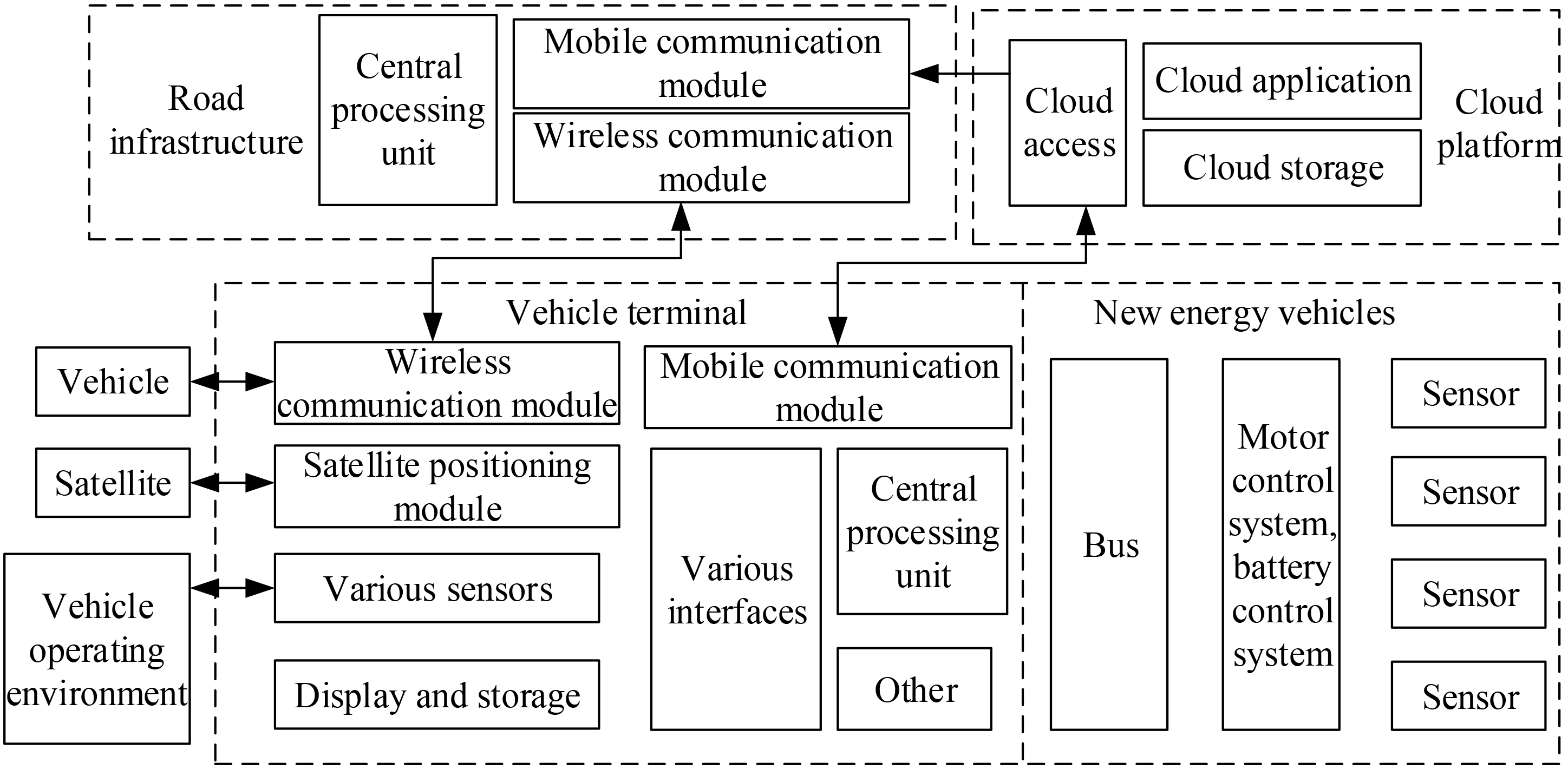
The electronic control technology of new energy vehicles is an on-board electronic control integrated system, which is mainly used for information collection, management and control, convenient operation and centralized display. The electronic control technology can also fully meet the requirements of on-board data access and management, processing and remote configuration of vehicle networking cloud service platform. It mainly controls the whole vehicle system, motor drive system and energy management system, so as to realize the functions of intelligent operation, dynamic configuration of power system, energy consumption management, remote data analysis and online configuration of new energy vehicles.
The core technology of Internet of vehicles is to develop a vehicle intelligent terminal with vehicle information sensing, Internet of vehicles and network identification, which will promote the transformation of its technology from road static to vehicle dynamic perspective. The breakthrough of Internet of vehicles technology in Internet of things technology, communication technology and cloud computing technology will promote the upgrading of the original automobile industry, communication industry and Internet industry. It is a systematic project, involving every layer of the system structure of the Internet of vehicles.
(1) Radio Frequency Identification (RFID): Through the radio frequency signal to identify the object, and collect the relevant information data, the automatic identification process does not need manual intervention. RFID can not only identify multiple objects in high – speed motion, but also facilitate data transmission between nodes, which has become the basis for the effective operation of the Internet of vehicles [8]. Active RFID provides long – distance reading and writing functions to realize remote communication and active sensing. It also has the characteristics of large amount of data storage, light and compact, waterproof and antimagnetic, long service life, high reliability and good security. RFID is incorporated into automotive electronic control and bus technology: ECU, CAN/K, etc. act on the system.
(2) Middleware technology: It is a kind of intermediate program that realizes data transmission, filtering and data format conversion between RFID hardware devices and application systems. According to different applications in the Internet of vehicles, various data information read by RFID reader is collected and extracted by middleware, decoded and filtered, and format converted, and then imported into the application program related to the Internet of vehicles, which is reflected by the application system to the user interface for users to use. Corresponding to various applications, RFID middleware and Internet of vehicles terminal software middleware should be developed, such as traffic signal control middleware, vehicle path navigation middleware, emergency response middleware, vehicle assistant driving middleware, etc. The development of various types of middleware must be implemented in accordance with the requirements of the Internet of Vehicles application service in accordance with relevant standards and protocols.
(3) Intelligent technology: The new intelligent network enables the system to perceive, acquire and remember the changes of external traffic conditions and environmental information for intelligent control. The intelligent system has learning ability and self – adaptive ability, and can use existing knowledge to identify, analyze, calculate, compare, merge, associate and judge information. It can make stress response to the change and stimulation of the outside world, convey the corresponding signal, and have the decision – making ability of behavior. Intelligent traffic navigation and unmanned driving are based on the application of intelligent technology.
(4) Cloud computing, cloud search technology: It is a tool for path planning suggestions, intelligent traffic dispatching remote analysis and diagnosis.
(5) Security: The openness, anonymity, tolerance, and complex application environment of the Internet of Vehicles will inevitably bring security risks. Therefore, the Internet of Vehicles must ensure the safe and accurate transmission of information and data, protect personal privacy, and prevent cyberattacks. Comprehensive and powerful capabilities to achieve the relevant requirements of confidentiality, integrity, authenticity, availability and controllability of information on the Internet of Vehicles.
(6) Reliability: The reliability design of the access layer, convergence layer and core layer of the Internet of vehicles is carried out. The IRF virtualization technology is used to improve the network reliability. The reliability networking model is integrated, and the solution is formulated and verified in practice to ensure the long – term normal operation of the system.
(7) Network protocol: Network protocol is a set of rules, standards or conventions established for the exchange of information and data in the network. The related protocols of Internet of vehicles can refer to the traditional mature TCP/IP protocol model and OSI (open Internet) network layering concept. Protocol stack refers to the sum of protocols in each layer of the network. OSI is integrated according to the rules of physical layer, data link layer, network layer, transport layer and application layer. The Internet of vehicles protocol defines the way to communicate with other systems. It describes the timing of signals and the structure of communication data.
(8) Sensor: Sensor and sensor information network are also the basis of information feedback of application management and control effect. Sensor technology affects on – board detection and diagnosis of OBD, and ensures the real – time, accurate and efficient operation and control of the system. The multimedia sensing technology of Internet of vehicles includes vehicle sensor network and road sensor network.
Construction of engine speed control model
In this paper, the average value model is used to analyze the overall external dynamic characteristics of the engine, ignoring the difference of the working state of each cylinder, and taking the average value of the cylinder variable difference caused by the different crankshaft angle in each working cycle. The average value model can maintain a certain accuracy and realize the nonlinear control of the engine. Considering the characteristics of the model, and according to the control of the engine speed in this paper, the engine is divided into three sub models in the modeling process, which are: throttle intake manifold sub model, combustion torque model, power output sub model. The principle of engine dynamic system is as Fig. 3.
Schematic diagram of engine power system.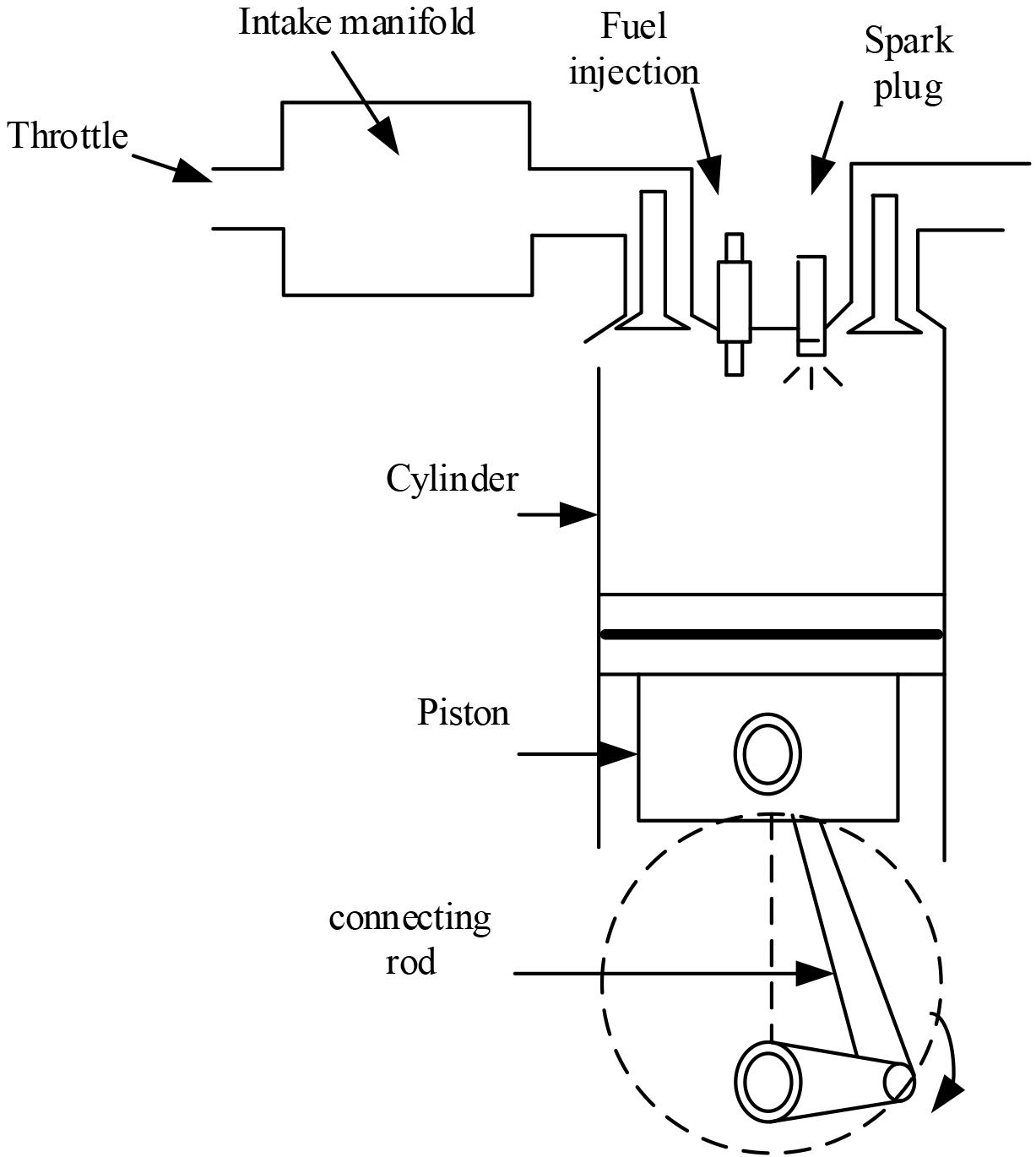
The air mass flow entering the cylinder is mainly determined by the crankshaft speed and the pressure in the intake manifold, while the air mass flow
Among them,
In Eq. (4.1),
In Eq. (3),
In Eq. (4),
In Eq. (5),
When the air enters the cylinder, the fuel injection quantity is determined by adjusting the air-fuel ratio. Under the action of ignition advance angle, the mixture in the cylinder burns to produce combustion torque. Therefore, the three main factors affecting the combustion torque are the air quality entering the cylinder, ignition advance angle and air-fuel ratio. When the engine is working, the fuel quantity must be in an appropriate ratio with the air mass sucked into the cylinder to form a combustion mixture. This ratio is called the air-fuel ratio [9]. The air quality of the cylinder can be obtained from the above model. If the air-fuel ratio is known, the amount of fuel to be injected can be uniquely determined.
The ideal air-fuel ratio is the minimum air mass consumed to fully burn each gram of fuel. If the air-fuel ratio is greater than the ideal air-fuel ratio, it is called lean mixture. At this time, there is more air and less fuel. Although the fuel can be completely burned, the fuel consumption is low and the pollution is reduced, the power is also low. The mixture whose air-fuel ratio is less than the ideal value is called rich mixture. At this time, the air is short of fuel for how long. Although the engine power is improved, the fuel can not be fully burned and the fuel consumption is high, causing great pollution [10]. In order to reduce fuel consumption and reduce pollutant emissions, the air-fuel ratio should be properly increased. For gasoline engines, the ideal air-fuel ratio is 14.7. Therefore, according to the above discussion, the optimal ignition angle
In Eq. (6),
In Eq. (7),
The torque acting on the engine crankshaft is mainly composed of combustion torque, pumping torque, friction torque and load torque. Newton’s second law can obtain the following equation:
In Eq. (4.3),
This article simplifies the model without losing the dynamic characteristics of the engine, ignoring some delays in the dynamic process, and finally sorts out the dynamic equation of the engine output speed as:
Speed selection of double working points
In the actual work of traditional automobile, the throttle position is determined by selecting the working mode. Because the average power demand of vehicle load does not match the power output from the optimal fuel consumption point under the special throttle position of the engine, and the total load in a single cycle is different, it is expected that the accumulator can realize charging and discharging once in each cycle [11]. Therefore, this article uses dual operating point speed control to ensure the energy saving effect of the fixed throttle system. The selection process of double working point speed is as Fig. 4.
Flow chart of double working point speed selection.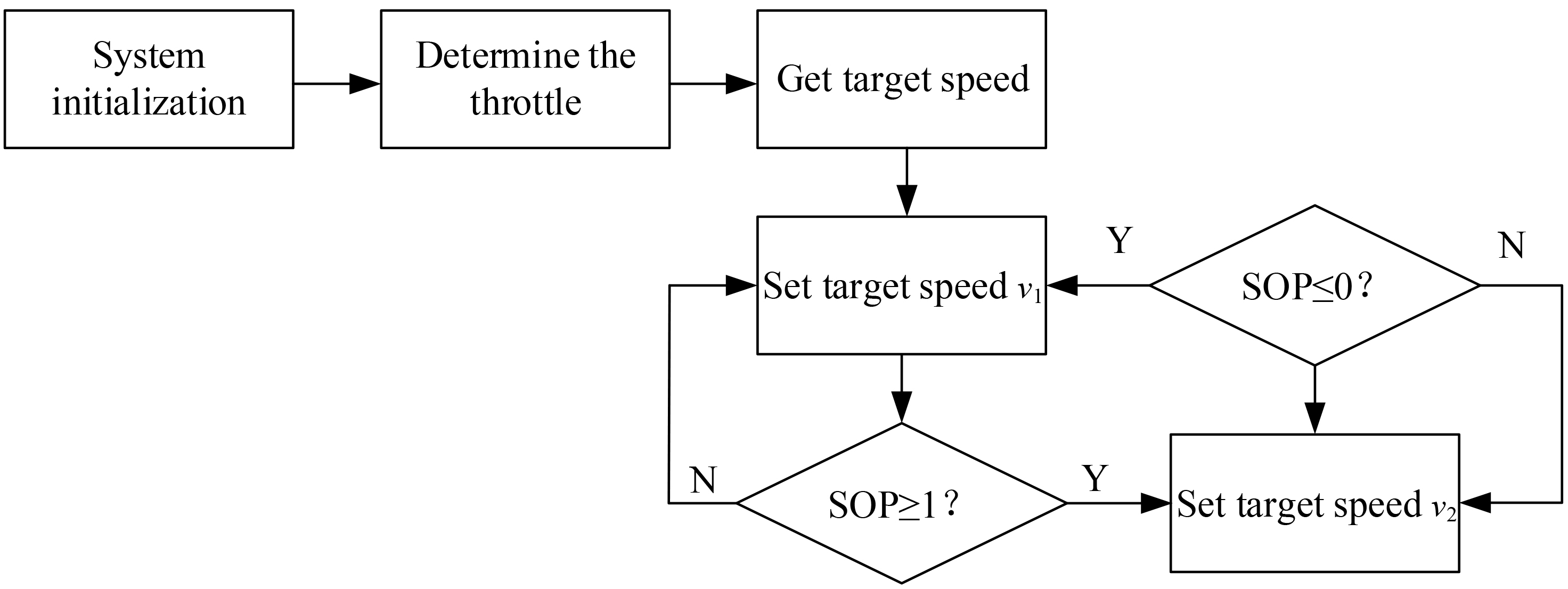
First of all, according to the working environment and content of the car, determine the appropriate working mode and throttle position. Select the optimal fuel consumption point and a secondary advantage at the throttle position to obtain the corresponding desired speed
Variable parameter PID closed loop control
After the speed is selected, maintaining the stability of the target speed is the guarantee that the engine is in the high-efficiency fuel consumption area. In the process of working, there are two kinds of fluctuation of engine speed with great difference.
(1) The load torque fluctuates near the torque corresponding to the fixed throttle working point, and the fluctuation range is small. The corresponding speed fluctuation is within the speed regulation curve range of the throttle working point, and the speed change is not obvious.
(2) The load torque exceeds the allowable torque value within the range of speed regulation curve for a short time and enters the range of full load speed curve. At this time, small torque change will bring about sharp change of speed [12].
In view of the above two different types of fluctuations, the variable parameter PID control of the engine is used to realize the stability of the speed. Through the dual operating point speed selection process, the target speed at the fixed operating throttle position is obtained, compared with the real-time speed of the engine, and the difference obtained is used as the input signal. The variable parameter PID controller is introduced, and the swash plate of the auxiliary hydraulic motor is calculated the tilt angle
In the Eq. (5.2.1),
On the basis of variable parameter PID control, this paper further introduces load prediction optimization speed control. The dynamic response coefficient of auxiliary hydraulic motor in the power transmission link is used to quickly compensate the torque change, so as to avoid the sudden change of engine speed and optimize the effect of variable parameter PID control. The actual required torque of the main pump is predicted by detecting the real-time outlet pressure of the main pump, the secondary pilot pressure and the pressure at the negative flow orifice of the system. Combining the swash plate inclination angle signal generated by the variable parameter PID control method to obtain the final auxiliary hydraulic motor swash plate inclination angle signal, the formula is:
In Eq. (11),
SOP (state of pressure) is defined as the ratio of the difference between the instantaneous pressure value of the accumulator and the minimum pressure value of the accumulator and the difference between the maximum pressure and the minimum pressure value of the accumulator [13], which is expressed by
In Eq. (12),
From the perspective of engine safety, when the difference between engine output torque and load torque demand is positive, the accumulator can absorb energy or not, but must release corresponding energy when the difference is negative [15]. From this, the mathematical expression required for the final inclination control of the auxiliary hydraulic motor swash plate is:
In Eq. (5.3),
Flow chart of engine speed control.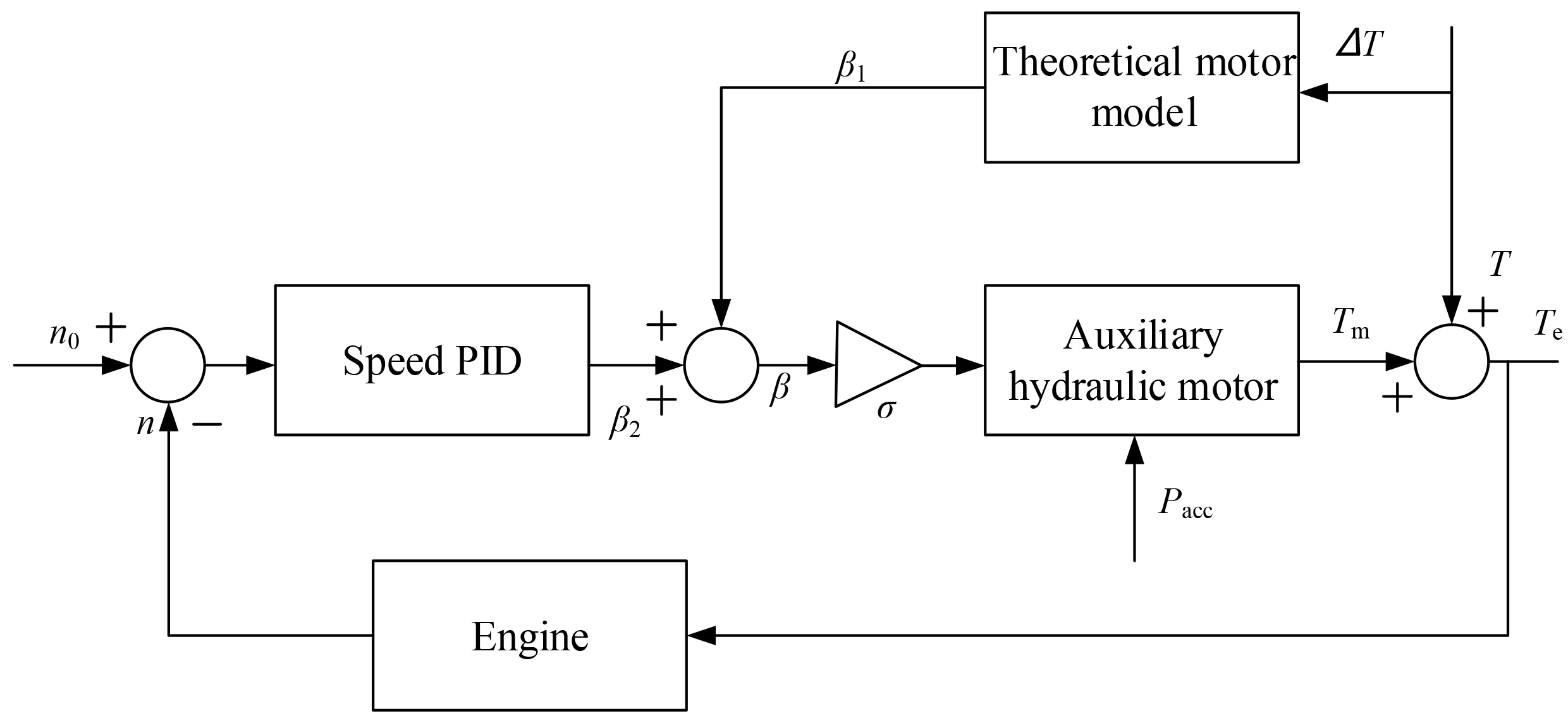
The control requirements reflected in the accumulator are: when the auxiliary hydraulic motor is required to absorb the excess energy of the engine, the accumulator can be filled with liquid until the maximum pressure of the accumulator is reached; when additional torque is required from the auxiliary hydraulic motor, if the speed difference is less than the speed regulating range set by the throttle position of the engine, the accumulator will stop discharging the fluid when the energy is released to the first and lower pressure. If the speed difference is greater than the speed range of the engine at the throttle position, the accumulator will release energy to the minimum lower limit pressure and stop discharging. According to the variable parameter PID control of the engine, the speed is stable. The load prediction is introduced to optimize the speed control. The SOP value is used to obtain the internal pressure value of the accumulator. Combined with the data of the pressure sensor on the vehicle, the energy storage capacity is judged and controlled to realize the engine speed control of new energy vehicles.
Set up the experimental environment
In order to verify the effectiveness of the new energy vehicle engine speed control method based on the Internet of vehicles technology, the experiment adopts a computer with Inter Core i5-3470 processor, 8.00 G memory, 800 G hard disk and 32-bit Windows7 operating system. Under the MATLAB environment, the engine simulation model is established, and the Fuzzy Logic toolbox is applied to automatically generate the fuzzy rule program. The parameters of the main components of the hybrid system are as Table 1.
Main component parameters of hybrid power system
Main component parameters of hybrid power system
Select 100 s in the experiment process as the analysis period, and compare the Reference [4] method, the Reference [5] method and the proposed method to analyze the actual engine speed of different methods. The experimental analysis results are as Fig. 6.
It can be seen from Fig. 6 that during the sampling period of 80 s, the Reference [4] method fluctuates in the range of 1500–1700 r/min, and most of the time is around 1580 r/min. The optimal fuel consumption point at this throttle position is around 1620 r/min, so the engine efficiency is low. The engine speed of the Reference [5] method is relatively stable, but the sudden change point of the speed is more severe, resulting in lower engine efficiency. This is because the torque provided by the auxiliary hydraulic motor in the hybrid power system is an additional load to the engine. It is caused by the lag response of the engine, and its peak value reaches 890 r/min–1680 r/min, which needs to be avoided in speed control. The engine speed of the proposed method is greatly optimized, and it can be stabilized near the two target speeds of 1500 r/min and 1620 r/min, and the peak value is 1490 r/min–1680 r/min. Only when the torque sudden change is large, the engine speed will fluctuate significantly, but the fluctuation value is small, and at the same time it can return to the stable area quickly, thereby improving the working efficiency of the engine.
Comparison of engine speed fluctuations of new energy vehicles
In order to verify the engine speed fluctuation of the new energy vehicle engine speed control method based on the Internet of vehicles technology, the Reference [4] method, the Reference [5] method and the proposed method are used to compare the engine speed fluctuation of different methods, as Fig. 7.
It can be seen from Fig. 7 that the engine speed fluctuation of the Reference [4] method is relatively large and the duration is long. The Reference [5] method requires large output torque, low static resistance torque of the engine, low damping of the torsional shock absorber, and obvious fluctuation of engine speed. The motor torque output of the proposed method has a faster response speed, can suppress engine speed fluctuations faster, its fluctuation range is only [
Comparison of energy-saving effects of new energy vehicle engines
In order to further verify the energy-saving effect of the engine speed control method for new energy vehicles based on the Internet of vehicles technology, the Reference [4] method, the Reference [5] method and the proposed method are used to compare the energy-saving effect of different methods. The results are as Table 2.
Comparison of energy-saving effects of different methods of engine work
Comparison of energy-saving effects of different methods of engine work
Comparison of engine working efficiency of different methods.
Comparison of engine speed fluctuations by different methods.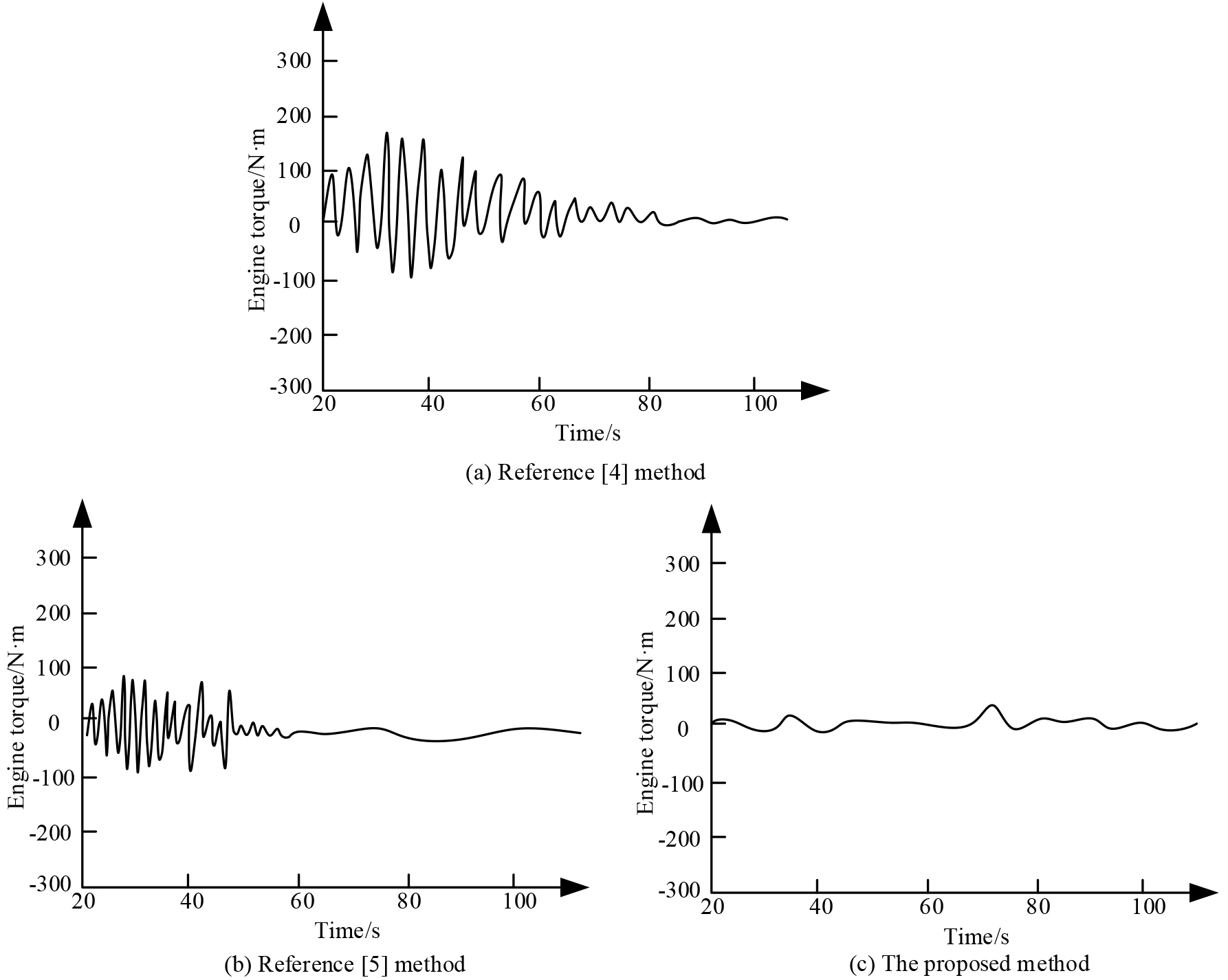
According to the data in Table 2, it can be seen that the Reference [4] method selects a larger throttle opening, but the fuel consumption is slightly lower. This is because in the hybrid power system, the engine works more in the high-efficiency fuel area, resulting in lower engine energy-saving effect. In the aspect of output power, the Reference [5] method has been greatly improved, but the energy-saving effect of the engine is not obvious. The proposed method integrates load prediction and variable parameter PID speed control, which can effectively improve the energy saving effect of the engine.
In order to improve the speed control effect of new energy vehicle engine, a new energy vehicle engine speed control method was proposed. The method was based on Internet automobile technology to achieve engine speed control. The experimental verification of the control method shows that the fluctuation range of engine speed is only [