
Abstract
In order to study the operating characteristics of variable speed constant frequency wind turbine under different working conditions and the monitoring system of wind turbine. In this paper, the simulation model of each component system of wind turbine is established by MATLAB/Simulink module, and the influence law of different wind speed and ground fault types on the output power of wind turbine is studied. The active power of wind turbines under different short-circuit fault types is compared. At the same time, in order to realize real-time monitoring of wind turbine speed and output power, an online monitoring system for wind turbine operation based on industrial Internet of Things is proposed, and the composition and operation characteristics of this remote monitoring system are given. The practical application shows that the on-line monitoring system can accurately and remotely monitor the running status of the wind turbine and avoid the unstable running of the wind turbine. The research conclusions of this paper can provide reference for the design and construction of wind turbines and the operation of connecting to the power grid.
Keywords
Introduction
As a clean, sustainable and eco-friendly energy, the superior performance of wind energy has been recognized by more and more scholars. In recent years, with the continuous development of wind power generation technology and the gradual increase of single machine capacity [3], its safety and reliability are becoming more and more obvious. With the continuous expansion of the construction scale of wind farm, the advantages of variable speed constant frequency wind turbine with large speed regulation range and low cost are reflected [6]. With the increase of the scale and proportion of wind power generation, the research on the compatibility, security and influence law of wind power generation on the stability of power grid needs to be improved.
In recent years, scholars at home and abroad have conducted in-depth and detailed research on variable speed constant frequency wind power generation [9]. With the continuous development of wind power generation technology, the problem of weak anti-interference ability of wind power has gradually become prominent. At present, there are many problems in wind power generation, such as the impact of grid bus voltage fluctuation on the stability of wind turbine, whether the grid is stable in the process of grid connection and the quality of power [7]. Based on this point, Waldner, M. and others proposed different control strategies for the stator and rotor of the wind turbine, so that the wind turbine can be stably connected to the grid [13]. Tentzerakis proposed the control strategy of prediction and correction of pitch, which can adjust the wind turbine speed in different wind speed environment and obtain appropriate wind energy capture [12]. Purvins, A. further optimized the control strategy and adopted the control strategy of hybrid energy storage system, so as to improve the utilization rate of system energy storage device [10]. Idan, M. considered the grid connection strategy under no-load and load conditions, and adopted stator flux control and rotor current control strategies respectively. An improved nonlinear function which can effectively improve the anti-interference ability of the system under different wind speeds was proposed [5]. Rui, X. and others built a nonlinear mathematical model of wind turbine. Then a nonlinear controller is designed to improve the power regulation ability [11]. The reference [15] proposed a hybrid power transmission system equipped with speed regulating differential mechanism, which can ensure constant frequency under different wind speeds, resonance and sudden load changes. At present, some results obtained by most researchers through research are obtained on the basis of some simplified models, mainly tackling the key control theory. However, the research on control strategy needs to be based on understanding the specific impact of various parameters on the wind turbine and system [14]. At present, there are few studies on the actual impact of wind turbine grid connection and external faults on power system stability, and most of them just stay in the model and simulation stage.
In order to study the influence of wind speed and fault on power system when wind power is connected to the grid. Firstly, this paper introduces the basic principle of each system component of wind turbine. The mathematical model is established according to the structural principle of wind turbine. Then, the simulation model of each component system of wind turbine and the model of wind power generation system are built by using MATLAB/Simulink module. The wind turbine model and power grid model are simulated. The impact of wind turbine grid connection on power grid under different wind speeds and the impact of wind turbine on power grid operation stability under different faults are studied.
Meanwhile,The actual wind turbine operation fault statistics show that the wind turbine bearing fault is the main cause of the ground fault after the wind power is incorporated into the power grid. Therefore, the wind turbine bearing fault condition monitoring is the basis of the wind turbine fault diagnosis. Its function is to complete the collection and transmission of the wind turbine bearing vibration signal through the sensor, and provide data support for the fault diagnosis research of the wind turbine bearing. In this paper, firstly, the overall system architecture of the wind turbine bearing fault detection device is analyzed and determined, and the wireless communication technology is analyzed and determined. Then, the communication protocol of the wind turbine bearing monitoring device is designed, and the hardware and software of the coordination node and the vibration monitoring node are designed.
Wind turbine foundation and mathematical model
Structure and operation principle of variable speed constant frequency wind turbine
Because the wind speed is random and uncertain, the amount of electric energy output by wind turbine generator will change with the change of real-time wind speed and direction. Therefore, it is of great significance to ensure the constant output power of wind turbines for the stability of the power grid connected by wind turbines [4]. The methods of keeping the frequency of variable speed constant frequency wind turbine generator unchanged are divided into: When the wind speed changes due to the change of wind speed, the purpose of constant frequency is achieved by controlling the frequency of excitation current and rotating magnetic field speed in the generator rotor winding; When the wind turbine is connected to the power grid, the rectifier device is connected for rectification, the switch circuit is controlled to invert the output, and the constant frequency sine wave with constant output and independent of the generator speed is obtained through filter filtering. The latter is more convenient and concise. This paper adopts the second method for variable speed constant frequency control [1]. Variable speed constant frequency wind turbine can be divided into several basic modules as shown in Fig. 1.

Basic structure diagram of variable speed constant frequency wind turbine.
The wind acts on the blades of the wind turbine to make the wind wheel rotate with the wind speed. The speed of the wind wheel increases through the gearbox of the transmission system to increase the speed to the rated speed of the generator, so as to drive the rotor of the generator to rotate, and achieve the purpose of converting mechanical energy into electric energy.
In order to simplify the wind speed model, the combined wind speed model is adopted in this paper. The combined wind speed model is the superposition of basic wind, gradual wind, gust wind and random noise wind [2]. The mathematical model of the combined wind speed model is shown in equation (2.1):
In equation (2.1),
Because this paper focuses on the energy conversion process of wind turbine blades in wind power generation system, the simplified aerodynamic model of wind turbine can be established by using wind energy utilization coefficient. The calculation equations of power and wind turbine blade torque of wind turbine energy conversion model is derived from the kinetic energy calculation equation of air flow in hydrodynamics. The output mechanical power of wind turbine generator is shown in equation (2.2):
In equation (2.2),
The variable speed constant frequency wind turbine used in this paper is not a direct drive type, but a transmission system composed of the wind wheel connected to the low-speed rotating shaft, variable-speed gearbox and high-speed rotating shaft through the rotating shaft, and then connected to the generator rotor [8]. Therefore, the transmission system model can adopt the typical three mass block model, considering the mass block of the wind turbine wheel, the mass block of the variable speed gearbox and the mass block of the generator respectively. The equivalent model of the transmission system of the wind turbine is shown in Fig. 2.
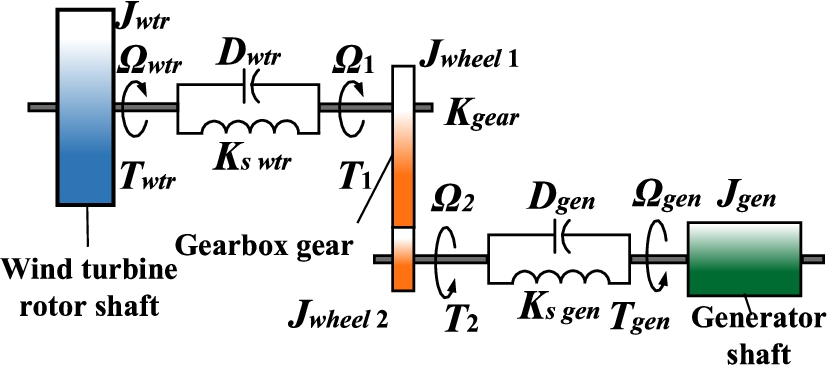
Schematic diagram of three-mass model of wind turbine drive system.
The advantage of one mass model is that by simplifying the number of equations and reducing it to only one system equation, the simulation speed of the model will be greatly accelerated in the system simulation calculation. In this paper, a mass block model is used to equivalent the interaction between the wind turbine and the generator to one end, so as to simplify the model of the transmission system and the model of the wind turbine transmission system. Therefore, the motion equation of the wind wheel is obtained, as shown in equation (2.3):
In equation (2.3),
In equation (2.4),
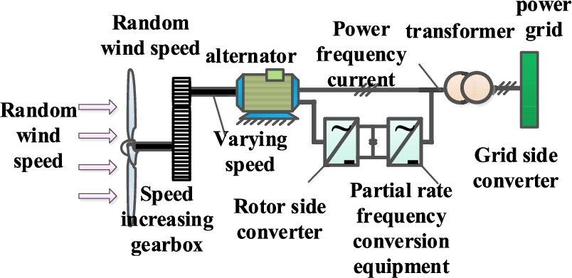
Overview of wind turbine grid connection technology
When the wind turbine is connected to the grid, in order to avoid excessive impulse current and impulse torque in the process of grid connection, the instantaneous value of the three-phase parameters at the output end shall be equal to the parameters of the grid at the grid connection, that is, the waveform, amplitude, phase, frequency and phase sequence shall be equal. The grid connection model structure is shown in Fig. 3.
The Simulink module in MATLAB is used to build the simulation model of each system component, and the built simulation model is simulated, as shown in Fig. 4.
The wind speed model sets the sampling time of random wind speed as 0.05 s, the gust is added at 4 s and lasts for 10 s, the maximum wind speed of gust is set as 6 m/s, the rated wind speed is set, that is, the average wind speed is 11.7 m/s, and the start time of step wind speed is 20 s. At the end of 25 s, the step wind remains for 3 s, the peak value of step wind is 6 m/s, and the simulation time is 50 s. According to the output wind speed waveform, the output real-time wind speed will fluctuate on the basis of the average wind speed according to the size of gust, step wind and random wind. When the input average wind speed is set at 11.7 m/s, the wind speed obtained by superimposing the four wind speeds is about 15 m/s to 20 m/s.
Grid-connected model of variable-speed constant-frequency wind turbine.

Transmission system simulation model.
Set the radius of wind turbine blade to 40 m. The air density in the atmosphere is 1.25 kg/m3. The cut in wind speed of wind turbine is 3 m/s. The cut-out wind speed is 25 m/s. The simulation time is 50 s. Set the modulation frequency to 50 Hz. Ten 1.5 MW wind turbines are combined into a 15 MW wind farm, which is connected to the 25 kV power grid through bus and transformer, and outputs power to the 120 kV power grid through 30 km transmission line.
According to the simulation model shown in Fig. 3 and Fig. 4, the output states of wind turbines under different operating states are analysed respectively.
When the average wind speed of the input wind speed is 5 m/s, the grid connection simulation results are shown in Fig. 5 and Fig. 6.
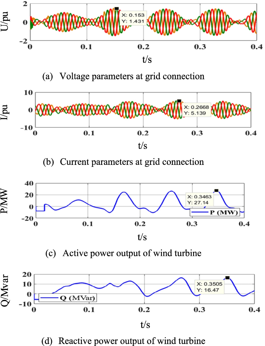
Grid connection results when the average wind speed is 5 m/s.
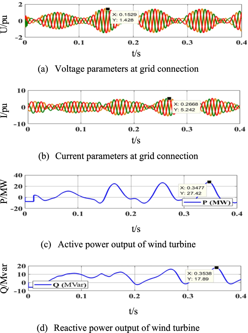
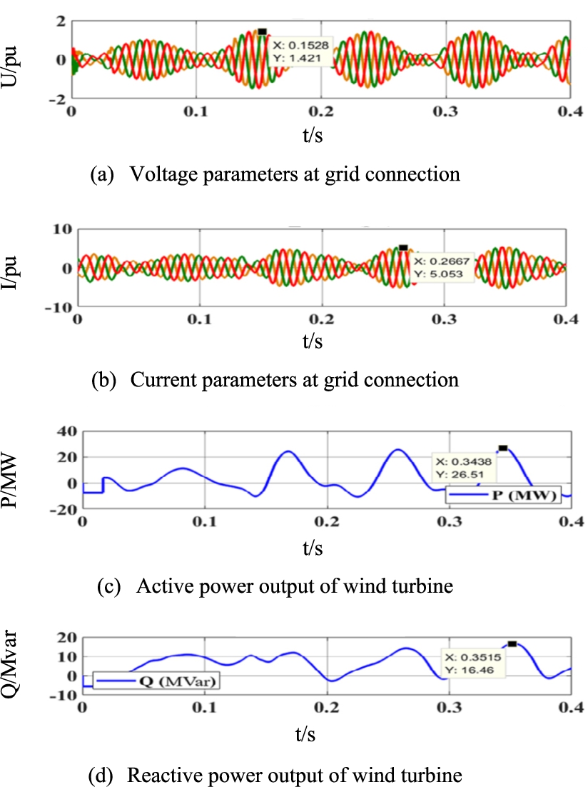
Grid connection results when the average wind speed is 11.7 m/s.
It can be seen from Fig. 5 that the maximum reactive power output of the wind turbine can reach 16.47 MVar and the maximum active power is 27.14 MW. In order to express the convenience, this paper uses the per unit value (per unit, p.u. or p.U., per unit value = named value/reference value) to express the change rule of the system voltage. The maximum voltage at the grid connection of wind turbine generator is 1.431 p.u. and the maximum current is 5.139 p.u., It can be seen from Fig. 6 that the maximum reactive power output of the wind turbine can reach 17.89 MVar and the maximum active power is 27.42 MW. The maximum value of voltage parameters at the grid connection of wind turbine generator is 1.428 pu and the maximum value of current is 5.242 p.u.
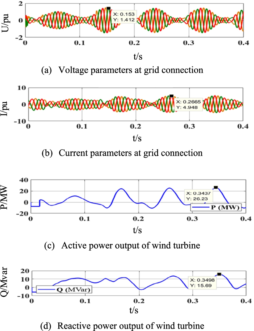
Grid connection results when the average wind speed is 20 m/s.
Grid connection results when the average wind speed is 25 m/s.
It can be seen from Fig. 7 that the maximum reactive power output of the wind turbine can reach 15.69 MVar and the maximum active power is 26.23 MW. The maximum voltage at the grid connection of wind turbine generator is 1.412 p.u. and the maximum current is 4.948 p.u.
Meanwhile, according to the above simulation data in Fig. 8, when the wind turbine operates at low wind speed and rated wind speed, the voltage and current values at the grid connection are almost the same. However, when operating at high wind speed and critical wind speed, the output voltage and current of wind turbine will decrease significantly. And because when the wind turbine operates at the rated wind speed, the current at the parallel node is the largest.
It is proved that the conversion efficiency of wind turbine to input wind energy is high at rated wind speed. In addition, when the wind turbine operates at high wind speed and low wind speed, the reactive power and active power output of the wind turbine are less than those output at the rated wind speed. And when the wind speed reaches more than 20 m/s, there is little difference between the active and reactive power output of the wind turbine and the output when the critical wind speed is reached. Because reactive power and active power play an important role in the stability of power grid voltage amplitude and power system frequency respectively. Therefore, when the wind turbine is connected to the grid near the rated wind speed, it is more conducive to the stability of the power grid system.
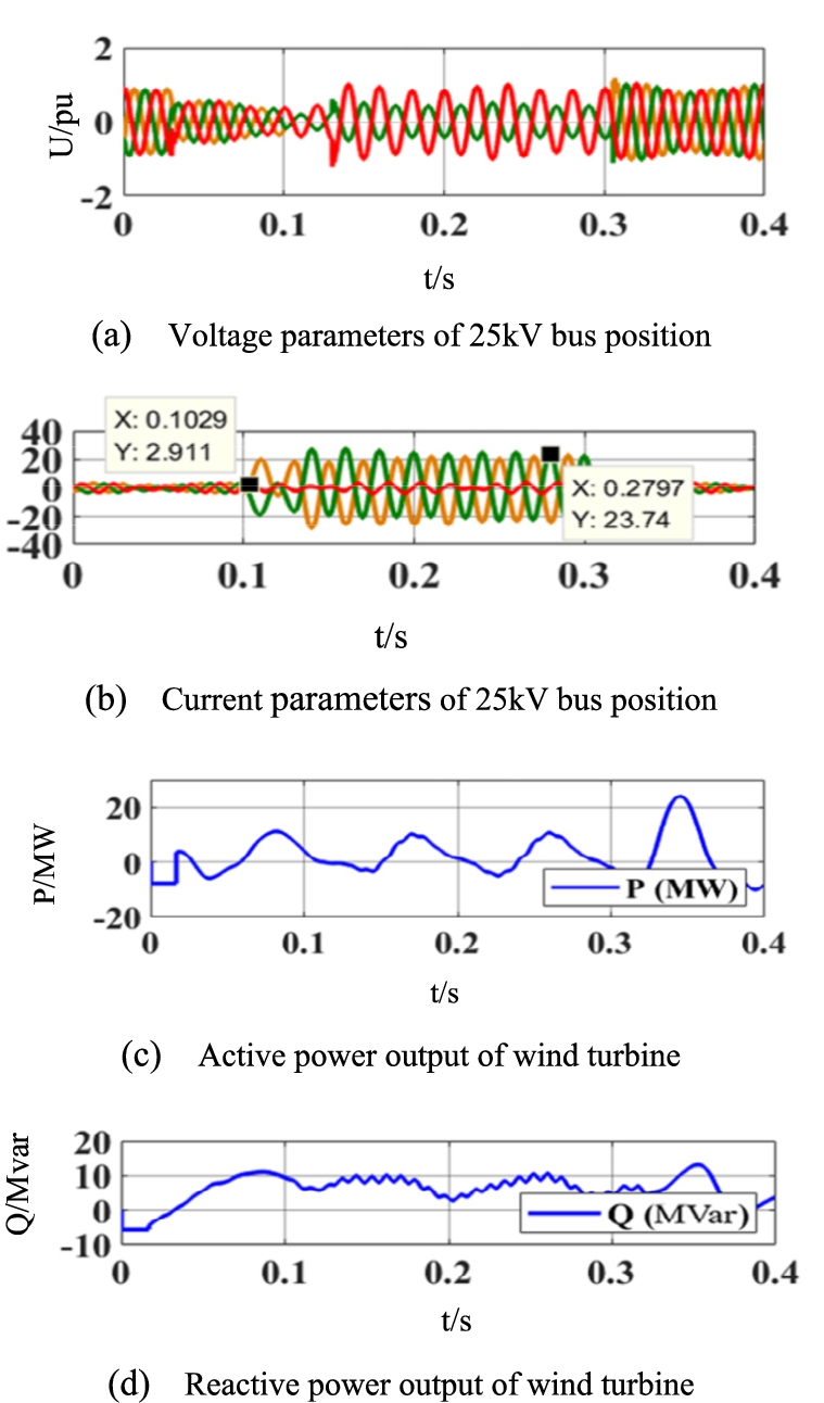
When the external system of wind turbine connected to the grid has short-circuit fault, the impact short-circuit current will bring great impact to the electrical equipment of the power system and seriously affect the stability of the operation of the power system. The simple faults in the actual operation of power grid include single-phase grounding short circuit, two-phase short circuit, three-phase short circuit and two-phase grounding short circuit. This paper discusses the impact of the grid connection of the wind power generation system on the stability of the power grid system when a simple fault occurs outside the wind power generation system. Therefore, the fault point is set at the 25 kV bus in the model. Assuming that a three-phase grounding fault occurs near the 25 kV bus and the fault starts at 0.1 s and lasts for 0.2 s, the simulation output results obtained by the power grid model are shown in Fig. 9.

Waveforms of various parameters after a three-phase short-circuit fault occurs.
Waveforms of various parameters after a two-phase short-circuit fault occurs.
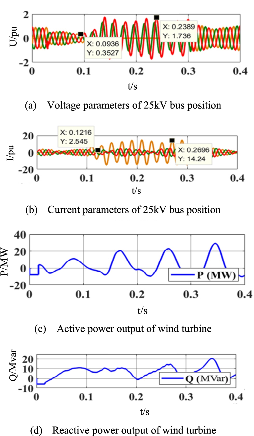
When a three-phase short-circuit fault occurs near the 25 kV bus, the voltage at the 25 kV bus decreases from 1.031 p.u. in normal operation to 0 p.u. The bus current increased rapidly from 2.768pu to 27.28 pu, producing about 10 times of impulse current. The huge impulse current will have a serious impact on the service life of insulation equipment. The disappearance of voltage will pose a serious threat to the stability of power grid system. It is assumed that the short circuit fault between A and B phases occurs near the 25 kV bus, and the fault starts at 0.1 s and lasts for 0.2 s. The simulation output results obtained by the grid model are shown in Fig. 10. Compared with the influence of three-phase short-circuit fault on the stability of power grid, the influence of two-phase short-circuit fault on the system is smaller. Similarly, the simulation results of two-phase grounding and single-phase grounding faults of wind turbines are shown in Fig. 11 and Fig. 12.

Waveforms of various parameters after a two-phase short-circuit to ground fault occurs.
Waveforms of various parameters after a single-phase short-circuit to ground fault.
Combined with the simulation results of Fig. 11 and Fig. 12, it can be seen that:When a three-phase grounding short-circuit fault occurs in the external grid line of the wind turbine, the bus voltage at the fault point will be reduced from 1.031 pu to 0, and about 10 times of impulse current will be generated, and the output active power will be reduced from 27.42 MW in normal operation to about 1.6 MW. The three-phase short-circuit fault has the greatest impact on the stability of power system, followed by two-phase grounding short-circuit fault, followed by two-phase phase short-circuit fault. The single-phase grounding short-circuit fault has the least impact on the stability of power system.
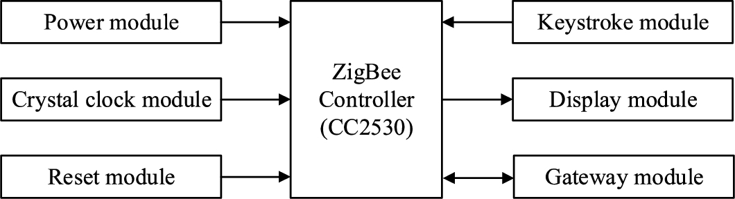
The bearing of the wind turbine is the key structure that affects the speed of the wind turbine, and the speed of the blade can be accurately monitored through the speed of the bearing, and then the operating state of the wind turbine can be monitored. In this paper, a fault monitoring system of wind turbine based on Internet of Things is designed. The system uses CC2530 as the main control chip. The Zig Bee terminal node is installed in the wind turbine to monitor the vibration parameters of the wind turbine bearing in real time. The vibration parameters collected by each node are summarized and packaged on the coordinator and sent to the web server through the gateway module. The vibration data of the wind turbine can be displayed and stored in the upper computer of the monitoring center. The upper computer can diagnose the fault according to the vibration data and display the running status of the wind turbine. The management personnel can conduct data query and management on the upper computer.
The overall architecture of fault monitoring system
Generally, the number of installed wind farms is more than dozens. The number of nodes that the wireless network can accommodate must be greater than the total number of installed wind farms. The monitoring network can cover all wind turbines and achieve comprehensive monitoring of the operating status of wind turbines. However, wireless sensor networks are usually powered by batteries, in order to reduce the number of battery replacements, the power consumption of wireless sensor networks must be considered. At present, several wireless communication technologies that are mature and widely used are wireless local area network (Wi Fi), Bluetooth, ultra-wideband communication (UWB), Zig Bee, etc. The comparison between several wireless communication technologies is shown in Table 1.
Comparison of several wireless communication technologies
Comparison of several wireless communication technologies
Zig Bee is a wireless communication method based on IEEE802.15.4 standard. Its working frequency band can be selected in 868 MHz, 915 MHz and 2.4 GHz. Under normal circumstances, the transmission distance can reach 100 m. After increasing the transmission power, it can reach 1–3 km. It can also use routing nodes as relay forwarding nodes between nodes to further improve the communication distance. Zig Bee technology has ultra-low power consumption, which provides feasibility for condition monitoring of wind turbines. The overall design scheme of the wind turbine bearing fault monitoring device is shown in Fig. 13.

Overall design scheme of monitoring device.
The monitoring device is mainly composed of Zig Bee node, gateway module, web server and monitoring center PC. The Zig Bee node is divided into terminal node and coordination node. The terminal node is responsible for collecting the vibration signal of the wind turbine bearing and sending the collected vibration signal to the coordination node. The role of the coordination node is to create and maintain the Zig Bee network. All terminal nodes send the monitored vibration data to the coordination node, and then the coordination node completes the subsequent operations such as packaging and forwarding. Because the geographical location of the wind farm is generally remote and there is no permanent staff on duty, the monitoring center cannot be set near the wind farm. Under normal circumstances, the monitoring center will have a certain distance from the wind farm, far beyond the transmission distance of Zig Bee wireless communication. Therefore, this paper uploads the vibration data collected by the Zig Bee node to the web server through the gateway after the coordination node is packaged and summarized, and then sends the data to the host computer of the monitoring center through the web server. The host computer displays the vibration data of the wind turbine bearing in real time and saves it to the database. In the host computer, the staff can view the real-time vibration signal of the wind turbine, and can also call the historical data for analysis and research.
The coordinator node is the core of a Zig Bee network. There is only one coordinator node in a network. Its role is to create a Zig Bee wireless network and to communicate with other network nodes. The vibration signals collected by all terminal nodes are sent to the coordination node directly or through the routing node, and then the data is uploaded to the web server through the wireless gateway. The overall structure of the coordination node is shown in Fig. 14.
Overall design block diagram of coordination node.
The coordinator node program is developed based on Z-Stack. After the coordinator node starts to run, it first initializes the program and creates a Zig Bee wireless communication network, and defines the network ID. After the network is created, the terminal node automatically applies to join the network. After the terminal node is successfully connected to the network, the coordinator enters the listening state and begins to listen to whether the vibration data collected by the terminal node is received. After the coordinator receives the vibration data sent by the terminal node, the data is packaged and sent to the gateway module. If the gateway module monitors the incoming data, it is necessary to first determine whether it is the data sent by the Zig Bee network. If it is, it indicates that the data is the vibration data collected by the Zig Bee node and needs to be uploaded to the cloud. If it is not from the Zig Bee network, it indicates that the data is illegal data for packet loss processing. Then repeat the above steps.
The vibration sensor node is the largest number of nodes in the Zig Bee network. It is mainly responsible for the collection of vibration signals of wind turbine bearings in the network. It has sleep mode and can reduce power consumption. Terminal nodes cannot communicate directly with each other, but they can communicate with routing nodes or coordination nodes. Vibration data can only be forwarded by routing nodes or directly sent to coordination nodes for further processing. The overall structure of the vibration monitoring node is shown in Fig. 15.
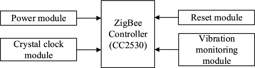
General design block diagram of terminal node.
The role of the terminal node is to collect the vibration data of the wind turbine bearing, and send the vibration data to the coordinator node by wireless communication or forward it to the coordinator node through the routing node. Like the coordinator node, the terminal node program design is also carried out on the basis of the Z-Stack protocol stack. After the terminal node starts to run, the program is initialized first, and then the terminal node will send the application for network access to the coordinator. After the coordinator agrees, the terminal node is successfully connected to the network. The Zig Bee protocol stack starts to run the relevant program into the listening state, and begins to listen to the timing sampling event defined by the program. In the timing sampling event, the vibration sensor sampling related program is executed, and A/D conversion is performed to convert the analog signal into a digital signal. After the conversion is completed, the vibration data is packaged and sent to the coordinator, and then enters the next certain period.
The vibration data of the wind turbine bearing monitored by the Zig Bee node are displayed on the host computer of the monitoring center after transmission, and the operation personnel view or export the data. The front-end sensors installed on the wind turbine, host computer, and backend management system are shown in Fig. 16. In this paper, the host computer and web server of the wind turbine fault monitoring system are designed, and the administrator login module, data monitoring module, data management module and database module are developed.
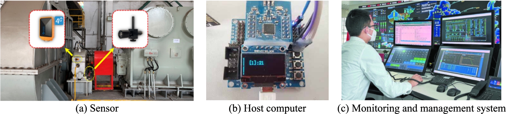
Wind turbine fault monitoring and management system.
Zig Bee nodes are divided into terminal nodes and coordination nodes. The function of terminal nodes is to collect vibration data of wind turbine bearings and send data to coordination nodes. The coordinator node is responsible for sending the data collected by the terminal node to the web server. In general, a Zig Bee network can only set up a coordination node, the number of terminal nodes depends on the number of wind turbines. Zig Bee node test steps are as follows.
A WIFI network should be created. The network name and password should be consistent with the name and password set in the gateway program. After the WIFI network is created, wait for the gateway module to join the network.
The coordination node is powered on, and the Zig Bee network is created after the coordination node is powered on. At the same time, the gateway module is used to automatically join the newly created WIFI network. After the successful access to the network, the next operation is carried out.
After the terminal node is powered on, it will automatically join the Zig Bee network created by the coordination node. After the network is successfully connected, the vibration sensor is driven to detect the vibration data, and then the data is sent to the coordination node.
After receiving the vibration data sent by the terminal node, the coordination node will display the vibration data on the display screen.
In order to realize the on-line monitoring of the running state of the wind turbine bearing and prevent the grounding fault of the wind turbine, this paper constructs the wind turbine bearing vibration monitoring network with Zig Bee technology as the core, and realizes the remote transmission and monitoring of the wind turbine bearing vibration signal by means of cloud communication combined with the host computer. The collected bearing vibration signal is sent to the host computer management system, and the management system analyzes the vibration signal to complete the fault diagnosis of the wind turbine bearing. In order to verify the performance of the fault monitoring device, the system test was carried out in a specific vibration environment. The test results show that the device meets the requirements of wind turbine bearing fault monitoring, and the preset functions such as vibration monitoring, remote transmission, host computer display, data management and fault diagnosis can be realized.
In this paper, various system components of wind turbine are built, including real-time wind speed simulation model, wind wheel simulation model, transmission system simulation model, generator simulation model and frequency modulation system simulation model. Through the model and simulation, the changes of power, voltage and current under different wind speeds and different faults are calculated.
The output power of the wind turbine and the voltage and current at the grid connection place have little difference when operating at low wind speed and rated wind speed, but when operating at high wind speed, the grid connection voltage and current output by the wind turbine will decrease. The three-phase short-circuit fault has the greatest impact on the stability of power system.
The running state of the blade can be monitored in real time by monitoring the speed of the bearing. a fault monitoring system of wind turbine based on Internet of Things is designed. The Zig Bee terminal node is installed in the wind turbine to monitor the vibration parameters of the wind turbine bearing in real time. The vibration data of the wind turbine can be displayed and stored in the upper computer of the monitoring center. The upper computer can diagnose the fault according to the vibration data and display the running status of the wind turbine. The management personnel can conduct data query and management on the upper computer. The system has good practical application value.
Footnotes
Acknowledgements
This work was supported by a grant from China Southern Power Grid Corporation Science and Technology Project (036000KK52190025-GDKJXM20198267).
Conflict of interest
None to report.