
Abstract
A hybrid renewable energy scheme comprising of the wind and solar PV electric power systems with appropriate maximum power point tracking is presented in this paper. The maximum power point tracking for the wind generator is carried out using Adaptive Neuro Fuzzy Inference System. The MPPT technique adopted for the photovoltaic power generation system is the Incremental Conductance (IC) algorithm. A power flow control scheme based on fuzzy logic is developed to regulate the power transaction from the wind and solar power sources as well as for the battery charging and discharging. Based on the available velocity of wind and solar insolation and based on the electrical demand different modes of operation are selected automatically using the ANFIS based control strategy. Considering the non linearity’s of the converters and the unpredictable nature of the renewable sources an advanced adaptive controller is necessary. The proposed ANFIS controller performs well and the proposed idea has been validated using MATLAB/Simulink and the simulation results are reported.
Introduction
The fast depleting fossil fuel and the world wide concern for global warming has triggered the research and development on renewable energy resources. A wide range of methodologies for harvesting renewable energy resources have been developed [1]. Wind, Solar Photovoltaic and Fuel cell based energy systems are the major renewable energy system. The photo voltaic power generation system has least requirement of maintenance and operational systems with least operational hazards [2] Solar power is highly environment dependent and it is not possible to derive the solar power during night. Partial shading and passing clouds are the challenges associated with the solar power generation. The positioning and orientation of the PV panel also plays an important role in power generation, and special arrangements like physical tracking in the direction of solar irradiation is required. The other disadvantage of the solar panels is that the power production process degrades with the rise in temperature. Also the photovoltaic panels require frequent cleaning from deposited dust. Wind energy systems are eco friendly but since the wind power conversion systems involve huge mechanical structures and dynamics the initial cost is high and the efficiency is also low [3]. The wind energy based power conversion systems also involve certain bottle necks. The wind velocity is not usually consistent over the year and is mostly seasonal. Even, during the wind season the density of wind, its velocity and the dominant directions usually unpredictably change. Since the wind energy power conversion system involves mechanical drives including gears and mechanical links the system needs frequent maintenance. Noise and frictional losses are some additional drawbacks with the wind power generation system.
However considering the conventional power generation systems the wind and the solar power have less run time expenses and require comparatively less maintenance and they are eco and environment friendly. Due to unforeseen nature of renewable energy sources, hybrid energy systems are used in order to meet the load with high quality and reliability. A standalone hybrid system incorporating wind, solar, storage battery, and diesel engine generator with advanced control on active-reactive power and dump power has been proposed in [4].
The operation and control of grid connected power electronic converters for Photovoltaic and Wind Power Systems is discussed in [5]. A novel control technique for improving the stability of Photovoltaic and Wind Turbine Grid-Connected Inverters for a Large Set of Grid Impedance Values is presented in [6]. The cuk and SEPIC converter incorporating hybrid DG system is proposed in [7]. Low cost hybrid energy systems are designed and implemented for household using rechargeable batteries with MPPT module in [8].
A residential roof top wind-PV with battery energy storage system of 4 kW rating is implemented in USA and its performance has been analyzed using available real data of wind speed and irradiance [9]. A semi isolated multi input DC-DC converter is proposed for hybrid wind-PV charging system [10]. An isolated hybrid system using a square-wave inverter to incorporate a PV with a wind-driven induction generator has been proposed in [11].
Hybrid diesel generator with MPPT control has been proposed in [12]. Lead acid battery design based on chemical kinetics for hybrid energy systems has been presented in [13].
Proportional Resonant (PR) controllers have also been implemented for grid integration of renewable energy sources and a proportional resonant controller and filters are developed for grid-connected voltage-source converters [14].
The Park transform based stationary frame controllers have also been developed for the better management of power integration into grid from renewable energy sources. Harmonic extraction algorithms and Delta operator digital filters for high performance in inverters have been presented in [15]. A detailed study of the Adaptive Resonant Controller for Grid-Connected Converters in Distributed Power Generation Systems had been demonstrated in [16]. The Sliding mode controller for the single-phase grid-connected photovoltaic system has been presented in [17].
In this work the demand of a standalone load is met with a combination of wind power and photovoltaic power system and a storage battery. The load side inverter is a three phase inverter and this is energized by the DC bus that is connected across the battery. The purpose of the battery system is to store energy when it is available in ample and to be used during the periods when neither the wind power nor the photovoltaic power generation is available. A Permanent Magnet Synchronous Generator is used for wind power generation. The wind and the photovoltaic power generation schemes require maximum power point tracking (MPPT). For the wind power generation we have adopted Adaptive Neuro Fuzzy Inference system of control and for the photovoltaic power generation system we have used the Incremental Conductance (IC) algorithm. In this work a novel hybrid energy harvesting system is presented. It consists of a wind power generator using the Permanent Magnet Synchronous Generator for the wind energy and a Solar Photo Voltaic system for harvesting the solar power. The overall power management is carried out by Adaptive Neuro Fuzzy Inference System. The ANFIS has been selected because the environmental conditions change in an unpredictable manner and that they change over a wide range. There is no single operating point where it can be linearised. So linear controllers face challenges in such an environment and hence the ANFIS method of control has been suggested. The proposed idea has been validated using MATLAB SIMULINK environment.
Proposed hybrid energy system
Figure 1 shows the block diagram representation of the proposed hybrid system. The hybrid system ensure the supply of uninterrupted power to a standalone three phase load and the load is supposed to be a sensitive load that cannot afford to power interruption.

Schematic diagram of Proposed Hybrid System.
The available energy sources are a wind energy conversion system and a solar power conversion system. The wind energy conversion system and the solar energy conversion system both are environment dependent. The wind power output at any instant is governed by the wind velocity and the solar power generation at any instant is governed by the solar irradiation and temperature.
These two power systems feed a common DC link through a chain of power converters to maintain an appropriate DC link voltage at the common DC link. A MOSFET based circuit is used to act as a switching device for charging and discharging the battery and it’s controlled by fuzzy logic controller.
The wind energy power conversion system comprises of a wind turbine and a Generator. In the wind power conversion system the kinetic energy carried by the wind is used by the mechanical turbine to translate the kinetic energy into mechanical rotational energy. To convert this into electrical energy electrical generators like PMSG, Induction Generator, Synchronous Generator of the DFIG may be used. In all these cases appropriate AC to AC or AC to DC or sometimes advanced power converts like the matrix converters have to be used. In this work, PMSG is used for electrical energy conversion. The torque output of the wind turbine is fed as the driving input for the PMSG. The PMSG and the turbine are coupled directly and therefore run at the same speed.
The output of the PMSG is a three phase AC output and its frequency will be as dictated by the speed at which the PMSG runs and this AC output is rectified by a three phase uncontrolled rectifier.
The AC output from the PMSG is converted into DC by uncontrolled half bridge three phase rectifiers. The output of three phase rectifier is boosted to be suitable for the DC bus bar feeding the three phase inverter. There are two dc-dc boost converters; the purpose of using the chain of two boost converters is to maintain the operating point in such a manner that the DC-DC boost conversion operation is stable.
With single stage DC-DC boost converter, a large gain value will be required, this large gain may push the system into unstable region of operation however with two stages of boost converter, they can both be operated with reduced voltage gain so that the cascade arrangement can produce the required DC link voltage at the same time the system is also stable.
In this work Adaptive Neuro Fuzzy Inference System is used for the MPPT of the wind energy conversion system. The output of this converter stage is the common DC link for the battery and the solar power conversion stage.
The solar system comprises of a bank of PV panels and the output of the solar farm is fed into a boost converter. Incremental Conductance (IC) algorithm is used for the MPPT of Photovoltaic panel based solar energy conversion system. The boost converter output reaches the common DC link and the DC bus bar is shared by the wind energy conversion system and the battery.
In both the renewable energy conversion systems DC to DC boost converters are used to uplift the voltage levels available to the required DC link voltage level.
There is a common Lead Acid battery bank connected across the DC link with the required ampere hour rating. The load side inverter is a three phase inverter and this is energized by the DC bus that is connected across the battery.
With a common load being served by a set of renewable energy sources and battery there could be the following modes of operation:
a. In mode 1, with sufficient availability of wind and solar irradiation both the energy conversion systems will be used. If the total available power is more than that is required for the load then the excess power available will be used to charge the battery and energy will be stored.
b. In mode 2, in the absence of the solar and wind power the battery is used to supply the required power to the load.
The following conditions and assumptions are maintained. The load needs uninterrupted power. The wind and the solar energy sources are individually sufficient to drive the load if available in full rated capacity. In the absence of the renewable energy sources the power handling capacity of the battery is sufficient to cater to the load. The ampere hour capacity of the battery is sufficient to individually drive the load for at least two hours.
With the operational requirements as marked as the two modes of operation and the constraints as given in assumptions the it is the responsibility of a n appropriate controller to handle the situations and to make appropriate decisions. The rules adopted in the FLC and the ANFIS ensure that these conditions are met with and the operational details are presented in the following sections.
Modeling of wind and solar PV system
As wind passes through the blades of the wind turbine a major part of the kinetic energy possessed by wind by virtue of its velocity is converted into mechanical rotational energy and the rest of the kinetic energy is passed along with the wind that passes past the wind turbine The velocity of the wind past the wind turbine is reduced that much.
The power produced by a typical wind turbine is given by
Where ρ is the wind density, Cp is the Power coefficient and V is the wind velocity and S is the area of impact on the wind turbine decided by the radius of the wind turbine blades. When the wind speed goes beyond the rated speed the pitch angle controller comes into action to reduce the wind turbine speed to be within the safe speeds.
The PMSG is a light weight alternator where the field excitation is provided by the permanent magnets. The permanent magnets are mounted on the rotor of the PMSG so that when the wind turbine revolves the permanent magnets spread a sinusoidal magnetic field. The stator is wound for three phase balanced system. As the turbine rotates, the magnetic flux produced by the magnets excite the stator windings to produce the three phase balanced sinusoidal emf.
The frequency of the AC output of the PMSG is given by the relationship
Where P is the number of poles and N is the speed of the rotor in RPM. The PMSG is modeled by the following equations:
Depending upon the wind velocity that varies from time to time the speed of the turbine has to be adjusted such that for the available wind velocity the PMSG delivers the maximum possible power output.
The mechanical power output of a rotating body is given by P = NT where N is the speed in RPM and T is torque in Newton Meter. The maximum power delivery happens, for any given wind velocity at an unique combination of N and T.
When exposed to sunlight, photons which have energy greater than the band gap energy of the semiconductor are absorbed and create some electron hole - pair proportional to the incident radiation in Fig. 2.

Equivalent Circuit of Solar PV System.
The equations of the output current is given by
Where
Then Equation (9) becomes
The I-V characteristics of a solar PV cell is given by
Ipv is the current generated by the incident of light, I0 is the diode reverse bias saturation current. Rs starting resistance, Isc is the short circuit current, q is the electron charge; K = 1.38× 10⁻²³ is the Boltzmann constant; T is the temperature of the p-n junction and A = 2 is the diode ideality factor.
Depending upon the nature of the renewable energy, its magnitude and basic physical and dynamic properties, and also depending upon the bus bar where the various sources are to be integrated the appropriate power converter is to be chosen. Irrespective of the power converters used an MPPT is required in all converters that are used along with renewable energy sources that offer unpredictably swinging power outputs.
Adaptive neuro fuzzy inference system for MPPT in wind energy system
If the energy harvested through the wind turbine changes, because of the changes in the wind velocity and since turbine and the motor shaft structure is a fixed load the parameter that will get adjusted is the speed of the turbine. The speed of the turbine has to be adjusted appropriately such that the power harvested is maximum for that particular available wind velocity. The characteristics of a typical wind turbine is shown in Fig. 3.
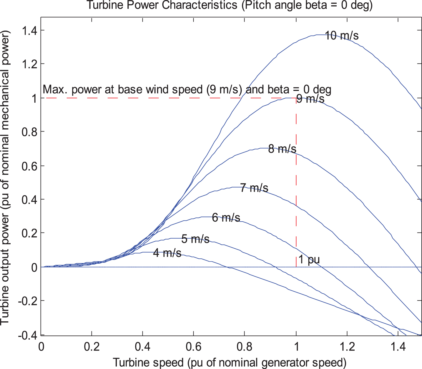
Characteristics of a typical wind turbine.
When the wind velocity is 9 m/s the turbine runs at the rated speed of 1 PU delivering 1 PU Torque. The power output therefore is 1 PU. At all other speeds less than 9 m/s, for every wind velocity the turbine has to be run at the appropriate speed such that the torque is maximum and thus the power harvested is also maximum. If the turbine is run at any speed on either side of the peak torque value the torque produced is reduced. Therefore as and when the wind velocity changes the turbine speed is to be adjusted by an automatic system that guarantees maximum power harvest and this is called the MPPT. In all our considerations, as long as the wind velocity is less that the rated value the pitch angle is not manipulated. When Fig. 4 shows ANFIS based MPPT for Wind Energy system.

ANFIS based MPPT for Wind Energy system.
In the traditional fuzzy logic controller the experience of the operator or the designer is incorporated into a set of rules and based on this rule base decisions are made. For that purpose, the error and error rate associated with the parameter to be regulated are viewed in a fuzzy scale, the entire range of which is called the universe of discourse, divided into a number of segments. Over each of the segments are drawn the membership functions and the membership functions can be of any shape typically triangular, trapezoidal, Gaussian etc. The fuzzy logic controller in the basic form has some limitations such as large time consumption in making decisions, a bit difficult to implement in hardware and there is a compromise between agreeability and accuracy. To overcome this ANFIS is used. The wind generator speed and actual speed are the input data to the ANFIS and the output of the ANFIS controller is the duty cycle for the boost converter switch in order to track appropriately the MPP.
In the case of ANFIS the range of each of the segments and the rules by which the fuzzified values of error, error rate and output can be related are decided by the ANFIS itself and not by the designer.
The ANFIS based MPPT controller computes the optimum speed for maximum power point using information on the magnitude and direction of change in output power due to change in speed. The ANFIS controller is used to search the optimal rotational speed which tracks the maximum power point at variable wind speeds. Figure 5 shows the Structure of ANFIS.
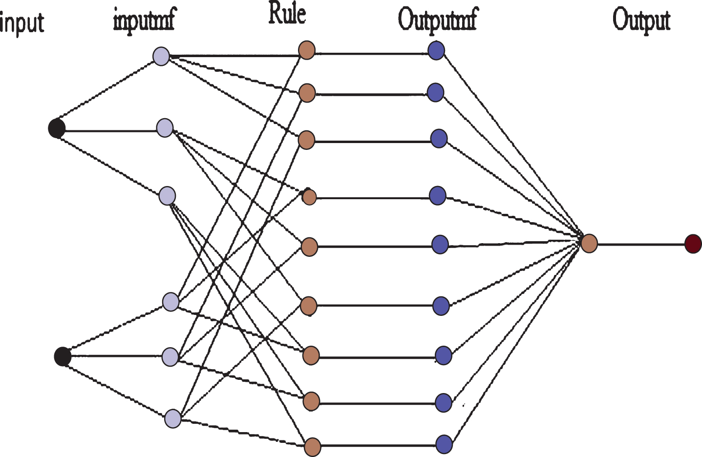
Structure of ANFIS.
In this application the Sugeno type of FLC is used and the numbers of membership functions were three. The numbers of rules formed by the ANFIS were 9. The ANFIS was trained for 3000 iterations.
Maximum Power Point Tracking (MPPT) is a technique to harvest the maximum power available across the terminals of the PV panel that varies from time to time dependent upon the solar irradiation and temperature. Unlike the conventional power sources the driving capability of the solar panels is not a constant and as such the load has to be altered according to the changes that occur in the PV panels with regard to power generation capability.
With the MPPT scheme the effective load side resistance of the converter and load combined is made equal to the effective source resistance of the solar panel. The source resistance of the solar panel is a function of solar irradiation and the temperature that are unpredictable environmental factors and therefore we need an automatic MPPT system. Usually, it is the DC to DC converter or the DC to AC inverter that receives power from the PV section. These power electronic systems operate with pulse width modulation technique. The duty cycle or the modulation index of the power electronic converter used is the manipulated parameter to ensure MPPT.
Incremental conductance algorithm for MPPT in solar photovoltaic system
The Perturb and Observe and the Incremental conductance methods are the most popular of the MPPT techniques. The Perturb and Observe method suffers from the drawback of oscillations about the maximum power point. The incremental conductance method overcomes this drawback and gives a more stable operation while properly tracking the maximum power point as well [20].
Consider the Voltage current characteristics shown in Fig. 7. With respect to the V (Vs) I characteristic curve there are two points of interest one on the X axis or the voltage axis and the other on the Y axis or the current axis. On the voltage axis at the extreme point where the curve meets the axis is the point when the PV panel is left open circuited and the PV voltage is maximum for the given solar insolation. Similarly on the Y axis is an extreme point where the curve meets the Y axis and this point corresponds to the short circuit current that flows through the PV panel when its terminals are short circuited.
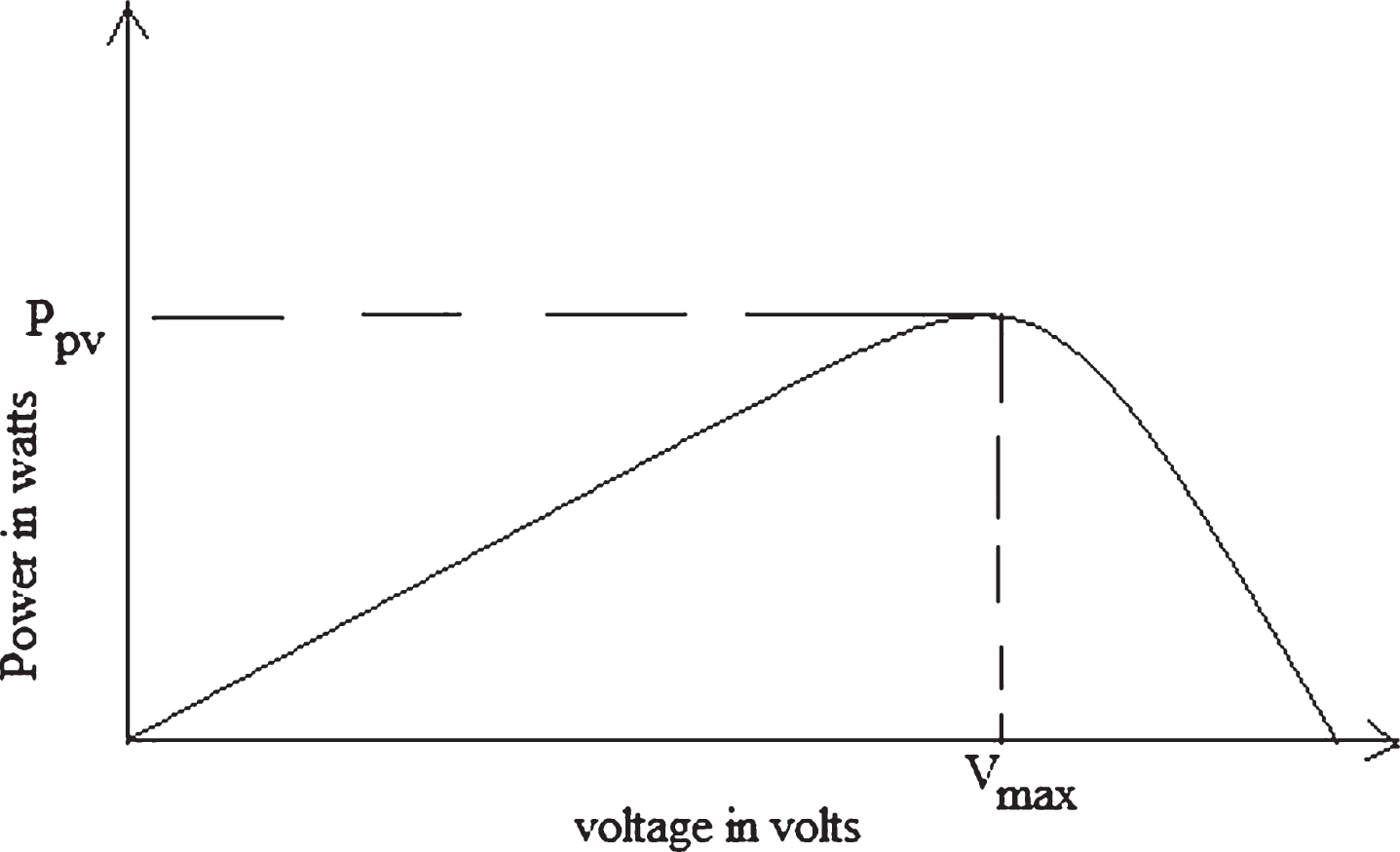
Illustration of MPPT in solar PV system.
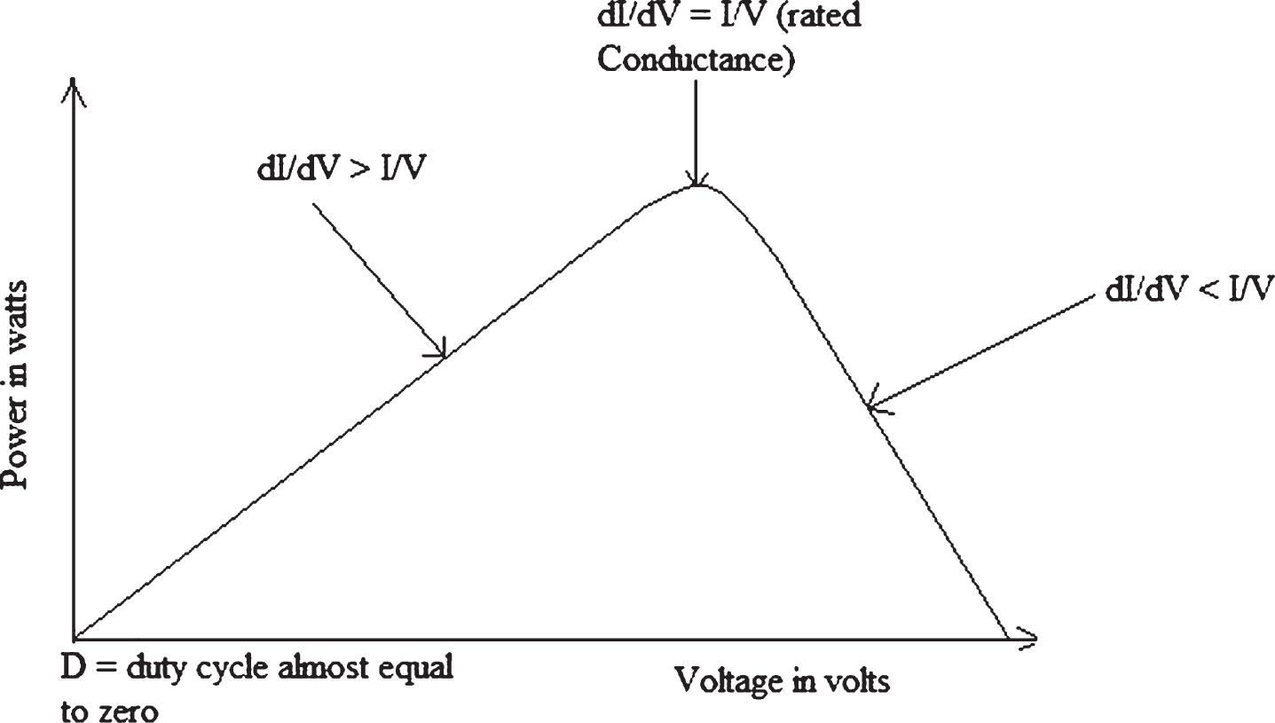
Voltage vs Power Characteristics of IC algorithm.
On both these two extremes the power delivered to the load by the PV panel becomes zero as any one of the two parameters V or I becomes zero at these two extremes. The electrical conductance of the system of PV panel is the ratio between I and V and at any point along the Y axis the conductance is infinity while it is zero along the X axis.
For any given solar insolation there is a corresponding V I curve and there exists a point on the curve, at the knee of the curve, when its direction abruptly changes. In the segment of the V I curve between this knee point and the point where the curve meets the Y axis the conductance is high as I is fairly high compared to V. As we move along the segment from the knee point towards the Y axis, V tends to become zero and I tends to become maximum. The rate of change of conductance is also very small. There are many MPPT techniques that are used for the implementation with Photo voltaic power generation systems. The Perturb and Observe, also sometimes referred to as the hill climbing technique, and the Incremental Conductance technique are the two popular techniques of MPPT [18–20]. However soft computing based techniques like the Fuzzy Logic Controller, the Artificial Neural Network Based controller and the ANFIS based MPPT control schemes are also available now days. However in this work the Incremental Conductance is adopted for MPPT.
Space vector modulation (SVPWM) is a technique used in the three phase inverter that gives a balanced three phase AC voltage output with improved power quality as compared to the sinusoidal PWM. In the topology of the three phase three leg inverter there are six switches arranged in three legs. Each leg is called the node and thus the AC voltage output is drawn across the three nodes of the three phase bridge.
The switching states of the inverter switches are represented as a three element vector [a b c]. where [a b c] = [1 1 1] indicates that all the upper switches are on and [0 0 0] indicates that all the lower switches are on. In a three phase inverter of the 180° degree conduction mode, of the six switches, at any instant at least three switches are to be in the On state. If all the upper switches or all the lower switches are turned On, then the voltage across the three phase inverter output will be zero and hence these two states are called the Null state. The other six possible states viz. [1 0 0], [1 1 0], [0 10], [0 1 1], [0 0 1], [1 0 1] are known as the active states. The locus of the space vector is a circle and there are six sectors of 60 degrees over this circle. A hexagon can be completed inside this circle with the vertices of the hexagon lying in the circle with a displacement of 60 degrees. The six active switching states correspond to the six vertices of the hexagon as shown in Fig. 8.
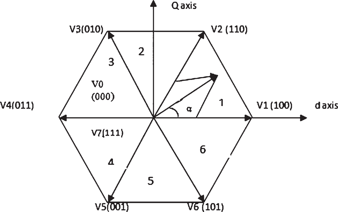
Hexagon diagram for SVPWM.
Even as the reference space vector moves along the circle in a continuous manner it is assumed to be in uniformly distributed discrete positions over the circle for each cycle of AC voltage produced. The number of revolutions in each second is equal to the frequency of the AC voltage output. During the stay of the space vector in each of the uniformly distributed positions, depending upon the angular position of the space vector and the modulation index four states of the switching vector are used alternately for calculated periods called as dwell times [21]. For example as the space vector passes through the first sector the switching vectors [0 0 0], [1 0 0] [1 1 0] [1 1 1] are sequentially activated for prescribed periods and then the same switching vectors are used in the reverse order [1 1 1], [1 1 0], [1 0 0] [0 0 0].
The three phase line voltages produced are Vab, Vbc and Vca and these three line voltages are related to the switching vectors as given by the following equations.
With the switching vector [1 1 1] the line voltages will be V ab = V bc = V ca = 0 and with the switching vector [1 1 0] the line voltages will be V ab = V dc (1 – 1+0) = 0; V bc = V dc (0+1 – 0) = 1; and V ca = V dc *(– 1+0+0) = – 1;
The three phase voltages V
a
, V
b
and V
c
are related to the switching states as given by the equation given below:
With the switching vector [1 1 1] the phase voltages will be V ab = V bc = V ca = 0 and with the switching vector [1 1 0] the phase voltages will be
V an =(V dc /3)(2 – 1+0) = V dc /3;
V bn =(V dc /3)(– 1+2 – 0) = V dc /3; and
V cn =(V dc /3)(– 1 – 1+0) = – 2V dc /3.
The various line voltage and phase voltages pertaining to the balanced three phase voltage system are generated as per the 8 possible switching vectors.
In this work the space vector modulation with closed loop control using a PI control scheme is used for the regulation of the required voltage across the three phase load.
In this work, the power flow control is carried out using Fuzzy Logic Controller (FLC). All input parameters viz. the available wind power, the available photo voltaic power, the state of charge (SOC) of the battery and demand on the load side are all continuous quantities. The complete range of the available wind power can be segmentised as low, medium and high levels. Similarly the photo voltaic power, the SOC of the battery and the load are segmentised as low, medium and high values are shown in Table 1.
Fuzzy Rule Base for the Proposed System
Fuzzy Rule Base for the Proposed System
A rule base is created based on the experience of the operator. The following is a set of examples of rules. Rule: If both wind power and the PV power are high and if the demand is low and if the SOC of battery is low then the battery should be charged. The quantities like wind power (W), solar power (S), load demand (L) and SOC of battery (B) are measured and related by the rule matrix to make the important operational decisions. Some of the key rules are presented herein. The quantities like W, S, L and B are measured and related by the rule matrix to make the important operational decisions. The universe of discourse of all the variables are segmentised and fuzzified. Each of the variables is divided into three segments and the triangular membership functions are used for all the variables. A maximum of 81 different rules can be formed. While W, S, L and B are the measured system parameters the two degrees of freedom available for power flow control are the PWM control of boost converter B2 and the battery charging switch S. Some of the key rules are presented herein. The duty cycles of these controllers are decided by the fuzzy rules.
Figure 9 shows the same input ranges and the given parameters of wind, solar, load demand and SOC and the same output ranges of PWM and Charge control respectively.
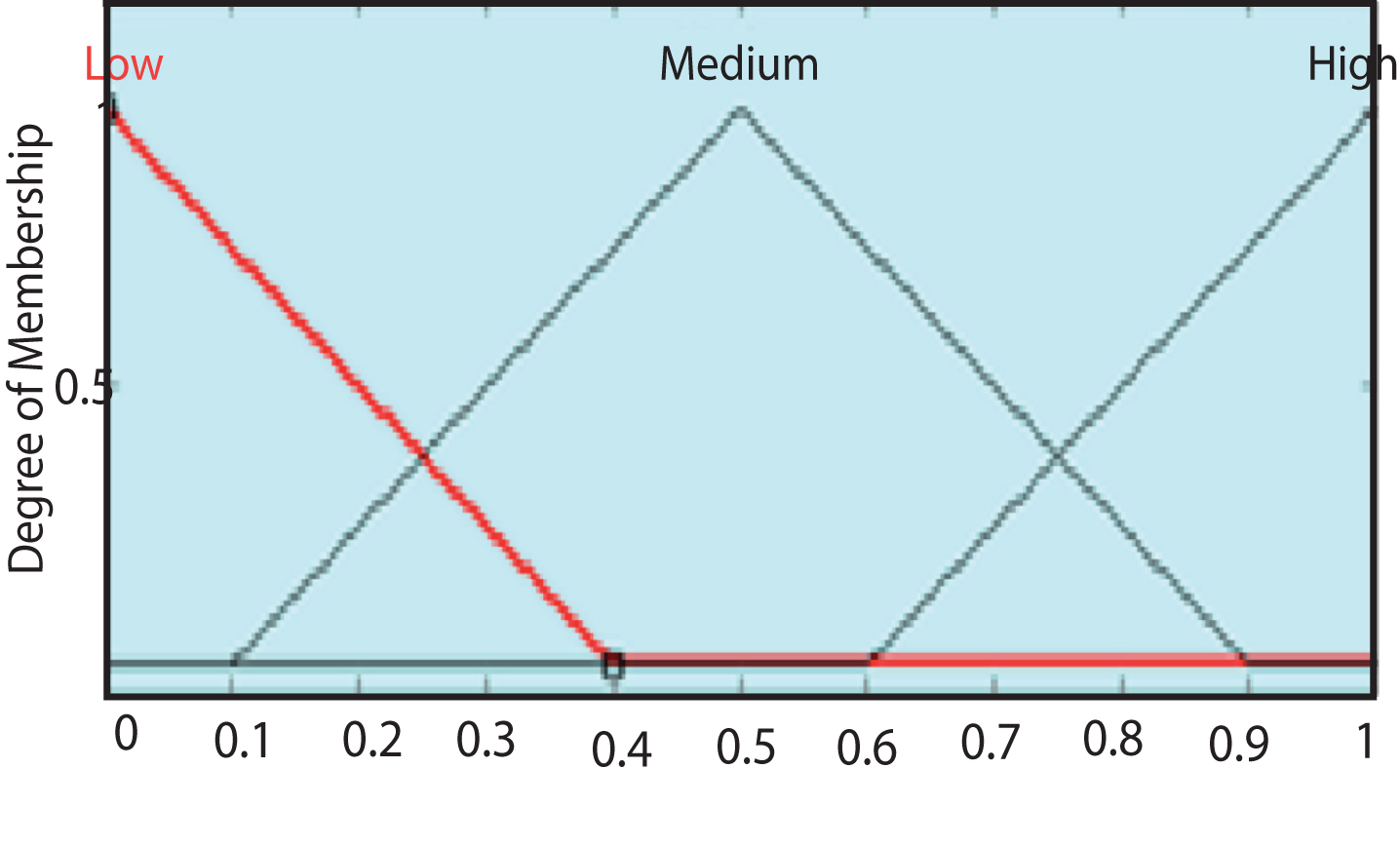
Membership functions of the input and output variables.
The work focuses on a standalone system in which the wind and the solar power are harvested whenever available and routed to an inverter section. The excess energy available is stored in the battery. The power rating of the PMSG, the Solar Panel and the power electronic converters have been selected so as to meet the possible power transactions given in Table 2.
Hybrid System Parameters
Hybrid System Parameters
This section discusses the simulation carried out on the hybrid energy system. The ratings of the sources and the load are given in Table 2. The demand to be met by the hybrid power system is 12 KW. This demand has to be met with the wind energy source of 15 KW and the additional solar Power capacity of 2 KW. Although the wind source is apparently over sized, since the wind velocity is of highly variable in nature it is expected that only at peak wind seasons the power output would reach 15 KW level. A storage provision is made in the form of lead acid batteries of rating 5000 AH at a terminal voltage of 500 V to be used when the power generation is more than the demand. During off wind periods of the day, the batteries will be used as supplementary power to supply the loads.
The complete simulation of the proposed system in the MATLAB/SIMULINK environment and the performance of the proposed system has been evaluated. The Simulink model of the complete system is shown in Fig. 10.
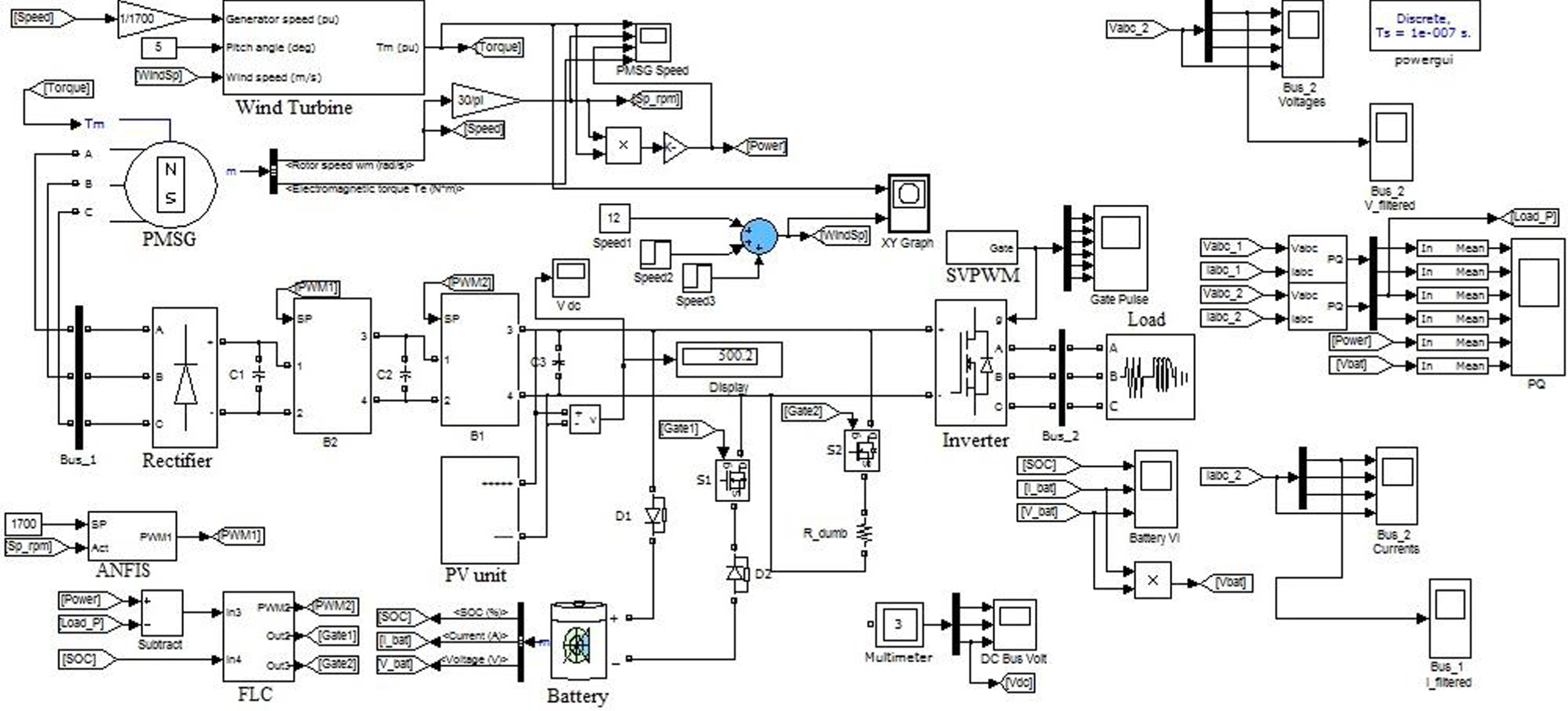
MATLAB/Simulink diagram of Hybrid System.
The wind turbine PMSG sub system the photovoltaic sub system the chain of power electronic converters and the load are the main sub systems. The wind turbine and PMSG sub systems convert the wind energy into electrical energy. The torque output of the wind turbine is fed as the driving input for the PMSG. The PMSG and the turbine are coupled directly and therefore run at the same speed. The output of the PMSG is three phase AC output with variable frequency and it is rectified by a full bridge rectifier. The wind turbine considered for this study is a 15 KW turbine with a nominal speed of 9 m/s.
The DC to DC converter B2 draws power from the output of the rectifier that converts the AC output of the three Phase output into DC. The converter B2 is a DC to DC boost converter. The DC to DC boost converter is of the simple generic converter with a boost inductor and a capacitor filter at the DC output. The diodes are used for reverse blocking. The switching pulse for this converter is generated by the PWM sub system that uses a carrier of 20 KHz. The reference is derived from the ANFIS controller that decides the duty cycle in accordance with the ANFIS based MPPT for the wind turbine.
The MPPT for the wind power generation is implemented using an ANFIS controller. The inputs to the ANFIS controller are the set speed and the actual speed of the generator. The set speed is given by a Table 3 that gives the required speed to be used by the generator in accordance with the wind speed supplied by a wind speed measuring anemometer.
Wind speed data Sheet
Wind speed data Sheet
Figure 11 (a) shows before the implementation of the ANFIS based MPPT. For this purpose based on the characteristics of the Wind turbine an FLC based MPPT was first designed The performance of the FLC was assessed and upon observing the satisfactory performance of the FLC the data pertaining to error and error rate were collected at the work space of the MATLAB.

(a) Training data Vs Output in ANFIS. (b) Time vs Power in KW. (c) Epochs vs Error in ANFIS.
The FLC based MPPT for the wind power harvesting was carried out. The FLC tracked the maximum power with respect to changes in the wind velocities happening now. However with the ANFIS this draw back was over one and the system with the ANFIS based MPPT could harvest 14.9 KW as much close to the predicated value as possible.
After collecting this data the error, change in error and the corresponding error were used by the ANFIS to get trained and the training was carried out for 3000 epochs or until the error becomes zero. The actual training used 3000 iterations and error was reduced to about 0.0012, as shown in Fig. 11(b) which could be considered as zero for practical purpose.
The DC to DC boost converter B2 is used to boost the output voltage often DC to DC boost converter B1. This converter is used to maintain the DC link voltage and also it gives an additional degree of freedom and its duty cycle is controlled by the FLC. The structure of the DC to DC converter B2 is of the same structure as the B1 converter.
Figure 12 shows the wind profile considered for simulation up to t = 0.5 s the wind velocity is 7 m/s and afterwards the velocity is 9 m/s. Under such condition the solar panel supplements additional power to a maximum of 2 KW while the remaining demand is met by the battery.

Time vs Wind speed profile.
Figure 13(a, b) shows the wind turbine runs the PMSG and the PMSG delivers a three phase voltage output at a frequency as decided by the speed of the PMSG machine. The next stage is a three phase rectifier system and the output of the rectifier is filtered and is fed into a boost converter. With a wind velocity of 9 m/s and 7 m/s the generated power is 15 kW and 7.5 kW is shown in Fig. 13(a,b) the DC voltage at the rectifier stage is just 130 V.

(a) MPPT of Wind Energy System. (b) MPPT of Wind Energy System.
Figure 14(a, b) shows that the power generation of the Wind power generation was respectively 7.5 kW and 15 kW at a Wind speed of 7 m/s and 9 m/s.

(a) Time vs Wind power for 7 m/s. (b) Time vs Wind power for 9 m/s.
The photovoltaic power system comprises of the Solar panel arrays and the boost converter with the IC algorithm based MPPT control. The open circuit voltage of each panel is 22.2 V and since 48 panels are cascaded the total open circuit voltage becomes 22.2×48 and since the V pmax of each panel is 17. 2 volts the total V pmax will be 17.2×48.
The total V oc = 22.2×48 = 1065.6 V
The total V pmax = 17.2×48 = 825.6 V
The DC voltage required is 600 V DC and the required duty cycle should be 600/825.6 = 0.7267.
The Incremental Conductance (IC) algorithm ensures that the maximum power point is achieved at the given insolation and it does not guarantee the DC link voltage. But since the DC link has a sink in the form of the Battery and the three phase inverter has an additional degree of freedom to control the AC output by the modulation index control of the space vector modulation used in the inverter the system control becomes flexible.
The power rating of the Photovoltaic power generation system used has 2 kW at a solar insolation of 1000 W/m2. Figure 15(a) and 15(b) shows that the power generation of the Photovoltaic power generation was respectively 1.8 kW and 2 kW at a solar irradiation of 1000 W/ m2 and 800 W/m2.

(a) Time vs. Solar Power for 800 W/m2. (b) Time vs Solar Power for 1000 w/m2.
The power rating of the Photovoltaic power generation system used has 2 kW at a solar insolation of 1000 W/m2. Figs. 16 (a) shows the Power versus Voltage and Current versus Voltage characteristics of the photo voltaic system. The maximum power harvestable is 2 kW at a terminal voltage of 825 V.
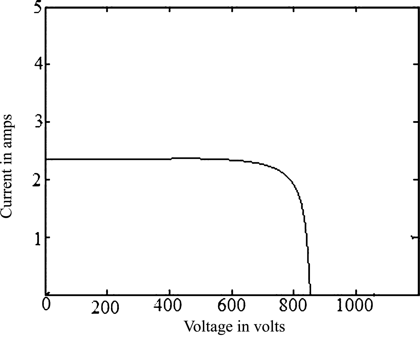
(a) Voltage vs. Current Characteristics of Solar PV.
The four inputs to the fuzzy engine are the wind, solar demand at load and the SOC of the battery. These variables are fuzzified and fed as input to the fuzzy engine. The universe of discourse of all these variables are segmentised into three segments with triangular membership functions.
There are two output variables and they are the duty cycle for the boost converter and the charge control circuit. Since there are four input variables with three membership functions there will be a total of 3*3*3*3 = 81 rules
Figure 17 shows the DC link voltage at steady state and it is nearly 500 v. In this work there is no provision or control system necessary to maintain the constancy of the DC link voltage, because of the following two reasons.

Time vs DC Link Voltage.
a. The battery is connected across the DC link and being a sink the battery is strong enough to keep the DC link at its terminal voltage with only some nominal voltage variations with respect to the State Of Charge of the battery.
b. At the load side is a three phase inverter operated with SVPWM strategy with closed loop system to maintain the three phase AC terminal voltage.
Because of these two reasons the DC link voltage is not regulated to be a constant one.
Figures 18(a) and (b) give a clear picture of battery charging and total current. When it is subjected to a constant charging current. As time passes on the with constant current charging at 21 Amps the SOC of the battery rises slowly. In Fig. 18(a) the time scale is in terms of seconds and the y axis shows that the SOC rises and since the time considered is so small the numerical value of SOC seems to be a constant, even though qualitatively it rises.
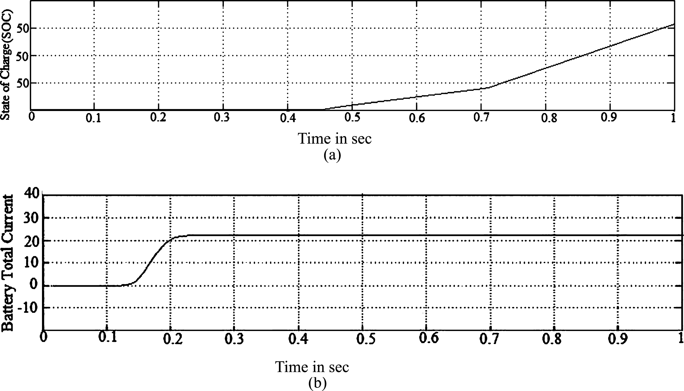
(a) Time vs State of Charge (SOC). (b) Time vs Battery Current.
In Fig. 19(a) and 19(b) the variations of charging the battery is indicated with respect to different wind velocities. However, the demand across the load terminals is the same. With a constant demand, but with changing wind velocities it is the charging of the battery that changes and not the load. SVPWM is employed in the final load side inverter.

(a) Time vs Battery charging current for load demand 8 kW. (b) Time vs Battery discharging power for load demand of 12 kW.
The three phase inverter is the ultimate power output terminal since the load catered is a three phase R L load. In order to ensure better fundamental output voltage and reduced harmonics the space vector PWM (SVPWM) is used. The basic sub systems of the SVPWM section comprises of the Alpha Beta conversion, reference rotating space vector formation the segment identification and the dwell time calculation. The pulses for switching the power MOSFETS are derived from the SVPWM pulse generator unit. The pulse for two switches are shown in Fig. 20.
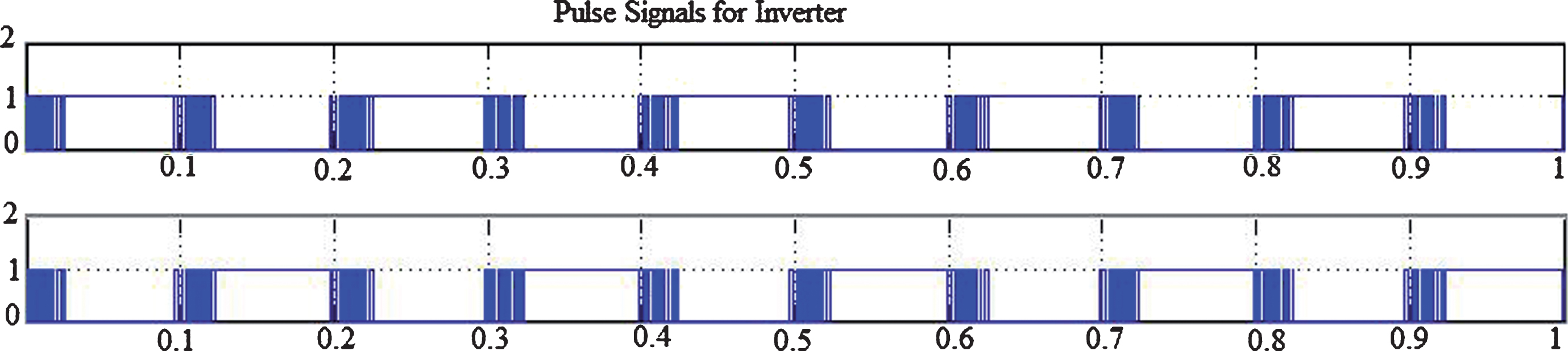
Switching signals for inverter.
Figure 21(a) (b) and (c) show the AC terminal voltage the three phase load current and the FFT of the load current. All the harmonics are well below the 5% benchmark and the THD of the three phase load current is just 2.23%.

(a) Load Voltage. (b) Load Current. (c) THD value for load current.
The following Tables 4 and 5 shows the power balance for the given wind solar conditions and the loading conditions.
Load Demand = 8 kW
Load demand = 12 kW Wind, solar for different conditions
For comparison the system was simulated with FLC and the result obtained by simulation has revealed that the proposed ANFIS controller is superior to the existing fuzzy logic based controllers and a quantitative comparison of the performance in power flow and power quality has been presented in Table 4.
The value of the integrated square error as obtained from the FLC and the ANFIS have been presented and the results show that in terms of ISE as well as the ripple content in the DC link the ANFIS method of control is more promising than the FLC as indicated in Table 5.
In the hybrid wind and solar system have lot of limitations and hence a novel hybrid wind and solar power for MPPT controller using ANFIS based standalone critical load has been presented in this paper. The wind and solar power generation system were provided respectively with ANFIS and IC (Incremental Algorithm) based MPPT systems. The power flow control from the sources to the load as well as the battery has been managed by an FLC based control system.
The MPPT, the power flow and the battery charging have been carried out in a seamless manner with optimal power flow. The system is so complicated with multiple power sources with unpredictable power capabilities, requiring MPPT under varying environmental conditions. However, with the advanced soft computing techniques the task has been handled efficiently meeting with the appropriate power quality requirements. The system consists of a number of power electronic converters. A large number of parameters are to be considered in deciding the duty cycles of the various converters. It is suggested that as a future development a comprehensive all inclusive control system in the VLSI platform be implemented for the management of the whole system. In future the presented work can be extended for microgrid applications.