
Abstract
The traditional algorithms reduce the recognition accuracy because of the influence of the fluctuation of the camera position during the walking of the robot. For this reason, a new intelligent recognition algorithm for color vision image position of soccer robot is proposed. The structure of the soccer robot vision system is designed. The panoramic visual sensor VS-C450 N-RC and the image acquisition device based on the IEEE 1394 standard are used to obtain color visual images, and the acquired distorted images are processed. Comparing color patches, an effective color patches scheme is proposed based on practice. RGB space is converted into HIS space, color, saturation and brightness are used to represent colors. According to the principle of contour extraction, an effective color patch extraction and recognition algorithm is proposed to match the robots on the actual field so as to obtain information such as the position of the soccer robot. The pose information of the robot is represented by the pose information of the color patches, and the position of the color visual image of the soccer robot is determined. Experimental results show that the proposed algorithm has high recognition accuracy.
Introduction
The robot soccer game is a multi-intelligence system development platform proposed in recent years. It is a typical multi-intelligence robot system [1] and an high-tech intensive project with extremely challenging in the field of artificial intelligence and robotics. At the same time it is an ideal breakthrough point for multi-intelligence technology and the second milestone in the development of artificial intelligence that emerged after computer chess [2]. It involves technologies in various fields such as computer vision, pattern recognition, multi-sensor information fusion, decision strategy, wireless digital communication, automatic control and optimal control, artificial intelligence, mechatronics, etc. It is a standard experimental platform for the study of multi-intelligence systems [3]. The visual system is the only way for soccer robots to obtain external information. Therefore, the intelligent identification of the position of color visual images of soccer robot is the key to the entire system.
In recent years, visual sensors have received widespread attention because of their rich environmental information. The adoption of intelligent recognition for visual image position has also become a research hotspot as well. Many scholars have proposed different identification algorithms, mainly including the following:
Sadeghzadeh proposed a position recognition algorithm based on stereo vision [4]. This kind of algorithm can get more information about the surrounding environment and get more accurate recognition results, but it needs to solve the matching problem of feature points in stereo vision. The Sabnis reported a position recognition algorithm based on panoramic vision sensors [5]. The use of visual sensors does not require the control of the camera, but it will cause great distortion in the perceived environment. Guarnizo et al. came up with a position recognition algorithm based on monocular vision [6]. This algorithm is easy to use and has a wide range of applications, but it is difficult to obtain high positioning accuracy by using this method directly.
In the vision positioning system of fully autonomous soccer robot, multidimensional hybrid vision positioning technology is widely used. A robot vision system composed of panoramic vision and forward vision is designed, and the recognition result obtained has high precision [7]. Talab brought up a calculation model for monocular vision two-dimensional space transformation that suitable for a fully autonomous soccer robot [8]. The computational model solves the two-dimensional spatial plane mapping problem between the monocular visual image plane and the actual site plane, and achieves a more accurate target position determination. Also, Cano el al. proposed a multi-dimensional vision system to realize the position recognition of soccer robots [9]. The algorithms described in the above are all proposed for medium-sized soccer robots. The competition system does not limit the number and position of cameras. However, due to the fluctuations in the position of the camera for the humanoid soccer robot during walking, the recognition accuracy is affected.
In view of the current research situation of the soccer robot’s position recognition, a new intelligent recognition algorithm of the color visual image of soccer robots is proposed. The color visual image of soccer robots is collected and preprocessed, and color information library is established by color calibration, and the color patches recognition can recognize the color visual image position of soccer robots.
Material and methods
Soccer robot vision system structure
The soccer robot vision system is composed of image acquisition hardware and image processing software. The hardware includes a panoramic vision sensor VS-C450 N-RC, fixtures, an image acquisition device based on the IEEE 1394 standard, and a USB digital camera. The software part must realize the functions such as image preprocessing, image segmentation, feature extraction and position intelligent positioning. The robot entity is shown in Fig. 1.

Stereogram of the soccer robot.
The panoramic vision sensor is a kind of vision sensor that uses a single camera to obtain a full range of environmental information. It uses a mirror to reflect the full environment, and then enter the sensor for imaging. Reflectors have a variety of surface shapes such as hyperboloids, paraboloids, spheres, and cones. The panoramic vision model in Fig. 1 uses a reflector with a hyperbolic surface, and the forward vision sensor adopts an ordinary pinhole camera, which uses the USB interface to directly obtain the digital information of the image and simplifies the visual processing. System software is designed using a software structure based on interprocesscommunication [9].
Panoramic image acquisition
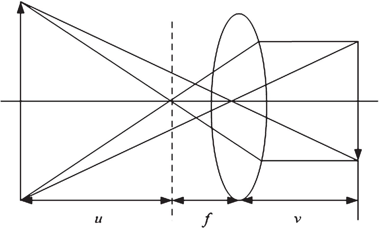
In machine vision, the image acquisition process mimics human vision. In the robot’s vision system, imaging is done primarily through the lens. The acceptance of the signal is mainly through the light sensor, and then the digitized instrument digitizes the signal. Lens imaging is based on geometric optical schematic diagram, the following convex lens imaging formula is used:
In the formula, f is the lens focal length, that is, when the incident light is parallel light, the distance between the lens and the convergence point; u is the object distance, that is the distance between the object and the lens; v is the distance between the lens and the real image, as shown in Fig. 2.
Lens imaging model.
To acquire digital images, two devices are required: one is a physical device (sensor) sensitive to a certain electromagnetic energy spectrum band [10]. Another is called a digitizer. All devices that collect digital images require both devices. This section uses the panoramic vision sensor V S-C450 N-RC and image acquisition equipment based on the IEEE 1394 standard.
The process of obtaining an image is divided into two parts:
The image is converted from an optical signal to an electrical signal. This part is implemented by the panoramic vision sensor V S-C450 N-RC. The analog signal changes to a digital signal. This part is completed by an image acquisition device based on the IEEE 1394 standard. The output signal of the camera used by the general soccer robot vision system is a color video signal. The image acquisition device decodes the color video signal to obtain RGB three-way analog signals, then performs A/D conversion on the three-way analog signals respectively, and finally obtains a color digital signal.
During the image acquisition process, since the analog video input can provide an uninterrupted source of information, the acquisition device must collect each frame of the image in an analog video sequence and send the data to the PC system before acquiring the next image. Therefore, the key to achieving real-time acquisition is the processing time required for each frame. If the processing time of each frame is more than the time interval between the adjacent two frames, the data will lost, that is, the phenomenon of losing frames. The acquisition device first compresses the acquired video sequence and then stores it in the hard disk. That is, the acquisition and compression of the video sequence are performed together, eliminating the inconvenience of performing compression processing again.
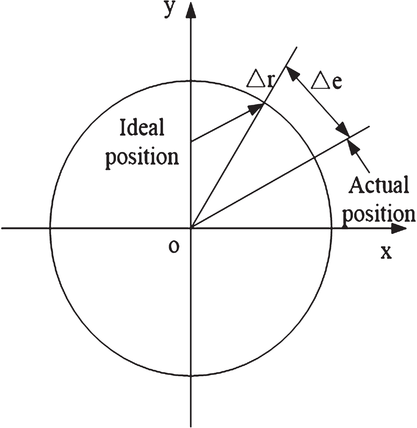
During the imaging process of the frontal panoramic vision system, the circular surface mirror reflects the light from the target and projects it onto the imaging plane after passing through the optical center of the camera [11]. Each camera can meet the principle of pinhole imaging because of its own lens. b However, due to the processing error and assembly error of the lens, there is a certain degree of deviation between the actual image points and the theoretical points. In order to get the correct position information in time during the game, it is very important to process the acquired distorted images. This is very important for the location intelligent recognition of color vision images of soccerrobot.
It is generally believed that lens distortion is mainly composed of the radial error Δr and the tangential error Δe, as shown in Fig. 3.
Schematic diagram of distortion error.
The radial error is generally considered to be caused by the error of the Biomn’s curvature of each group of lens. Its mathematical model is:
In the formula, φ2 = (x - x0) 2 + (y - y0) 2; h1, h2, h3, ⋯ is the radial distortion system; (x0, y0) is the coordinates of the center point of the imaging plane; the radial distortion coefficient is determined by the function related to the focal length f.
Radial distortion is dominant in most optical systems, as shown in Fig. 4.
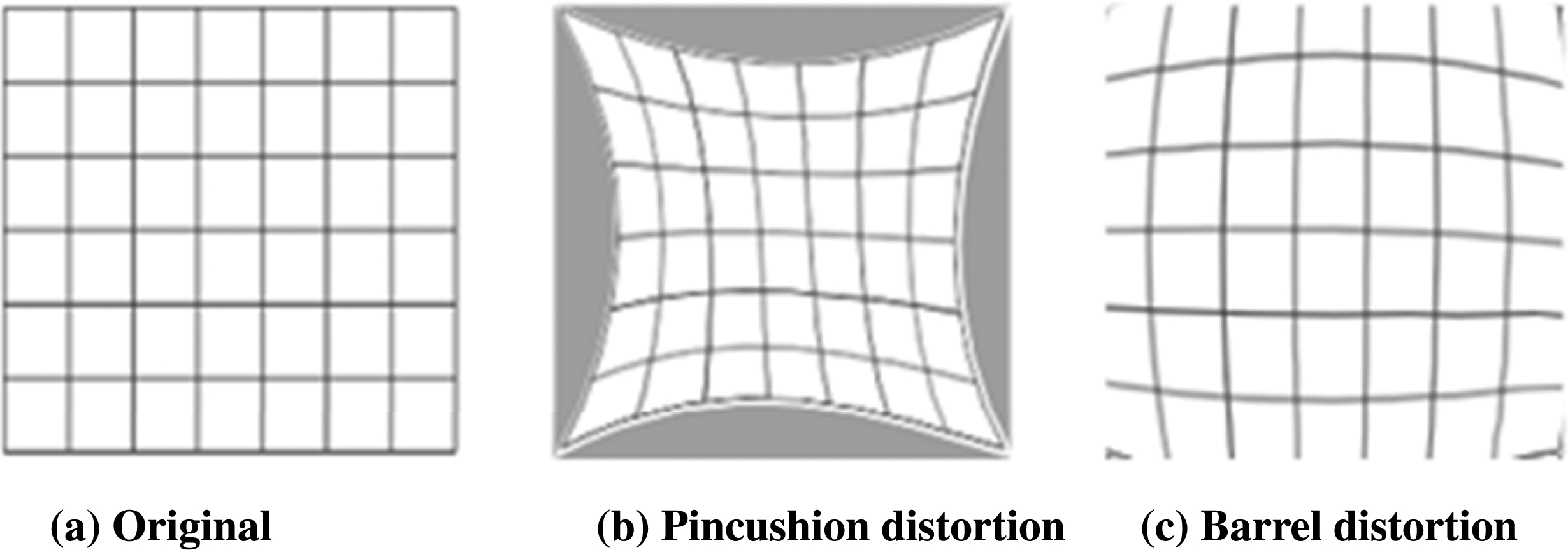
Radial distortion.
The tangential error is generally considered to be caused by the non-collinearity of the optical centers of the lenses. The mathematical model is:
In the formula, q1 and q2 are tangential distortion coefficients.
The total error can be expressed as:
The short-focus wide-angle lens is used in the vision of soccer robots. In the short-focus optical lens, radial distortion mainly exists, and the tangential distortion is relatively small. Usually only radial errors are considered, so the lens error expression can be simplified to:
Comparison of the color patch
The color of the soccer robot is determined by the team color (the main color mark) and the ID color (the auxiliary color mark). The team logo is the foundation rule and is selected as yellow or blue. The team color markers are selected by themselves. The color patch scheme is as shown in Fig. 5, wherein Fig. 5(a) and 5(b) are common icon schemes.
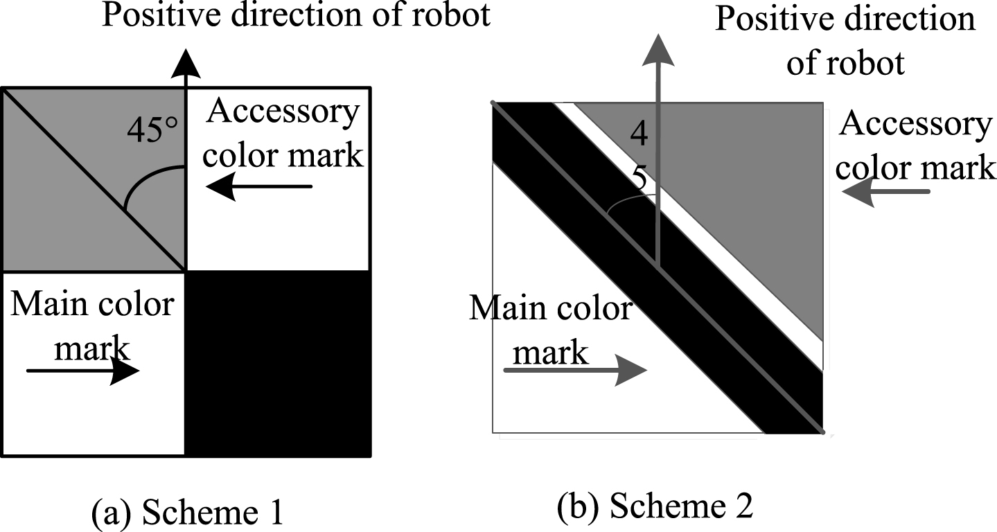
color scheme.
The scheme of Fig. 5(a) has the two colors, as the main and sub color patch, and 2 color patches are square, the center point of the 2 color target connection is the center of the center point of the robot. The direction is that the middle point of the main color mark points to the middle point of the secondary color mark and then rotates 45 degrees clockwise. However, it has a very important drawback. Adhesion occurs when two robots are together, as shown in Fig. 6(a). In the rules of the soccer robot game, the collision of cars is allowed, and there are many opportunities for collisions, that is, many misjudgments. Obviously, this scheme is not ideal.

Analysis of the color scheme.
The scheme of Fig. 5(b) is mainly determined by the main color patch, which divides the main color patch into two parts. As shown in Fig. 6(b), the center point of the two parts is obtained by dividing and compensating the approximation method. The middle point of the point connection is the center point of the robot, and then the direction of the robot is determined by the secondary color mark. Its advantages are high accuracy and strong anti-interference ability, but the calculation is complicated. This is inconsistent with the requirement of high real-time performance, which leads to slower operation speed.
After theoretical analysis, an ideal color scheme is adopted on the basis of practice, as shown in Fig. 7.
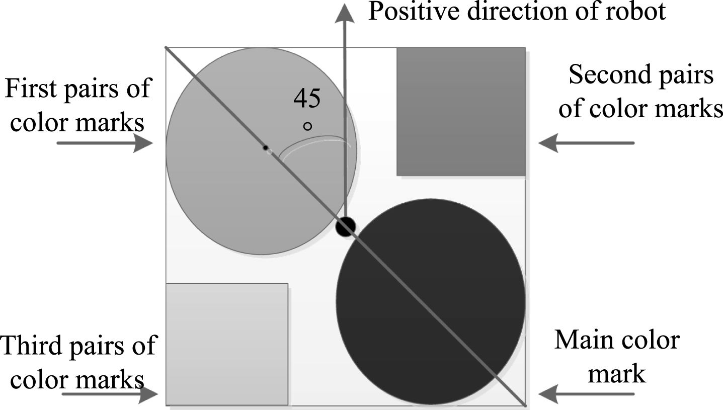
The chosen ideal color scheme.
The center point and direction of the robot are determined by the team color and the first ID color, while the second ID color and the third ID color play an auxiliary role in determining the number of players. The main color patch and the first sub-color patch are circles with the same diameter, the center of the circle is on the foot of the robot, and it is tangent to the other two sides. The center of the robot is at the midpoint of the line connecting the two centers, and the direction of the robot is the main color patch. The direction of the robot is that the center of the main color standard points to the vector direction of the first pair of color patches and then rotates clockwise 45°, that is:
Its advantages are:
The algorithm is simple and reduces the amount of calculation. Because the color patch has dispersion in strong light, the circumference of the circle is the smallest when the area is equal, so the dispersion is also the smallest. The area of 2 circles is the same, so the influence are the same, so that the correctness and stability of the robot center and direction can be ensured when the light intensity changes. The 2nd and 3rd color patches are 2 equal squares. In the square pattern, their dispersion is the smallest. The purpose of adding them is to reduce the type of color because the second and third color patch can be defaulted when it is not necessary, so that even in the 7:7 competition, we only need 4 colors (1 main color patch, namely the team logo, and 3 other sub color patches). It is obviously better than the 8 in the previous plan.
The most common color space is the use of R, G, B to constitute a two-dimensional space to represent various colors, and the advantage of using the RGB color mode is that the calculation is simple and does not require conversion [12]. However, it has a strict flaw that is vulnerable to the impact of light intensity, due to different environments and different locations of the competition venue, the light intensity has a great change, making the same color RGB value in different positions have a greater change. Therefore, the color cannot be judged by a single threshold.
In order to avoid the above disadvantages, this section converts RGB space into HIS space, that is, use chromaticity, saturation, and brightness to represent colors. Its conversion formula is:
Then find the values of H, I, and S from y, d1, and d2:
The HIS values obtained were all normalized to the range of 0–255 [13]. Among them, H represents the angle, each color has the corresponding value, according to H value, the corresponding color can be found, it is the red near 0 or 255, is purple near 210, and is blue near 170.
Recognition algorithm of the color patch
Color patch identification is the key to the intelligent recognition algorithm for color vision images of soccer robots. In this section, effective color-patch extraction and recognition algorithms are selected. The algorithm is based on the principle of contour extraction. The color patch refers to the contour image obtained by contour extraction and the enclosed area. All color patches and color patches consist of multiple pixels. The outline color patches are denoted by the matrix A = (a1, …, a n ), the identified color markers are the matrix B = (b1, …, b n ), and the thresholds are denoted by the matrix O = (o1, …, o n ), wherein the matrix O is simply calculated from the matrix B. Extracting the color patches can be attributed to finding the matrix A that satisfies the condition |A - B| < O from the known matrix B and O.
When extracting the color patch outline, the rule is: From the first outline point (entry point) Z, it is judged whether it is a color point, and if so, the search direction is defined as left; if not, the search direction is defined as right. The search direction here differs depending on the current angle.
The effective color patches are the patches corresponding to the motion entities in the actual field in the court scene image [14]. The effective color patches are extracted to match the robots and balls on the actual field to obtain information such as the position and direction of the robot and the position of the ball. Briefly introduce its implementation steps as follows:
Select a suitable scanning grid to perform grid search on color visual images. Search for entry points. Determine if the scanned pixel satisfies |A - B| < O. If it satisfies, it is the boundary point. If it is not satisfied, continue to scan until it meets |A - B| < O. After finding the boundary point, search in the direction of the left side of the point and judge whether it is the boundary point one by one until the non-boundary point. At this time, the non-boundary point is recorded as the pointcut Z, and the point on the right is recorded as the current point C. Extract color patches. Using color image-based contour extraction, all color patches in the image are obtained. Record the important information such as the maximum and minimum values of the abscissa and ordinate of each color patch, the edge points and their number, and obtain the distribution of the color points of the patch, which provides the basis for the next step. Filter noise patches and repeat patches. Through a certain judgment basis to filter out the noise color patches, calculate the color patch area and center coordinates, then filter out the repeated color patches to extract effective color patches.
Pose parameter calculation
The pose information of the robot is represented by the pose information of the color patch. The pose of the color patch includes two parameters of the center point coordinate and the direction angle of the color patch, and the calculation method of the pose parameters is depend on the design scheme of the color patch [15–17]. For the color patch design, the center point of the team logo is the center point of the color patch, and the long axis of the team logo is aligned with the player logo to obtain the orientation angle of the color patch.
The center point of the team logo is obtained.
Because of the symmetry of the team logo on the color patch, the team logo center can be obtained directly through statistical methods. Let (x0, y
o
) as the center point coordinate, then (x0, y
o
) can be obtained by the following formula:
Among them, (x
ij
, y
ij
) is the coordinates of the pixel points in the target area that match the color of the team logo, k, l are the size of the target area, and N is the number of pixels in the target area that match the color of the team logo feature.
To obtain the angle of the direction of the long axis of the team logo.
There are many methods for obtaining the long axis orientation angle of the team logo, such as the least squares straight line fitting method and the shortest line segment method. These methods all have problems that are greatly affected by noise. Due to the divergence of the color patches and the interference of the channel noise, the identified color patches are unstable, and the calculation results oscillate back and forth. This result is extremely unfavorable for the decision. There are some methods that can accurately produce results, but they cannot meet the requirements of real-time system. The basic implementation of the method used in this section is to use the central symmetry feature of the team logo to divide the center point into two symmetrical parts along the x-axis or y-axis, and to obtain the centers of the two parts, respectively. And the direction of the connection of the two center points is the approximate value of the direction angle of the team logo. Taking the x-axis division as an example, the center points of the two parts of the team logo divided by the x-axis are obtained by A1, A3, A4 and A2, A5, and A6, respectively. The actual direction angle should be determined by the center determined by A1, A3, A5 and A2, A4, and A6, so there is a large error in the approximate value obtained. The regions A3′, A4′, A5′, and A6′ are segmented using the normal line of the currently obtained approximate direction angle, and then a direction angle is recalculated using A1, A3′, A5′ and A2, A4′, and A6′. The obtained by the compensation algorithm is an approximation closer to the exact value than

partition of the team logo.
In real-time applications, the number of compensations can be taken from 1 to 2 times. At this time, if the identification result is full, the calculated angle deviation should not exceed 1°. The specific algorithm is as follows:
In the formula, (ν
x
, ν
y
) and (g
x
, g
y
) are the center coordinates of the upper and lower halves of the x-axis, ∑x
Ai
and ∑y
Ai
are the x-coordinates and the y-coordinates of the points of the region Ai (i = 1, 2, 3, 4, 5, 6) that match the color of the team logo feature, and n
Ai
is the number of points of the area Ai that conforms to the feature color of the team. From the center point of these two parts, the approximate direction angle can be obtained:
The calculation of the actual direction angle: The actual direction of the calculation team logo should be determined by the center points of the areas (A1, A3, A4) and (A2, A5, A6). The normal divided areas (A1, A3′, A4′) and (A2, A5′, A6′) of the approximate direction angle are compensated to determine a more accurate direction angle. So there are:
The center point of the two regions after compensation can be obtained:
Thus, a more accurate direction angle can be obtained:
To get more accurate results, you can make to get that is closer to the exact angle. Taking into account the need of real-time, only one compensation is made, and the error has been less than 1°, which fully meet requirement of location intelligent recognition precision of color vision image of soccer robot.
Sample data collection
The experimental platform is the Robo Cup medium-sized MT-R autonomous soccer robot. The camera uses security surveillance color camera Watec WAT-250D, it outputs NTSC standard video signal, and constitutes a panoramic vision system through the combination of hyperbolic mirrors. The image acquisition frequency is 30 frames/s and the resolution is 640×480. The central processor of the soccer robot is Intel Pentium(R) 4 CPU 3.00 Hz and the operating system is Windows XP.
Sample selection and pretreatment
The image is pre-identified, targets and interfering objects that are still unrecognized are intercepted in the original image as candidate target samples. The area of the ball in the panoramic image is relatively small, and intercepting an image of 32×32 can meet the requirement. Using the above method, 800 panoramic images of soccer robots and interfering objects under different lighting and different positions were collected, and 600 images of target or interfering image were intercepted. The target image was used as a positive sample and the interfering image was used as a negative sample. According to the ratio of 2:1, the images were divided into training samples and test samples. Figure 9 shows a sample selection diagram in a panoramic image.
Sample selection.
For ease of analysis, the interference target is removed, the color design of the robot is performed, and the robot with the target color on the top is moved from the right half field to the left half field, and the sample image is subjected to differential processing, as shown in Fig. 10. Figure 10 (a) is a sample image, that is, a moving image of a robot. There are three target colors in the box, which are yellow, purple and green from top to bottom. Figure 10 (b) shows the image when the robot starts to move. Figure 10 (c) is the differential image of two images, the color patches scattered in the upper left, upper right, and lower right areas of the image are non-target color patches.

Sample image preprocessing.
After preprocessing the sample image, as shown in Fig. 10(c), the non-target color has been completely filtered out, and the threshold is set to divide the image in Fig. 10(c). The result of the segmentation is shown in Fig. 11. The results are yellow, purple, and green.
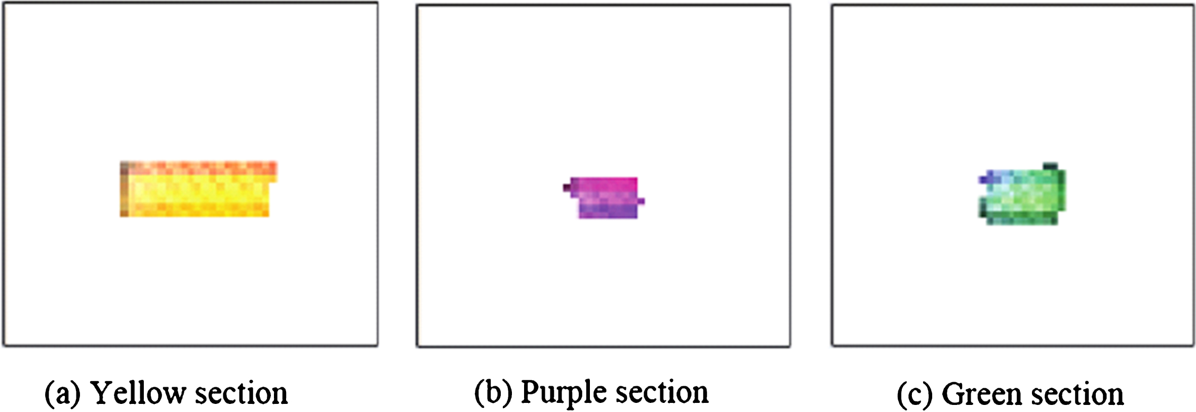
Segmentation of sample images.
Through segmentation, the computer accurately finds the area where each target color is located, then performs feature extraction on the target color, and the calibration process ends. Experiments show that by using image difference processing, the calculation can accurately find the target color area.
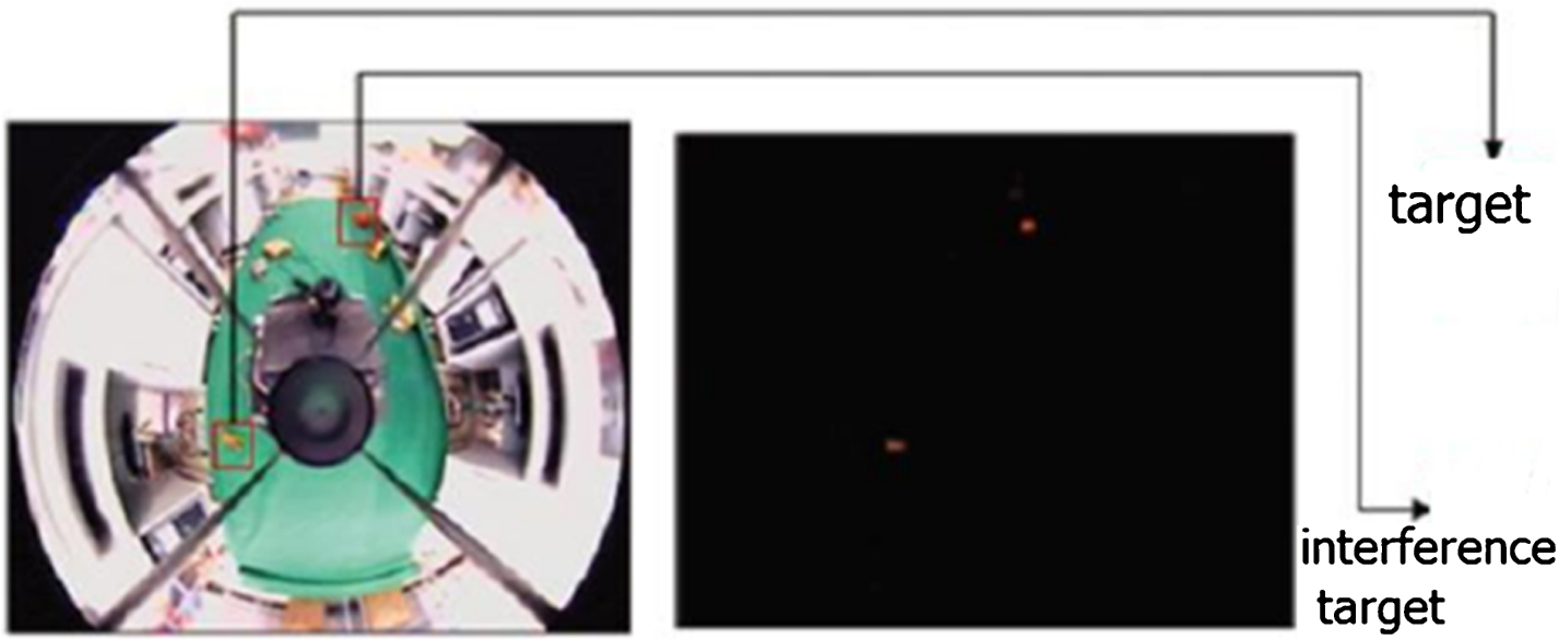
In order to better verify the robustness and practicability of the proposed algorithm, the proposed algorithm was tested and compared with the algorithms proposed in literature [6] and [7]. The sampling frequency of the robot is 20 frames/s. First, fix the position of the robot, change the light, and count the target position identified by the robot vision system; keep the light the same, let the robot move to the football at a speed of 0.02 m/s along the straight line, and count the robot’s color time image position recognition result to get the recognition rate. The recognition result is shown in Fig. 12. Figure 12(a) identifies three similar target locations, which are soccer, robot and box, respectively, which are marked with red boxes in the figure. In Fig. 12(b), the box is filtered by the simple shape feature, but the robot and the ball are still indistinguishable. Figure 12(c) accurately identifies the target position by the proposed algorithm.

Real-time recognition results.
Table 1 compares the recognition accuracy and processing speed of the three recognition algorithms. The algorithm proposed in literature [6] has a faster processing speed and can reach 26 frames/s, but the recognition rate is very low. It can also be seen from Fig. 12(a) that it is not easy to identify the target position. The algorithm of literature [7] can filter out a part of the interference target, the recognition rate is greatly improved, but the speed cannot meet the real-time requirements of the robot game, and there are still cases of misidentification. The recognition rate of this algorithm reaches 93.6%, and the recognition effect is the best. The processing speed can meet the real-time requirements of the robot game.
Comparison of the recognition results and processing speed with three algorithms
The research content of this study mainly focuses on the following aspects:
The first is the acquisition and preprocessing of color time images of soccer robots, which provides the basis for intelligent recognition of subsequent positions. The second is the color design research. The design problem of color patches has always been a difficult problem in the design of soccer robot vision systems because the color patch design and identification algorithms are closely related. A good color patch design can not only improve the identification accuracy, but also improve the real-time and anti-interference of the system. The last is the study of the color identification algorithm. In the soccer robot game, soccer robots identify the position, direction and number through the top of the color identification robot. In order to improve the recognition performance, a fast identification algorithm based on the hull rectangle is proposed to determine the position of the color image of the soccer robot.
As one of the research hotspots in the field of artificial intelligence and robotics, the research of soccer robots has been rapidly developed in recent years. With the deepening of research and the development of related technologies, it is bound to put forward higher requirements for its various subsystems. For the soccer robot vision system, the work done in this study lays a foundation for the further improvement of the visual system.
Footnotes
Acknowledgments
Project plan of key scientific research in Henan University.