
Abstract
Speed control of synchronous machines using Field Oriented Control (FOC) classically uses Proportional Integral (PI) or Integral Proportional (IP) regulators that allow to achieve satisfactory goals on the dynamics of speed and torque. However, the performance deteriorates with loss of one or more phases in multiphase machines with IP regulator. This paper present comparison between the use of IP regulator and Fuzzy Logic Regulator (FLR) under same conditions applied to Five Phase Permanent Magnet Synchronous Machine (FPSM). First, modeling and performance of the FPSM are presented. In the beginning, the control is ensured in healthy mode with an IP regulator then in degraded mode when one then two phases are opened. The performances of the FLR are compared to IP ones. Better performance of FLR is established in terms of faster dynamics.
Introduction
Particular applications like electric vehicles, wind or marine current turbines and ships propulsion, require a great reliability of on-board equipment. The revolving machine is the heart of these applications and it is sometimes desirable even essential to keep its operation even under severe conditions where a defect emerges, and the intervention becomes risky or too expensive.
A certain number of these applications then betted on the training system by supporting the polyphase machine where number of phases is higher than three, it offers a certain number of additional freedom degrees when we compare it to the classical three-phase machines [1].
These freedom degrees can be exploited to improve the Torque density [2], or to control several machines with their stator windings connected in series or parallel [3] or to maintain a certain operation during the degraded mode at time of effect or fault.
A defect or fault in an arm of inverter or in its connection with the polyphase machine generally leads to degradation by rupture of a stator phase. It is the most common fault in machine-converter association [4], this causes the annulation of the current in the corresponding phase and thus the appearance of a pulsating torque. The development of command which maintain a constant torque is more than necessary.
Previous work already led to solutions for the opening phase [5–7]. In these works, a new model is prepared according to the imbalance supply caused by the loss of one phase. New current references are then established minimizing joule losses. The associated control can be insufficient especially when certain dynamic characteristics are restricted.
One idea consists on using control insensitive to disturbance and nonlinearities such as intelligent techniques. The intelligent techniques based on fuzzy logic didn’t stop showing their performances and their effectiveness and several works confirm it since work of Mamdani in 1974 [8].
Contrary to the classical regulators, the adoption of a fuzzy logic regulator in speed loop does not require a precise mathematical knowledge concentrated around the process, but it requires a base of several rules calling on linguistic variables. An expert feeds this base by preliminary data, by envisaged or desirable results.
Although the mathematical models of the electric machinery are known and the conventional regulators are always present in most of the control loops, their use becomes limited in case of sudden change of machine model, this change can be related to the parametric variations or accidental opening of one or more phases supply.
For this purpose, a new method of five phase synchronous machine FPSM control is presented. This method is based on fuzzy logic theory which enjoys a dominating place in the active world of research going from signal treatment until machines control and associated converters.
This theory started in 1965 when Professor Lotfi Zadeh published his article “Fuzzy set” [11, 13]. It did not find an echo at the beginning, but it started to be spread on a great scale and its first applications touched the systems of adjustment and control in the industrial world thanks to a purely scientific print. Fuzzy logic is used in several applications ranging from home appliances control [14, 15] to three-phase machines control in healthy [16] and faulty mode [17] and even to multiphase machines control [18–20].
Initially, the model of the FPSM is presented and its operation in healthy mode then a comparative study between the use of a classical IP regulator and a FLR will be drawn up by underlining the contribution of fuzzy logic at the time of the loss of the initial model of the machine.
The results of simulation carried out under Matlab/Simulink is presented and discussed in order to check the performances of the adopted regulator.
Modelling of the five-phase pmsm
The mathematical modelling of the FPSM is considered simple owing to the fact that matrix (1) of inductances connecting flux resulting from theelectromagnetic coupling to the currents comprises only constant terms, L being the self-inductance of a phase, m1 mutual inductance between two shifted phases of 2 . π/5 and m2 mutual inductance between two shifted phases of 4. π/5.
Classically, for three-phase machines, a basic change entirely solves the problem of the adjustment model; it is the same for the FPSM. By the transformation of Concordia (2) preserving the power, one establishes the system of equations (3) where R is the resistance of a phase, Vα1β1, Iα1β1 and φ
r
α1β1 are respectively projections of the voltages, currents and flux on a first plane P1 = α1β1, while Vα2β2, Iα2β2 and φ
r
α2β2 are their projections on a second plane P2 = α2β2.
The Field Oriented Control (FOC) of the FPSM in normal mode is established by applying the Park transformation to each fictitious machine according to corresponding electrical angle (θ e for the principal fictitious machine and – 3θ e for the secondary fictitious machine). It is possible to control the FPSM by using a classical PI regulator [10]. The IP regulator used in speed loop is different from PI regulator by the fact that it does not present a zero in the transfer function in closed loop, thus it will not have an impact during application of load.
In general case, the IP regulator diagram block used with first order system is illustrated in Fig. 1. Block diagram of speed control using IP regulator.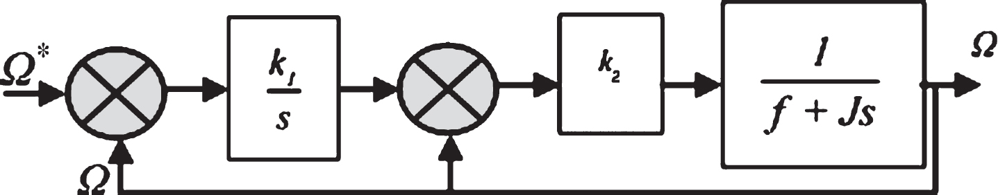
The closed loop transfer function is given by (6), where k1 and k2 are respectively integral and proportional gains of IP regulator, they are adjustable parameters allowing to impose a particular dynamic, especially noting that the closed loop transfer function corresponds to a second-order transfer function (7) coefficients.
After identification, one can choose k1 and k2 so as to impose a damping ratio m equal to 1 and a natural frequency ω
0
allowing quick response.
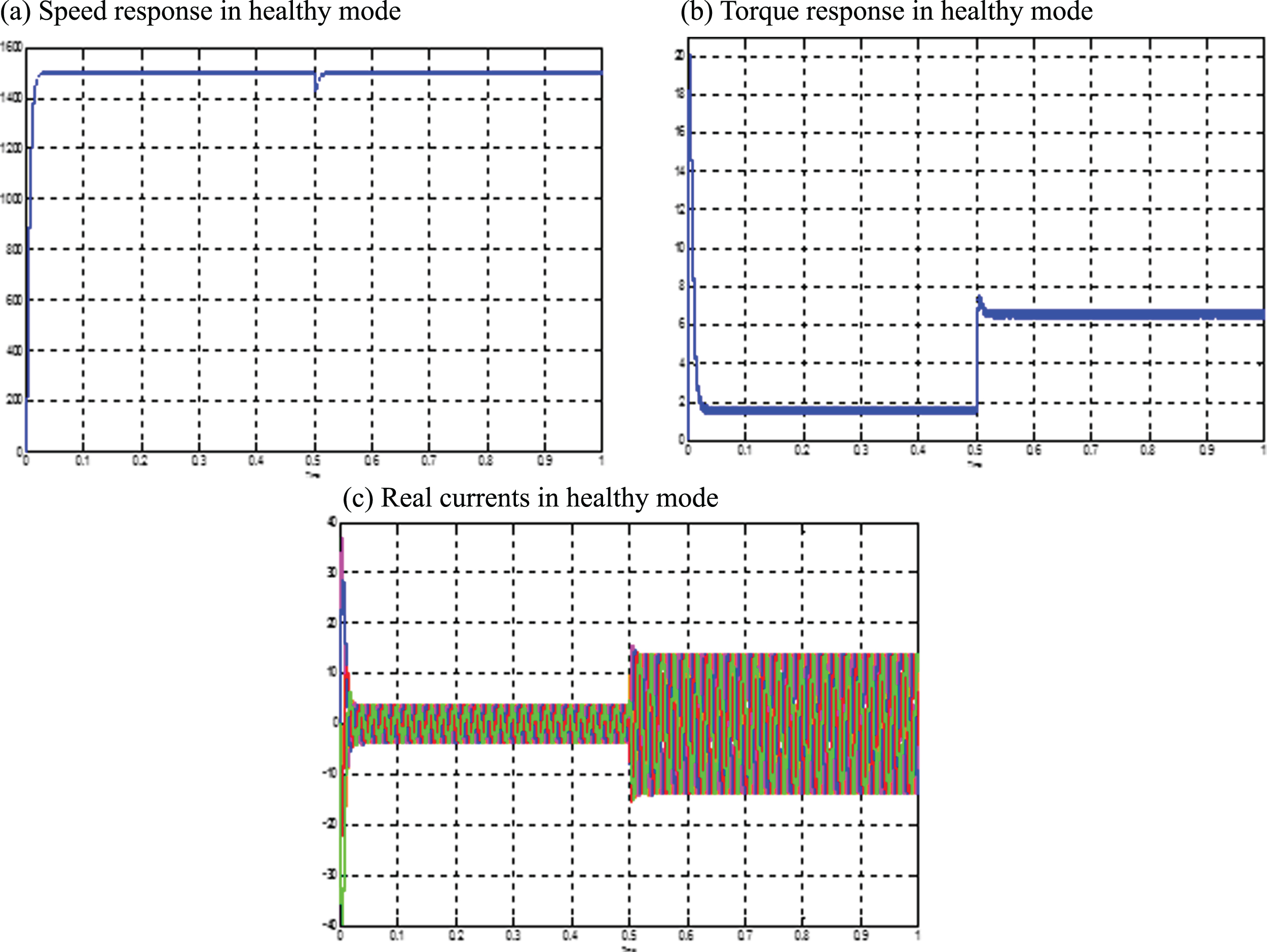
The topology of the FPSM control is given in Fig. 2 and simulations were observed for the operation of the FPSM to which a 5Nm load is applied at 0.5 s. The FPSM is fed through an five arms inverter and controlled by space vector pulse width modulation technique using four vectors per sector [9]. Speed and torque machine are given in Fig. 3a, b respectively. Figure 3(c) gives currents in each of the five phases, they are all present, an increase in their intensity at the moment 0.5 s is announced in order to make it possible torque machine to overcome the torque load. Topology of FPSM control using IP regulator. (a) Speed response in healthy mode. (b) Torque response in healthy mode. (c) Real currents in healthy mode.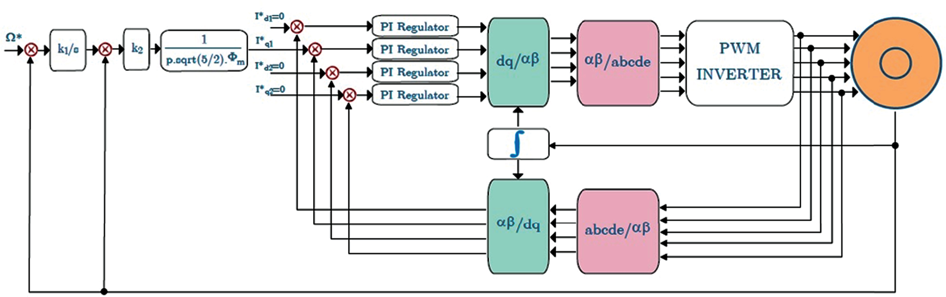
Fuzzy logic control
In fuzzy control systems, one can distinguish three principal parts: the fuzzification where one define for each system input a speech universe and a partitioning of this universe in vague units, then a mechanism of inference calculates the fuzzy subset relating to the control of the system while being based on a basis of linguistic rules initially defined by an expert [12]. Finally, the defuzzification which transform the fuzzy subset into a non-vague value allowing the effective control of the system. For the case of the FPSM, we define to the fuzzy regulator two input variables: the speed error “e” and its variation “de” (Fig. 4).
To obtain a better control results, a database of 49 rules can be summarized in Table 1 where seven membership functions are defined for each input, they are noted as follows: Topology of fuzzy regulator.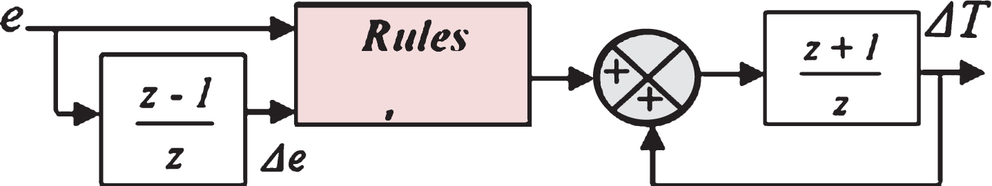
NL: Negative Large
PL: Positive Large
NM: Negative Medium
PM: Positive Medium
NS: Negative Small
PS: Positive Small
ZE: Approximately Zero
These fundamental seven kinds of fuzzy variables are used to be able to describe, in a linguistic way, the state of the error and its variation. Membership functions used with speed error and its variation are triangular form as shown in Fig. 5, the fuzzification method adopted is the max-min method and the defuzzifiation method centroid method. Fundamental seven membership functions.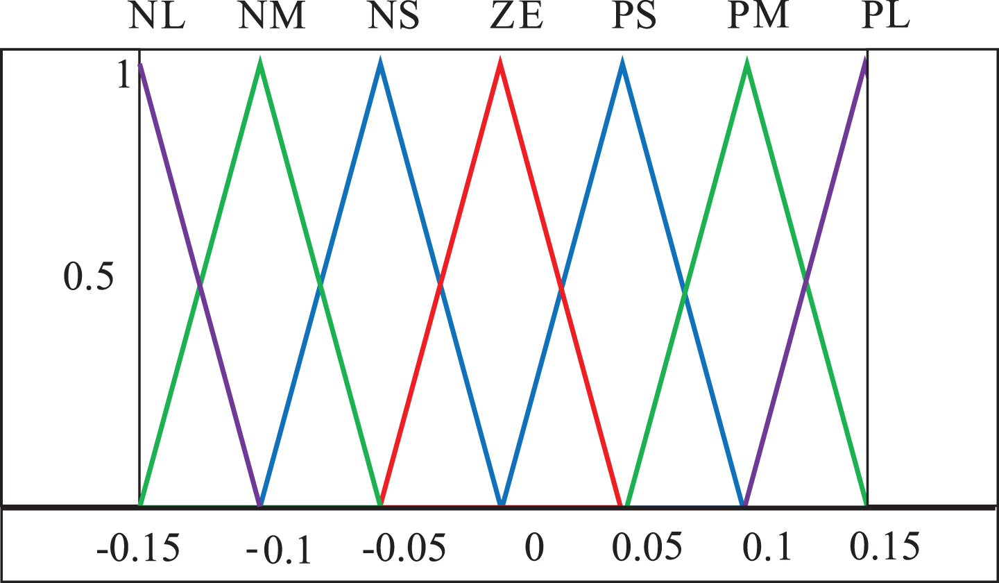
In order to compare classical and fuzzy regulators IP, initially the simulation is done for the operation of the FPSM in healthy mode then the introduction of the opening of one phase at a given moment.
The first then the second regulators are used in the machine speed loop while the two current loops remained unchanged. Simulation results are given in Fig. 6(a) (speed), 6(b) (torque) and 6(c) (current in open phase. (a) Speed responses in faulty mode (open phase). (b) Torque responses in faulty mode (open phase). (c) Open phase current waveform.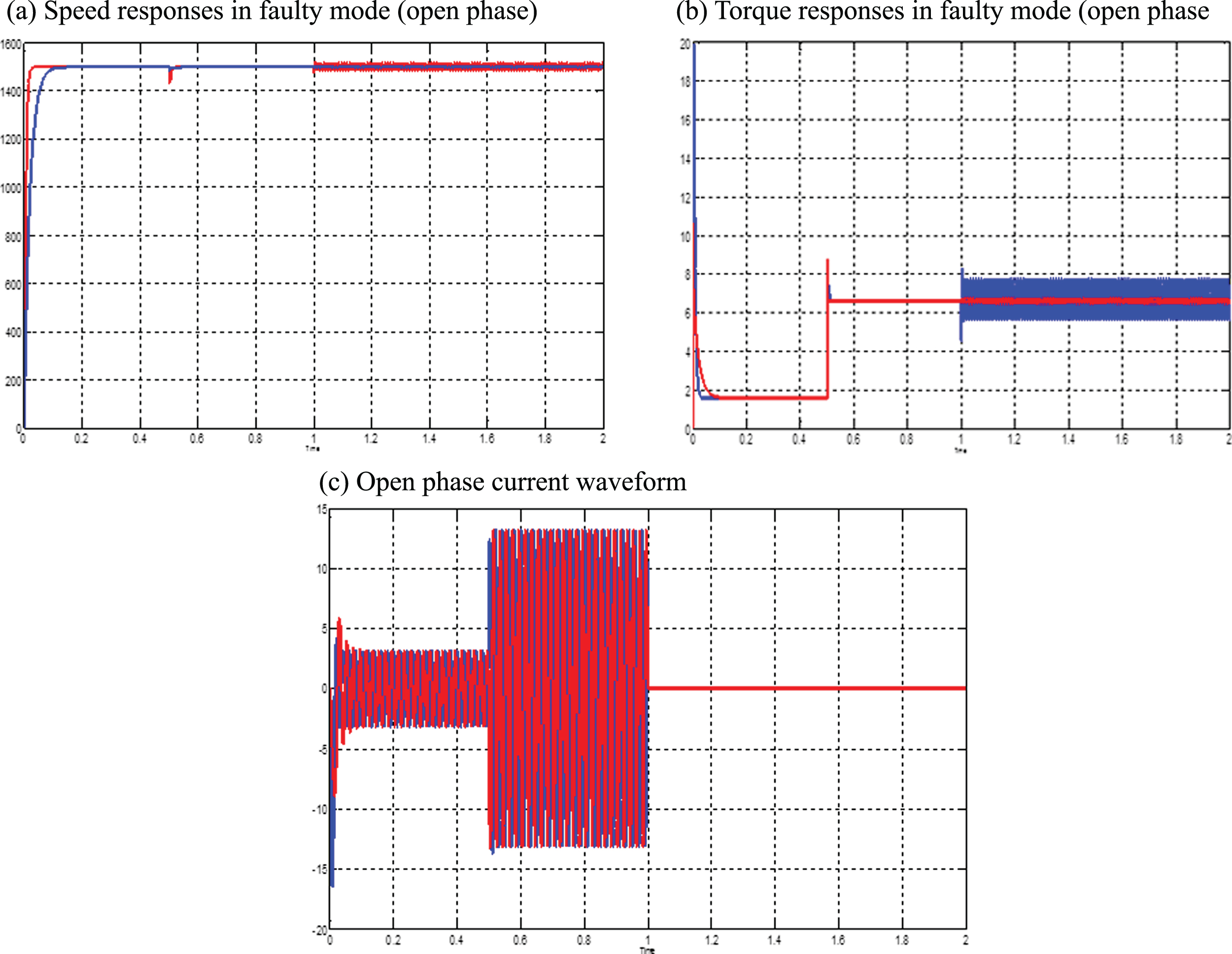
According to Fig. 6(a), one can notice well that with the classical regulator, speed converges more quickly; on the other hand, the effect of the disturbance due to the introduction of load at the moment 0.5 s is much weaker. At the moment 1 s, a phase is disconnected, speed remains practically unchanged with the fuzzy regulator, and it is not the case with the classical regulator.
The electromagnetic torque is given on Fig. 6(b), it is remarkable that the fuzzy regulator made it possible to reduce torque ripple rate from 31.74% (IP regulator) to 5.29% (fuzzy regulator) with the same average torque. Moreover, with the fuzzy regulator, the inrush current is about half of that using an IP regulator.
Using the same previous rules in fuzzy regulator and the same 5Nm load at 0.5 s, we simulate the FOC of the FPSM under faulty mode, two phases are initially open. Simulation results are shown in Fig. 7(a) (speed) and 7(b) (torque) for two adjacent phases and Fig. 8(a) and 8(b) for two non-adjacent phases. (a) Speed responses in faulty mode (two adjacent open phases. (b) Torque response in faulty mode (two adjacent open phases). (a) Speed response in faulty mode (two non-adjacent open phases). (b) Torque response in faulty mode (two adjacent open phases).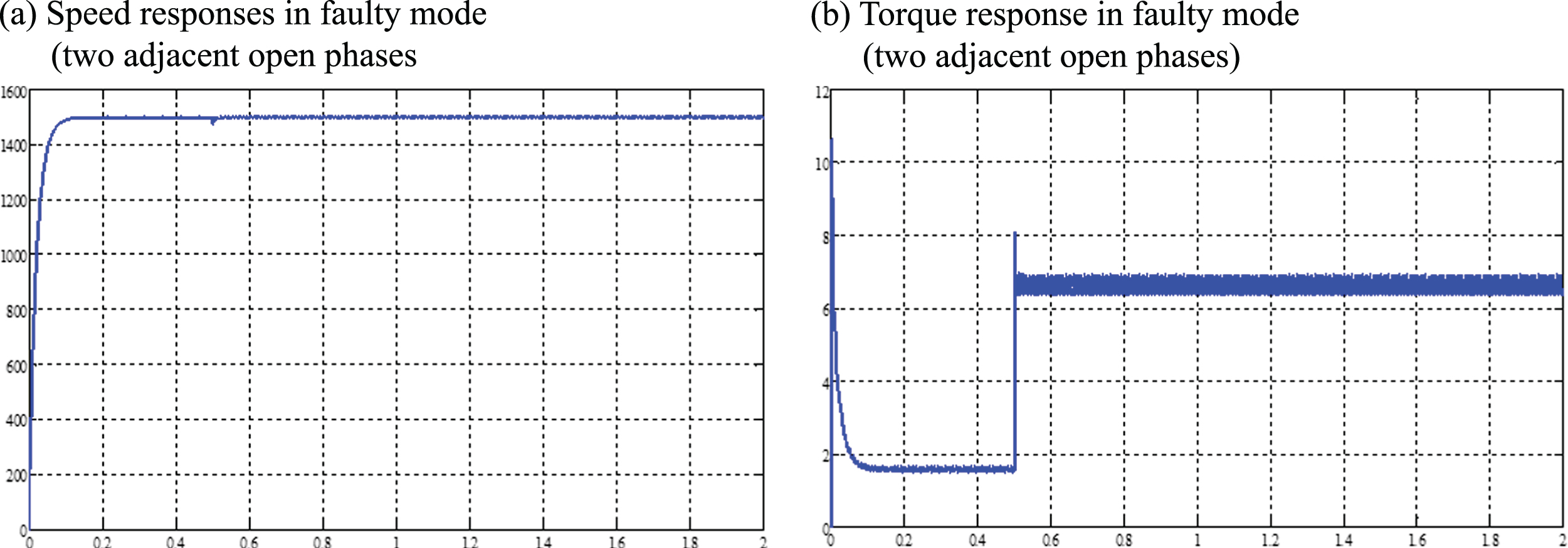
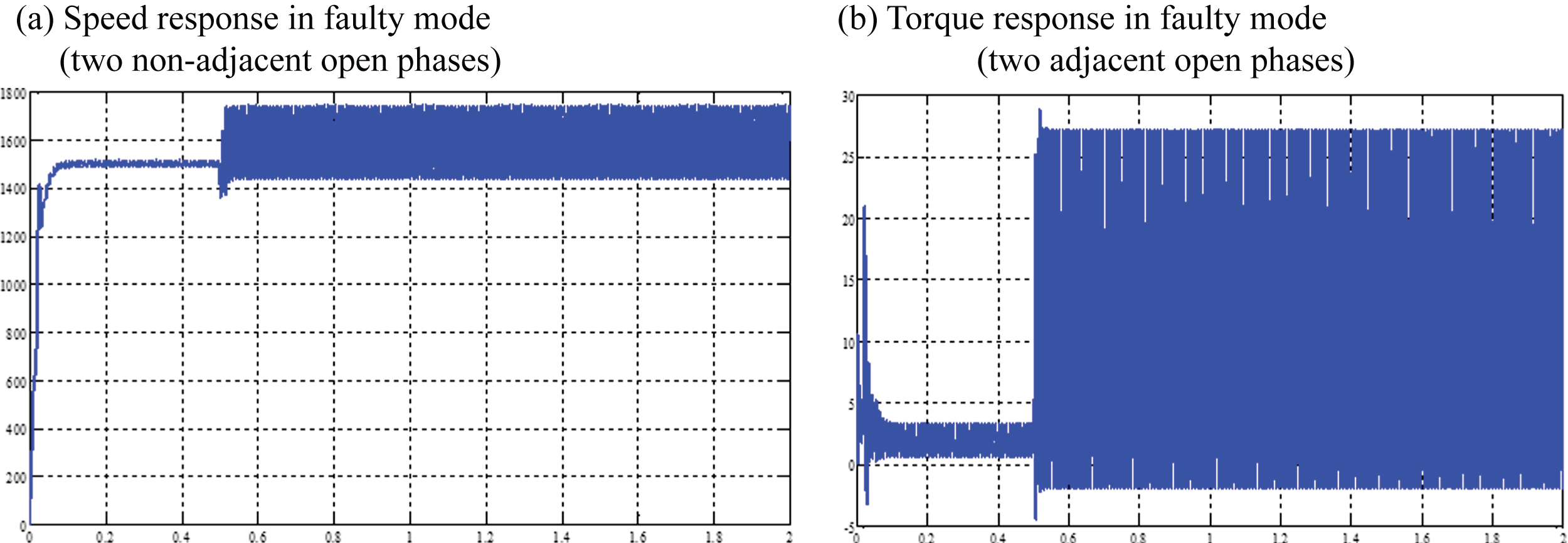
With two non-adjacent open phases, FLR is unable to perform speed and torque control.
In this paper, the behavior of five phase synchronous machine controlled with field oriented control using fuzzy regulator is presented. Performances are compared with IP regulator. A simple structure of fuzzy logic regulator has been proposed.
This structure has been interpreted from the dynamic behavior of five-phase synchronous machine. The effectiveness of the fuzzy logic controller has been established by simulation of faulty operating conditions. Simulation results were justified when simulating an opening phase during operation of the machine and the operation of the simulation of the machine with two phases initially open. Fuzzy logic allows well to ensure a tolerant control the opening of two adjacent phases minimizing the pulsating torque but is unacceptable for two non-adjacent phases.
Footnotes
Acknowledgments
This publication was made possible by internal grant # [QUCP-CENG-17/18-2] from the Qatar University. The statements made herein are solely the responsibility of the authors.