
Abstract
This paper presents a practical implementation of an interval type-2 fuzzy logic controller for two stages photovoltaic system consisting of DC- DC boost converter and three-phase inverter. The power converter circuits are nonlinear and have uncertainties. These uncertainties cause noise and delay in the response of power systems. A photovoltaic system has also uncertainties caused by itself. The change in temperature and irradiation cause the change in parameters of photovoltaic systems. Conventional controllers and type-1 fuzzy controllers can’t overcome uncertainties. The main objective of this study is to show the superiority of interval type-2 fuzzy logic controller to overcome the uncertainties. Interval type-2 fuzzy logic controller algorithm was developed for DC- DC boost converter and three-phase space vector modulated inverter. To make comparison, the system was controlled by a type-1 and an interval type-2 fuzzy controller respectively. Simulation studies and real time application were performed. Settling time, overshoot and ripple voltage were investigated for the boost converter. Current and voltage harmonic analysis, frequency and phase angle data were analyzed for three-phase inverter. According to the simulation results and the practical results, interval type-2 fuzzy logic controller offered better solution for the whole system.
Introduction
Emission of harmful gases released to the environment on the atmosphere continues due to using consumable fossil fuels for energy production. Using solar energy as an alternative energy source is very useful for the economy in the countries that have high solar energy potential.
The International Energy Agency defines PV system in two categories as standalone and grid-connected PV systems. According to IEEE-929 (IEEE Recommended Practice for Utility Interface of Residential and Intermediate Photovoltaic Systems), current total harmonic distortion (THD) must be lower than 5%, frequency variation must be in limit of 1 Hz, voltage variation must be in limit of 85% and 110% and power factor must be at least 0.9 [26].
Obtaining an adequate and constant voltage for the inverter input and setting the PV panel voltage to a required voltage becomes possible with two stages PV design. Satapathy et al. [22], Nanou et al. [27], Xiao et al. [5] and Cai et al. [6] designed two stages PV system and they powered three-phase loads and DC loads. Alternatively Abramovitz et al. [1], Tang et al. [34] and Armstrong et al. [14] designed single stage PV system. Single stage and two stages PV design were compared according to the power loss with five different scenarios by Wu et al. in [30]. The total power loss in single stage design was found as 4.34% and it was found in two stages design as 4.5%. The total power losses are nearly equal as seen from the results. In this study, in spite of the surplus loss less than per ten thousand sixteen and because of working DC loads with the same system and flexible PV panel installation, two stages PV system design was performed.
Uncertainty affects decision-making and appears in a number of different forms. Uncertainty is a result of some information deficiency, which may be incomplete, imprecise, fragmentary, not fully reliable, vague, contradictory, or deficient in some other way [20]. Attivissimo and the others [4] evaluated the uncertainty on the series and shunt resistances for PV cell model obtained from the data of manufacturer. Since the electrical characteristics of the PV cells vary with solar irradiance and temperature, the need to reproduce the environmental conditions is a very difficult challenge and the uncertainty occurs. Photovoltaic systems have uncertainties because the measurements are done at standard test condition but the system installation is done in different conditions. The installation location of PV modules causes uncertainties too.
Power circuits used in PV systems are non-linear structure and contain uncertainties. The sources of uncertainties in power circuits are topology, parameters for instance temperature dependent elements choice, controllability, location of elements and generators, load variation, various faults for instance frequency, impedance, distribution, duration faults, measurement errors, time delays, noise and signal loss. All these problems and uncertainties direct people to research new control algorithms to supply high accuracy, easy programmable, cheap and fast design. A higher degree of uncertainty in control applications means that there is noise in the control process mainly due to a changing environment for the plant or when information is transmitted (like in the feedback process in the control loop) [19].
Various fuzzy sets along with their extensions may be used to model and handle uncertainties. Hesitant fuzzy sets, Atanassov’s intuitionistic fuzzy sets, fuzzy multisets, and type 2 fuzzy sets are general fuzzy sets with extensions. Hesitant fuzzy sets are used when an element has several membership value and used for especially quantifying linguistic evaluation information [9, 31], scientific evaluation and prioritization approach to solve group decision-making problems [32, 36]. Atanassov’s intuitionistic fuzzy sets are formed by adding the degree of non-membership to fuzzy set [11] and may be used for pattern recognition and intuitionistic fuzzy multi-attribute decision-making [2]. In fuzzy multisets, the membership can be partial (instead of Boolean as for standard multisets) [24]. The concept of fuzzy multisets was used widely in automata theory [25]. Type 2 fuzzy sets are a generalization of the former where the membership of a given element is defined as a fuzzy set [31].
Conventional FLC (hereafter it will be called as type-1 FLC) isn’t so effective for the systems containing uncertainties so a new fuzzy set concept was introduced by Zadeh [13] as called type-2 fuzzy set. Uncertainties in the systems can be defined better with type-2 fuzzy sets.
Atacak and Bay [8] developed a model for type-2 controlled buck, boost converters separately, and realized a simulation study. Uncertainties also occur in three-phase inverters. Lin and Chen [33] used self-adaptive interval type-2 neural fuzzy network to control permanent magnet linear synchronous motor (PMLSM) as load.
In this study, design and implementation of DC- DC boost converter that increases the voltage from the solar panels to the appropriate DC level for the inverter input and three-phase space vector modulated (SVM) inverter were performed. Interval type-2 fuzzy logic controller (IT2FLC) was developed as a control algorithm for the voltage of DC-DC converter and the currents of three-phase inverter. The system was also controlled using type-1 FLC to show the superiority of the proposed IT2FLC algorithm. Previously, the system was controlled as simulation and then real time application was performed. MATLAB, Simulink and Simpower tools were used for simulation studies. The system was controlled with TMS320F28335 DSP on eZdsp F28335 DSP module for real time application. The developed algorithms which are embedded in Simulink blocks were converted to machine language for the target DSP by using Real Time Workshop (RTW), Link for Code Composer Studio Development Tools and Embedded Target for TIC2000 Support. The studies on power converter control with interval type-2 fuzzy logic controller are generally simulations but in this study, the superiority of interval type-2 fuzzy was showed in practical application of the two stages power converter. Comparative results were evaluated for DC-DC converter and three-phase inverter separately. The results showed that interval type-2 fuzzy logic controller handled the uncertainties better than type-1 fuzzy logic controller.
Type-1 and interval type-2 FLC
Fuzzy sets were invented by Zadeh in [12]. In fuzzy set (this will be called as type-1 fuzzy set), the membership degree of the value is a value between 0 and 1.
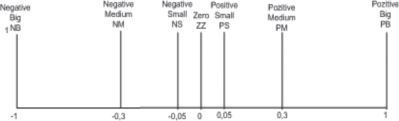
The inputs for type-1 FLC (T1FLC) for controlling the output voltage of DC-DC converter are error and change in error as illustrated in Equations (1) and (2) respectively. The Membership Functions (MFs) for error and change in error are labeled as Negative Big (NB), Negative Medium (NM), Zero (ZE), Positive Medium (PM) and Positive Big (PB) as seen from Figs. 1 and 2. Triangular five MFs are selected to lower the computational time and memory size for the DSP. The output of T1FLC is the change in the duty cycle of PWM produced from DSP and the MFs for it can be seen from Fig. 3. The duty cycle sent to the switching element (IGBT) can be calculated with Equation (3). The controlling signal of PWM duty ratio for the converter is selected from the rule base that can be seen from Table 1. The rule base is 5×5 Mac-Vicar Whelan rule base. The inference method is MAX-MIN method.
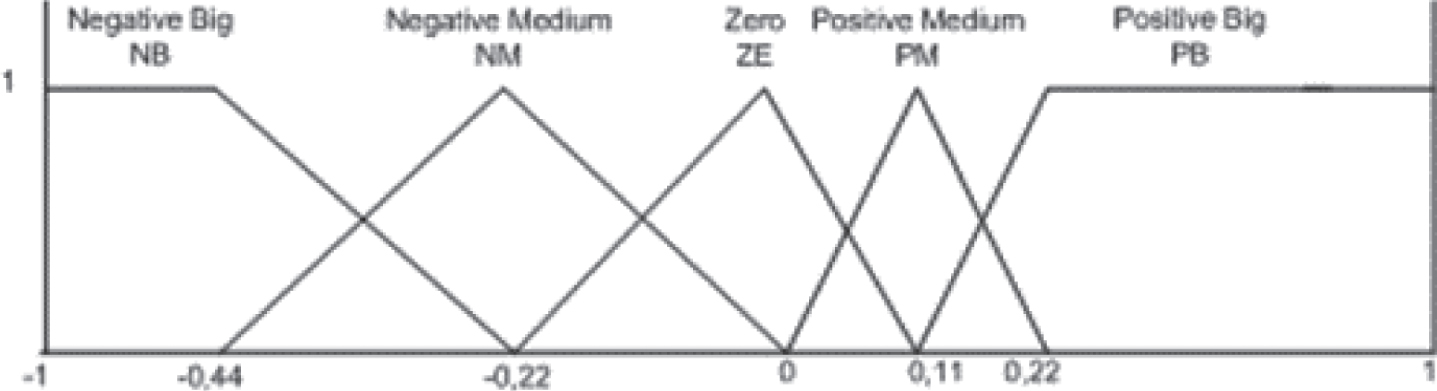
Type-1 MFs of error for DC-DC converter output voltage regulation.
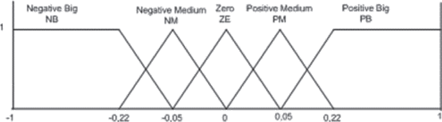
Type-1 MFs of change in error for DC-DC converter output voltage regulation.

Type-1 change in duty cycle MFs for PWM output.
Rule base for T1FLC and IT2FLC in DC-DC converter
Three-phase currents are converted to i
α
and i
β
currents on stationary frame with Clarke transform. These currents are converted to i
d
and i
q
currents on the rotational frame rotating with θ angle synchronously. Control algorithms are used for d and q axes on rotating coordinate frame. In this study, the currents on d and q axes are controlled with T1FLC and IT2FLC respectively. Three-phase inverter control was implemented with two controllers, first one is for regulating d axis current and the second one is for regulating q axes current. The input variables for regulating d and q axes current in FLCs (T1FLC and IT2FLC) are error (e (k)) and change in error (de (k)) and can be calculated as (4) and (5).
As the reference current for d axes is determined from the first stage, the reference current for q axes is zero for power factor. FLC output is calculated as
The control signals obtained from these FLC algorithms are the change in the voltages on the stationary axes. du(k) used for d axes is the change in V α and du(k) used for q axes is the change in V β .
These voltages are the reference voltages for Space Vector Modulation (SVM). The duty cycles of the switches in the inverter are determined according to the SVM.
The input variables MFs for Id and Iq are shown in Figs. 4 and 5 respectively. The output MFs of Id and Iq regulation is shown in Fig. 6. The rule base for control three-phase inverter is shown in Table 2.
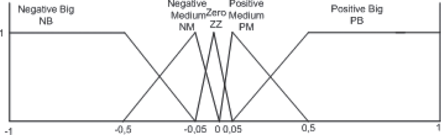
Type-1 MFs of error for Id and Iq regulation.
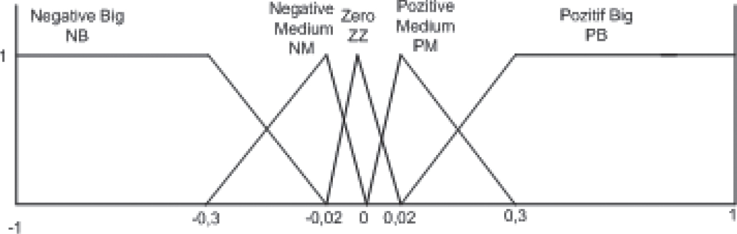
Type-1 MFs of change in error for Id and Iq regulation.
Type-1 output MFs of change in V α for Id regulation and change in V β for Iq regulation.
Rule base for Id and Iq regulations for T1FLC and IT2FLC
Type-1 fuzzy sets cannot symbolize high-level uncertainties. The limits of the sets, the number of MFs and the rule base cause uncertainties. Determining the accurate antecedent and consequent fuzzy MFs may not be possible because of these uncertainties. An expert may cause uncertainties too while forming the rule base because of different people’s different ideas on different situations. An uncertainty associated with the words may appear too. To handle these uncertainties and to make all of the process as fuzzy in the system, Zadeh proposed a new control algorithm in [13]. Type-2 fuzzy sets are effective for modeling these uncertainties. Instead of being two-dimensional, as a type-1 fuzzy set is, a type-2 fuzzy set is three dimensional. It is this additional dimension that lets uncertainty be handled within the framework of FL [10].
Interval type-2 fuzzy sets are a special kind of type-2 fuzzy sets and used in control applications due to the simplicity and the suitability for embedded processors. Interval Type-2 Fuzzy Logic Systems (IT2FLSs) outperform type-1 fuzzy logic systems while facing different uncertainties such as dynamic uncertainties, rule uncertainties, external disturbances and noises [15]. The uncertainties are determined between an interval. However, the systematic design of IT2FLS is still a challenging problem due to the difficulty in determining the parameters of the sets. To determine these parameters new optimization methods or new algorithms used with type-2 FLC may be used [28, 29].
General block diagram of type-2 FLC is shown in Fig. 7. Type-2 FLC consists of five sections: Fuzzifier, Knowledge Base, Inference Engine, Type Reducer and Defuzzifier. Fuzzifier maps a crisp point
into a type-2 fuzzy set
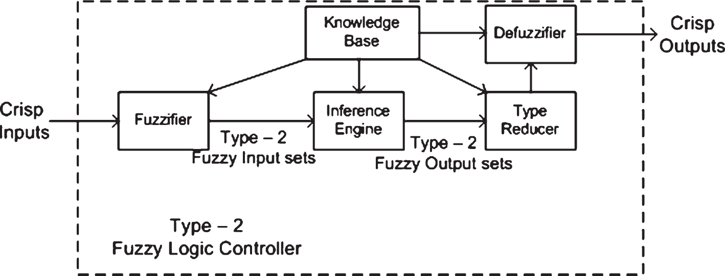
General block diagram of T2FLC.

Examples of type-2 fuzzy sets formed (a) by changing the width of a triangular MF; (b) by sliding the vertex of a triangular membership function.
Inference engine combines and computes the rules and gives a mapping from type-2 fuzzy antecedent sets to type-2 fuzzy consequent sets. The firing weights in the rule base are calculated for all fired rules. The firing weight Fi (x’) of the ith rule consists of an interval fuzzy set with a lower firing level
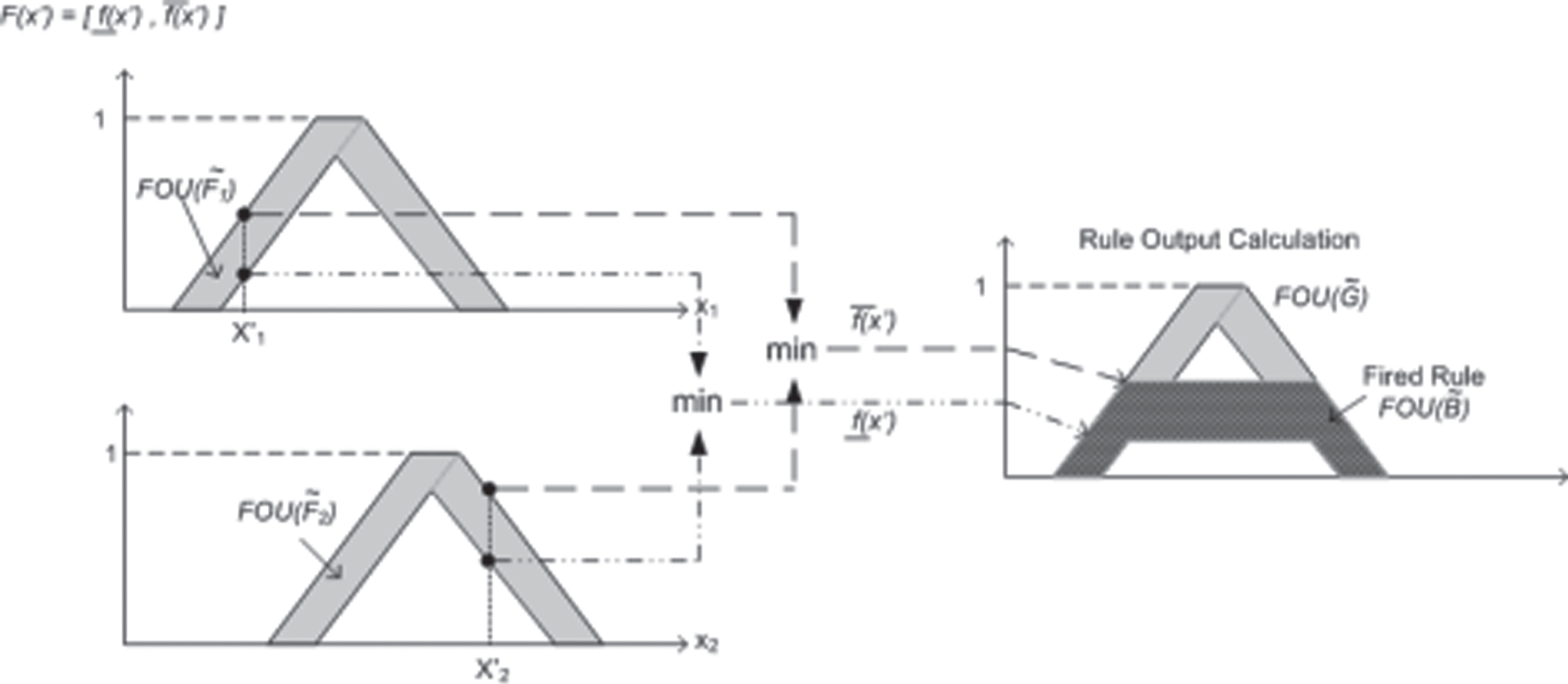
Representation of firing interval calculation using Mamdani’s min implication [16].
Type reducer transforms the interval type-2 fuzzy set output into interval type-1 fuzzy set as called type-reduced set. It provides to find the center of gravity of the IT2 fuzzy set.
The type-reduced set represent the output of the type-2 FLC as a fuzzy set rather than as a crisp number, which cannot be done with a type-1 fuzzy system [18]. Lynch et al. made a comparative study for Karnik-Mendel iterative type-reduction and Wu-Mendel Uncertainty Bounds Procedure and they found very small error within only 1% of set-point [3]. Wu-Mendel Bounds method could be found as a valid approximation for the type-reduction process, and thus as a useful and valid a means for real-time control operations.
The type-reduced set for an IT2FLC is an interval set that is determined with two end points y r (x) and y l (x) regardless of the reduction methods. The type-reduced set using the centre of sets type-reduction is expressed as
Wu and Mendel proposed to approximate the type-reduced set by its bound sets
Defuzzifier calculates the crisp output of IT2FLC by using the bounds of the type-reduced set. The crisp output obtained with Wu-Mendel Uncertainty Bound procedure is as Equation (20).
Solar energy systems have advantages such as no wastes polluting the atmosphere, minimal operation cost except for installation, noiseless study and low maintenance cost due not to containing movable parts [17]. In this study, PV panel model, DC-DC boost converter model and three-phase inverter model were implemented with MATLAB/Simulink.
The output voltage of PV sourced DC-DC converter was fixed to 620 V DC and this voltage was converted to 380 V AC with three-phase inverter. There are 30 PV panels with total maximum 5.4 kW mounted on the roof of Gazi University.
Simulation of two stages power converter
Simulation of PV sourced two stages converter was implemented with MATLAB/Simulink. The controller algorithms for the power converters were written with MATLAB codes. The Simulink model of the whole system is shown in Fig. 10.
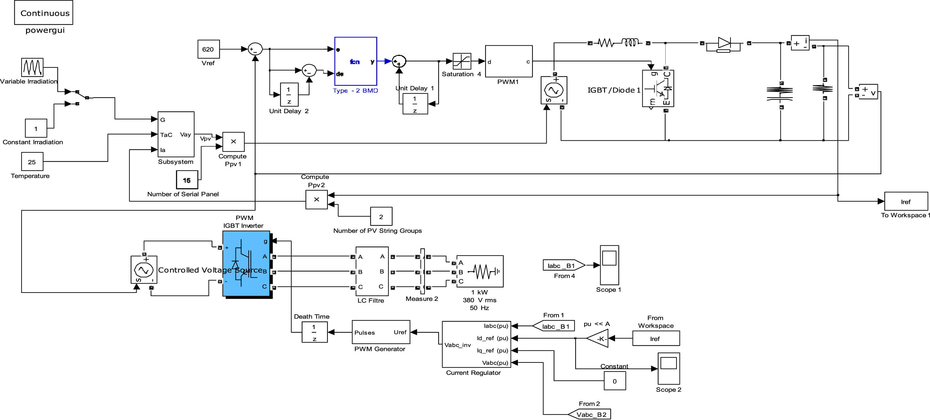
Simulation model of developed two stages converter sourced by PV panels.
The PV sourced DC-DC boost converter. was controlled with T1FLC and IT2FLC respectively to determine the most appropriate algorithm and this study was presented by Yatak and Bay in [16].
IT2FLC design for three-phase inverter
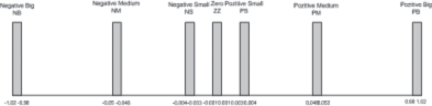
The input variables Equations (4, 5), the output variable Equation (6) and the rule base for IT2FLC in three-phase inverter (Table 2) are the same with type-1 FLC. The triangular interval type-2 MFs were used for the input variables because of easy implementation of them and so less calculation requirement. Figures 11 and 12 show these MFs for error and change in error respectively. Singleton structure was chosen for the interval type-2 MFs for the output variable and it can be seen from Fig. 13.

IT2 MFs of error for Id regulation.

IT2 MFs of change in error for Id regulation.
IT2 output MFs of change in V α for Id regulation.
Figures 14 and 15 show the interval type-2 input MFs for regulating the q axes current Iq. The output MFs for Iq regulation can be seen from Fig. 16.

IT2 MFs of error for Iq regulation.

IT2 MFs of change in error for Iq regulation.

IT2 output MFs of change in V β for Iq regulation.
Triangular interval type-2 MFs were used for the input variables because of easy implementation and so less calculation requirement. Singleton structure was chosen for the interval type-2 MFs for the output variable.
In this study Wu-Mendel Uncertainty Bounds Procedure was used for type-reduction process. Wu and Mendel [7] improved equals to determine the key points used for type reduction method. This practical solution provides type-2 FLC to be used in real time complex application.
To show the robust control property of IT2FLC for three-phase inverter, a reference signal for d axis with the variable irradiation can be seen from Fig. 17. Three-phase inverter currents in the condition of variable irradiation according to the reference current were obtained from the simulations. Figure 18(a) shows type-1 FL controlled PV system currents according to the reference current in Fig. 17. The signals during 2.5 periods were obtained to show the control effect in Fig. 18(b). Figure 19(a) and (b) show the PV system output currents and the signals during 2.5 periods controlled with IT2FLC.
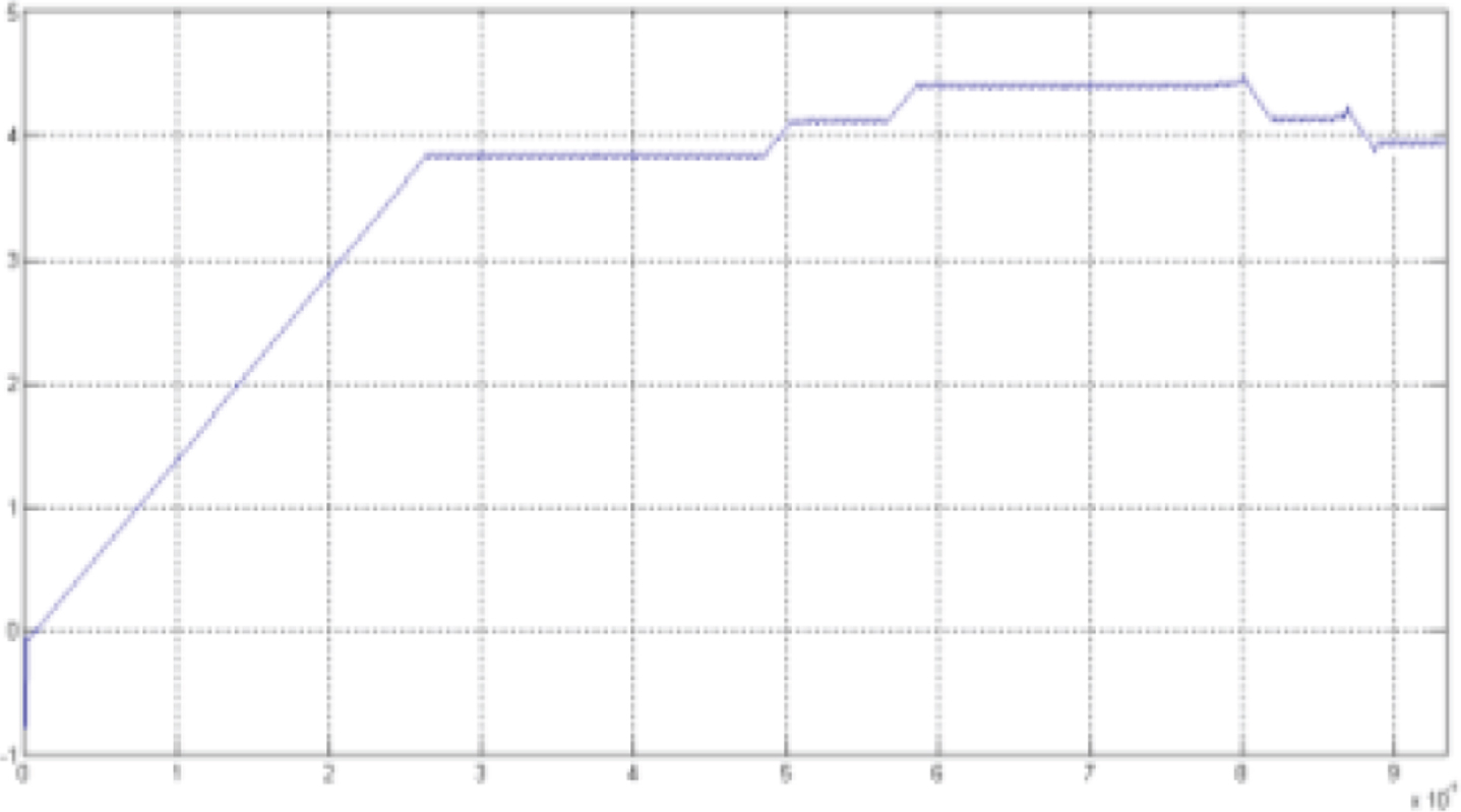
Reference current for Id in the irradiation change situation.
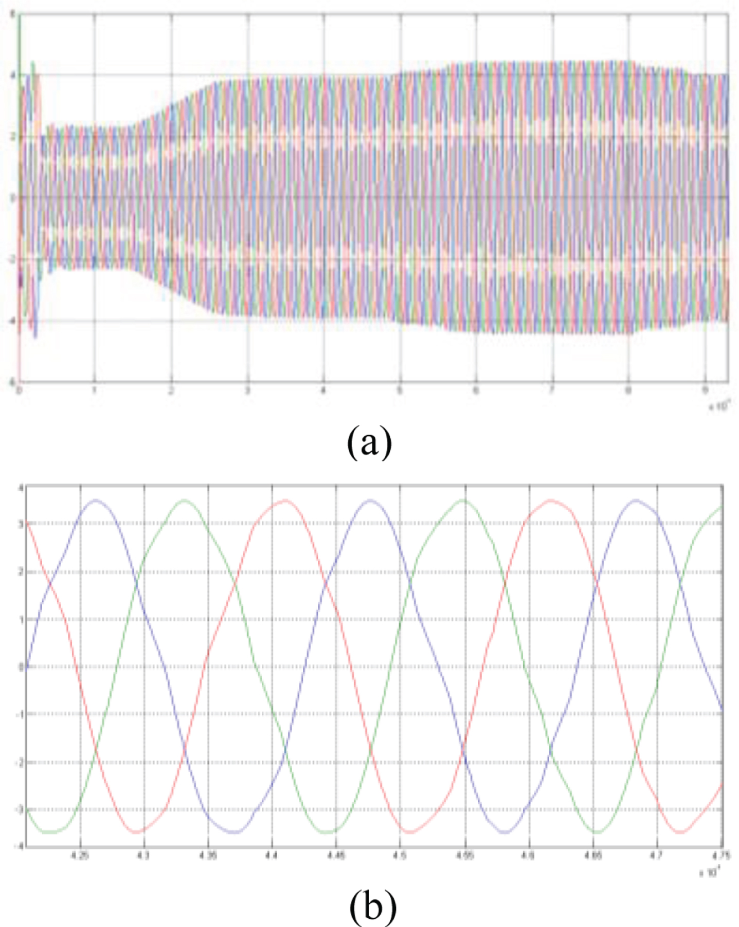
Type-1 FL controller (a) PV system output three-phase current (b) Three-phase currents during 2.5 periods.

Interval type-2 FL controller (a) PV system output three-phase current (b) Three-phase currents during 2.5 periods.
The current distortion in type-1 FLC has been removed with IT2FLC as seen from Fig. 19.
Unstable PV panel voltage was increased to 620 V with DC-DC boost converter for three-phase inverter input. Then this voltage was converted to three-phase voltage with inverter. Realized two stages power converter sourced by PV panels is shown in Fig. 20.

Schematic diagram of the realized PV sourced two stages power converter.
Hardware elements of the implemented system are PV panels (KD180GH-2P), eZdsp F28335 DSP module, irradiation sensor (CMP11) and temperature sensor on the panels (DS18B20), data acquisition circuit, current and voltage sense circuits, capacitors for PV panels, DC-DC boost converter, intelligent power module (Mitsubishi - PM150CL1A120), IPM isolation circuit, LC filter circuit. Picoscope 3423 was used as data logger and Fluke 434 was used as power quality analyzer.
eZdsp F28335 module produced by Spectrum Digital was used to control the system and it was programmed on USB port of the computer with Code Composer Studio (CCS) interface program. MATLAB/Simulink is a model-based development program when used with Target Support Package TC2 Toolbox. DSP algorithms with block diagrams are translated into machine codes for the target DSP with Real Time Workshop (RTW), Link for Code Composer Studio Development Tools and Embedded Target for TIC2000 DSP sub-software and real-time implementation and design verification can be made easily. Irradiation data obtained by CMP11 pyranometer and temperature data obtained by DS18B20 temperature sensor are transferred to the computer by designed data acquisition circuit using RS232 serial protocol.
PWM signal was isolated with 6N137 optical isolator and driven with a designed circuit consisting of VLA106-15242 converter and M57962CL-01 gate driver integrated circuits for the DC-DC converter. HCPL 4506 gate drive interface optocouplers were used to isolate the inverter PWM signals and M57140-01 hybrid IC was used for the driver supply voltage. Differential probe (Pintek DP-100) was used to separate the system GND and the measurement instrument (Picoscope 3423) and it supplies attenuation. The voltage mode controller is proposed for the control of the DC-DC boost converter output voltage. A voltage sensor LV-25/P-SP2 by LEM was to detect the output voltage of the converter. LTS25-NP current sensors were used to sense the inverter currents.
Experimental results
Performances of the proposed IT2FLC of PV sourced two stages power converter were verified by the comparison with T1FLC. T1FLC and IT2FLC algorithms MATLAB codes were written in the Embedded MATLAB function block in Simulink. The system model realized with MATLAB/Simulink was embedded to TMS320F28335 DSP with eZdsp F28335 module. and this embedded model can be seen in Fig. 21.

PV sourced two stages power converter embedded model formed with MATLAB/Simulink.
In this study, the output voltage of the DC-DC boost converter and three-phase currents of the inverter were controlled with T1FLC and IT2FLC individually and the best solutions were obtained with IT2FLC. Balanced three-phase load were used with total 1.2 kW for the experiments.
Uncertainties sourced by nonlinear structure of the power circuits, variations of the environmental conditions and the sensor readings could be modeled and included in the control algorithm with type-2 FLC so a robust control can be obtained.
The first stage of the PV system is DC-DC boost converter and the output voltage was fixed to 620 V with T1FLC and IT2FLC. The overshoot, settling time and ripple voltages were considered in the experiments. DC-DC boost converter output voltages are shown in Figs. 22 and 23 respectively. The differential voltage probe is selected as x500 attenuation and each square is 200 V for both measurements.

Output voltage of Type-1 FL controlled DC-DC boost converter.
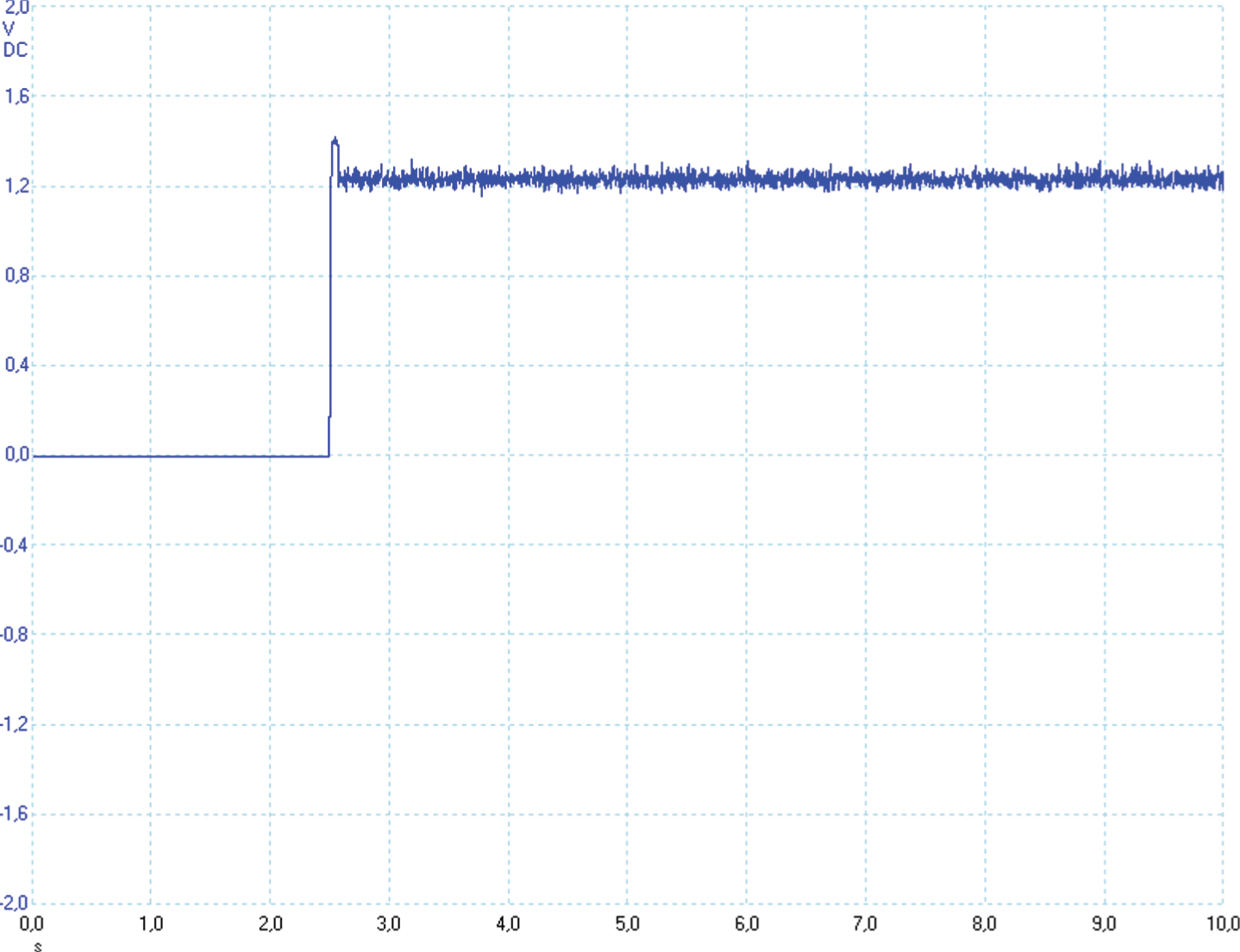
Output voltage of IT2FL controlled DC-DC boost converter.
Three-phase currents and the voltages of the inverter were measured with Picoscope 3423 and the power and harmonic data were measured with Fluke 434 power quality analyzer. Type-1 FL controlled PV system currents are shown in Fig. 24(a) and the voltages are shown in Fig. 24(b). The phase difference and the frequency were obtained too. The total harmonic distortion (THD) of a signal is mostly used to indicate the power quality of power systems. In a power system, lower THD will cause reduction in peak currents, heating, emissions, and core loss in machines [21].THD graphs for the current and for the voltages are shown in Fig. 25(a) and (b) respectively with T1FLC for the inverter.

T1FL controlled three-phase inverter (a) Output currents (current probe was selected as 10 mV/1 A) (b) Output voltages differential voltage probe is selected as x500 attenuation and each square is 200 V).

THD and power data for T1FL controlled three-phase inverter (a) THD for the output currents (b) THD for the output voltages (c) Power data.
IT2FL controlled PV system currents are shown in Fig. 26(a) and the voltages are shown in Fig. 26(b). THD graphs for current and for the voltages are shown in Fig. 27(a) and (b) respectively.

Interval type-2 FL controlled three-phase inverter (a) Output currents (current probe was selected as 10 mV/1 A) (b) Output voltages (differential voltage probe is selected as x500 attenuation and each square is 200 V).

THD and power data for IT2FL controlled three-phase inverter (a) THD for the output currents (b) THD for the output voltages (c) Power data.
Table 3 shows the results of the controllers separately for DC-DC converter and three-phase inverter summarily consisting important performance criteria.
Application results of PV system according to control algorithms
The overshoot voltage of DC-DC boost converter is 7% while controlling with T1FLC and 6.7% while controlling with IT2FLC. There is a 0.3% improvement on overshoot voltage. The settling time is measured as 0.731 ms with T1FLC and 0.073 ms with IT2FLC. The response is accelerated about 10 times with IT2FLC. The amount of maximum ripple voltage at steady state is 39.5 V with T1FLC and 42 V with IT2FLC. The most improvement of the responses on shortening the settling time could be supplied with IT2FLC for DC-DC boost converter.
Current THD, voltage THD, frequency and phase angle data were selected to evaluate the controllers. Current THD was obtained as 3.9% and THD for the output voltages was obtained as 3.9% with T1FLC. Current THD was decreased to 3.5% and voltage THD was lowered to 3.7% with IT2FLC. The 5% limit THD for the inverter current determined by IEEE 929 standard has been ensured with these two controllers.Lowering THD reduces peak currents, heating, emissions, and core loss in machines. The frequency of the signals was obtained as 49.98 Hz for two controllers and this frequency is in the limits of IEEE 929 standard (±1 Hz). The phase angles of the currents were found 118.275° out of phase each other for T1FLC and 119.95° for IT2FLC. The phase difference is more accurate with IT2FLC (120°). In spite of using resistive loads for the PV system, the power factor (pf) was obtained as 0.93 for two controllers, because of LC filter. Nevertheless, it is appropriate for IEEE 929 standard as the minimum pf must be 0.9.
As seen from the Table 3 that the results confirm the validity and applicability of the proposed system according to the well-known standard IEEE-929.
This paper presented a practical implementation of interval type-2 fuzzy logic controlled PV sourced two stages power converter. The Photovoltaic Sourced Two Stages Converter was controlled with TMS320F28335 DSP on eZdsp F28335 DSP module for real time application. Settling time, overshoot and ripple voltage have been investigated for the boost converter. Current and voltage harmonic analysis, frequency and phase angle data have been analyzed for three-phase inverter. Both the first stage, DC-DC converter, and the second stage, three-phase inverter, were controlled with IT2FLC. By this way, fast response time, low overshoot and low ripple voltages were obtained for DC-DC converter and low THD for the currents and the voltages and high power factor were obtained for three-phase inverters.
Footnotes
Acknowledgments
The authors acknowledge the Gazi University Scientific Research Foundation (under 07/2007-32), which financed the research activities.