
Abstract
In order to study the heat exchanger simulation and recovery device design of waste heat boiler of gas turbine generator set on Ocean platform, the theory of thermal cycle of gas turbine and the principle of steam turbine are introduced. The waste heat of exhaust gas of a certain type of gas turbine generator set on Ocean platform is taken as the object, to design the waste heat recovery device of this type of gas turbine generator set. According to the characteristics of the selected waste heat boiler, the mathematical model is reasonably simplified, and the steady-state simulation model of the waste heat boiler is established by using the computer simulation software, thus forming the whole model of the waste heat boiler. It is attempted to recover the waste heat from the exhaust gas of gas turbine generator set in Ocean platform by using gas-steam combined cycle power generation, which has certain reference significance for the design, application and improvement of a common gas turbine waste heat recovery device on Ocean platform. The established steady-state model simulation model and thermal efficiency calculation model have good accuracy, and have a certain auxiliary role in design calculation and performance research.
Introduction
In the case of increasing awareness of environmental protection, the state vigorously advocates waste heat utilization and calls for innovation as the driving force to carry out energy conservation and emission reduction. How to improve the utilization rate of energy and reduce the emission of exhaust gas heat has become a hot topic for many people. Gas turbines are the most widely used power machinery in the world today. About 40% of the heat generated by the fuel of gas turbines is converted into the output power of the engine. More than half of the heat is taken away by the exhaust and cooling water of the gas turbines. The thermal efficiency of single cycle gas turbines is lower, only about 30%, the turbine thermal efficiency of some micro and small gas is only 20%, and there is a lot of waste heat. Apart from gas-fired power plants and marine power plants, gas turbines are widely used in China. In the field of petroleum engineering, oil fields, gas fields and Ocean oil platforms, due to the convenience of fuel supply, as well as the advantages of volume, noise and start-up speed, gas turbine generators constitute the main power plant. The exhaust gas temperature of gas turbines is generally above 400 DEG C according to different working conditions, with less dust impurities and high smoke, so it has a high value of waste heat recovery. In domestic gas-fired power plants, gas-steam combined cycle power generation is adopted for high-power gas-fired generating units, which can increase the thermal efficiency of gas turbines to more than 52%. With the development of small and medium-sized waste heat boilers, a set of waste heat recovery system is designed for gas-fired and oil-field gas-fired generating units to improve thermal efficiency, which is of great significance in reducing energy consumption [11].
State of the art
The inlet and outlet of waste heat is a hot topic for scholars to study. Liu et al. (2016) pointed out in their study that the basic principle of the inlet and outlet of waste heat is to produce cooling water to cool the compressor inlet and improve the thermal efficiency of the gas turbine through refrigerators with gas turbine exhaust as heat source [1]. Xi et al. [2] considered that the main problem of this waste heat recovery method is that the recovery object is low-grade heat source, and the tail temperature of gas turbine is generally above 400 DEG C [2]. Liao et al. [3] proposed in the study that if this method is used to recover waste heat from gas turbine exhaust gas, the gas turbine itself can be modified into a regenerative gas turbine. The refrigerator can use low-grade tail gas after heat transfer through the heat exchanger and the air inlet of the combustion chamber, or the refrigeration device can be installed in a waste heat boiler or a heat medium boiler, and the exhaust gas of the waste heat boiler and the heat medium boiler is utilized [3]. Zhao et al. [4] pointed out in the study that the waste heat refrigeration intake mode can only be used as a supplementary means of waste heat recovery of gas turbine exhaust gas, but not the main means. The main problems faced are the stability guarantee of the equipment under variable operating conditions of gas turbine, the matching of refrigeration parameters and the development of regulation system [4]. Yang et al. (2015) pointed out that the most direct and effective waste heat recovery equipment for gas turbine exhaust gas is the waste heat boiler. Whether it is steam injection gas turbine, gas-steam combined cycle or heat conduction oil to recover waste heat from the exhaust gas, the method used is boiler heat exchange. Both steam-water boiler and heat medium boilers can efficiently and conveniently convert the heat energy of gas turbine exhaust gas into other medium heat energy or working medium heat energy, which can be used for heating or engine use [5]. Peng (2014) wrote that the waste heat boiler used to recover waste heat from gas turbine exhaust gas has its own particularity compared with other waste heat boilers. Song et al. (2014) considered that the most important point is that the flue gas side resistance of the waste heat recovery boiler should be as small as possible [6]. The excessive flue gas resistance will affect the gas turbine and reduce the efficiency of the gas turbine [7]. In addition, Zhao et al. [4] mentioned that for gas turbines with frequent start-up and shutdown or load changes, the waste heat boilers used need to have a quick start-up and shutdown function, and gas turbines with load changes, waste heat boiler load changes should be stable [8]. Qu et al. [9] and Thapa et al. [10] also believed that not all waste heat boilers can be used as the recovery devices of gas turbine exhaust heat [9, 10].
Methodology
Thermodynamic cycle theory of gas turbine
The ideal simple gas turbine cycle was proposed by Brayton in 1872, also known as the Bretton cycle. It consists of the following processes, as shown in Figs. 1 and 2.
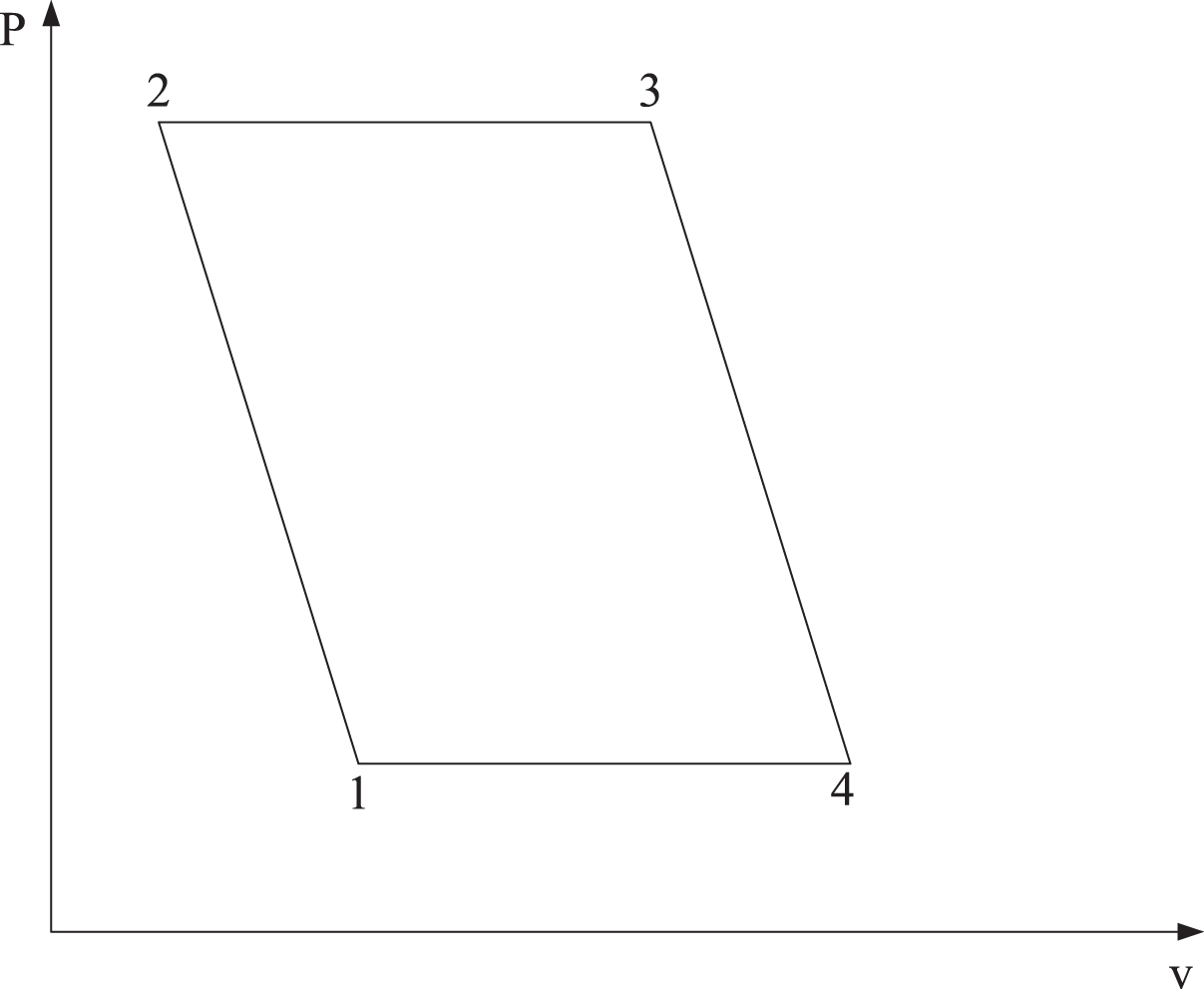
P-v (pressure capacity) diagram of an ideal simple gas turbine cycle.
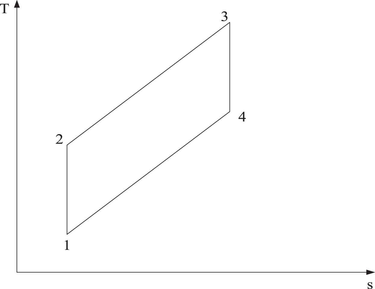
T-s (temperature threshold) diagram of ideal and simple gas turbine cycle.
First, the adiabatic compression process (the 1-2 section of the curve). In the adiabatic compression process, the heat absorption of the working medium is 0, and the whole process is completed in the compressor. The effect is that the pressure p of the air increases while the specific volume v decreases. In the pressure volume diagram, the area surrounded by the 1, 2 and p axes is the work wc of the compressor on the unit mass working medium. In the adiabatic compression process, the entropy of the working medium remains unchanged, as shown in T-s diagram, so this process can also be called isentropic compression process.
Second, the isobaric heating process (the 2-3 section of the curve). In the isobaric heating process, the mechanical work of the working medium is 0, and the whole process is completed in the combustion chamber. There is no mechanical power transfer between the working medium and the outside. The purpose is to increase the working medium temperature T while the working medium pressure p remains unchanged. In the thermo entropy diagram, the area surrounded by the 1, 2 and s axes is the heat energy q23 inhaled by the unit mass working medium during isobaric heating.
Third, the adiabatic expansion process (the 3-4 section of the curve). In the adiabatic expansion process, the working medium outputs mechanical work to the outside world. The working condition of the unit mass working medium is similar to that of the adiabatic compression process. The whole expansion process is completed in the turbine. The result is that the working medium pressure p decreases and the specific volume v decreases. In the p-v diagram, the area surrounded by the 3, 4 and p axis is the mechanical work wt done by the unit mass working medium during the whole process. In the process of adiabatic expansion, the entropy of working medium is invariable, as shown in figure T-s, so this process can also be called isentropic expansion process.
Fourth, the isothermal exothermic process (the 4-1 section of the curve). Isobaric exothermic process is the process of exothermic to the atmosphere, similar to the isobaric heating process. The working medium in this process does not output mechanical work. Therefore, the mechanical work done by the working medium is equal to 0. The pressure of the working medium is constant, and the temperature is reduced to the initial temperature state of the compressor inlet. In the thermo entropy diagram, the area surrounded by axes 4, 1 and s axis is the heat energy q41 released to the atmosphere by a unit mass of refrigerant. From the diagram T-s, it can be seen that the thermal efficiency of the gas turbine is the ratio of the area q23 surrounded by 2341 to the area surrounded by s axis. The model of gas turbine has been selected, so the research object is the heat released by gas turbine to the atmosphere, that is, how to recycle the heat released by isobaric heat release process.
During the isobaric heating process of an ideal simple gas turbine cycle, the heat absorbed by the unit mass working medium from the combustion chamber is q23:
The heat emitted into the atmosphere is q41:
In the above formula, T1 represents the inlet temperature of the compressor, Cp represents the isobaric specific heat of the working medium, and Δ represents the heating ratio of the whole thermodynamic cycle. Therefore, the cycle specific work of an ideal simple gas turbine is:
Therefore, the ideal thermal efficiency η of the ideal gas turbine is:
It can be seen from the above formula that the thermal efficiency η of an ideal simple gas turbine is only related to the supercharging ratio π, and η rises monotonously with the increase of π.
The basic thermodynamic cycle of a steam turbine power plant is the Rankine cycle. The simple steam power plant and the Rankine cycle T-s diagram are shown in Figs. 3 and 4. The 1–4 process in the figure is the work process of steam expansion in the middle of the turbine. The 2-3 process is the heat release process of the exhaust gas in the condenser under constant pressure condensation. The 3-4 process is the condensate water entering the boiler after the horizontal isotropy compression, and the 4-1 process is the heating process of condensate in the boiler.
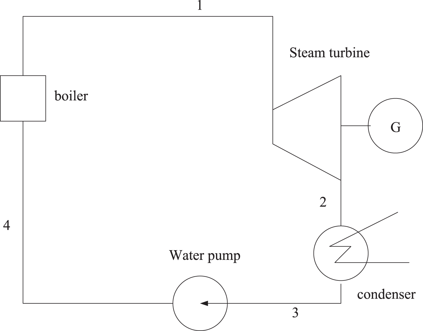
Simple steam power plant diagram.
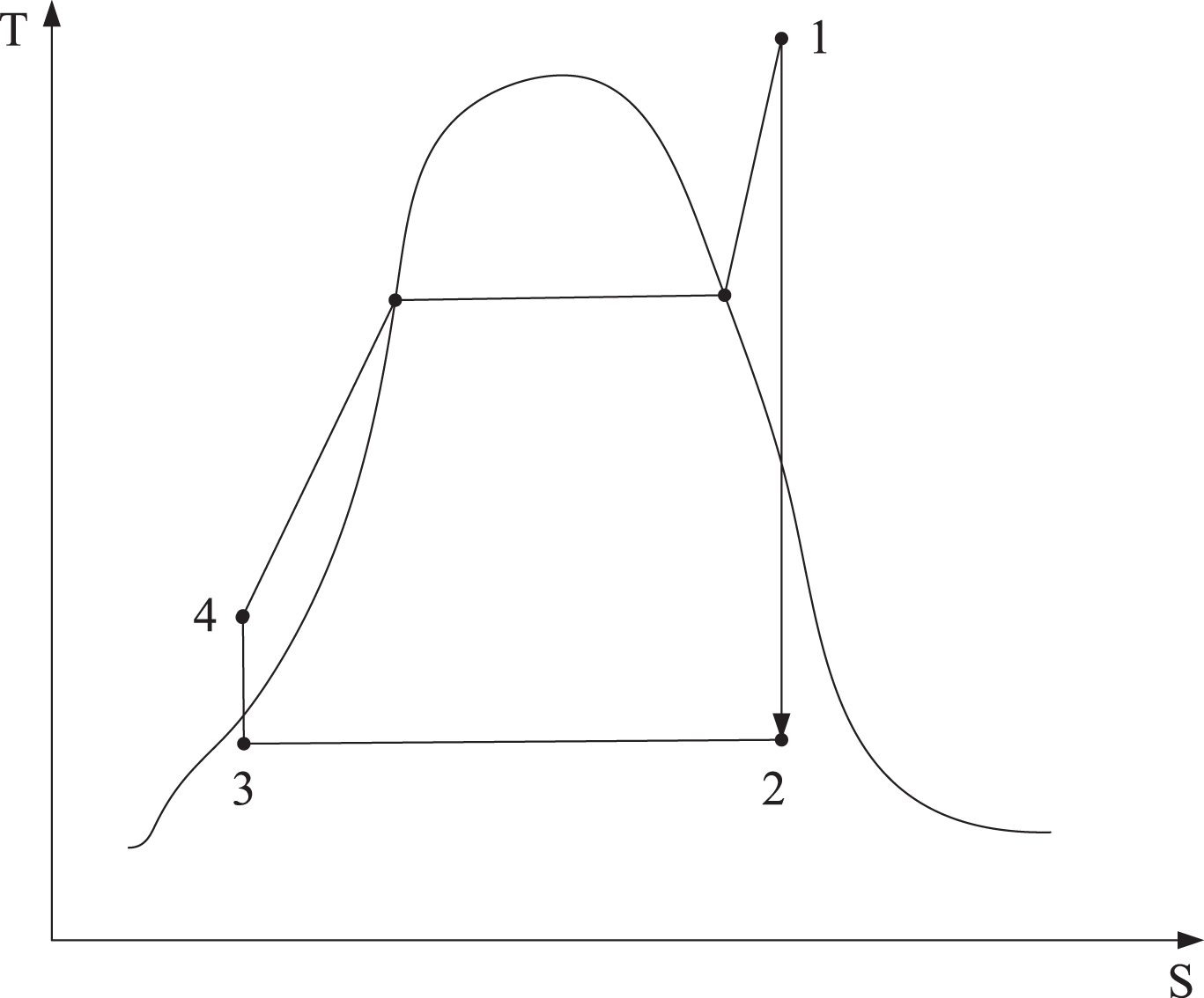
Rankine cycle diagram of simple steam power plant.
In the selection process of gas-steam combined cycle, if the waste heat boiler is given, the steam turbine should be selected according to the steam production parameters of the waste heat boiler, and its inlet parameters should match the steam production parameters of the waste heat boiler. Conversely, if the steam turbine is given, the waste heat boiler should be selected according to the demand for gas consumption in the design of the gas-steam combined cycle. If a combined cycle heat recovery unit is designed, because the type of gas turbine cannot be changed, then the exhaust gas parameters of the gas turbine generator set are given. If the reverse selection is adopted, the matching of the two groups of parameters, namely the flue gas parameters of the gas turbine and the steam inlet parameters of the steam turbine, will be considered in the selection of the waste heat boiler. This obviously increases the difficulty of selection, so the reverse selection is not reasonable. Therefore, the waste heat boiler to steam turbine type selection is used, and according to the above selected heat boiler, the turbine model is determined.
Simulation results of waste heat boiler and system heat efficiency
Firstly, the accuracy of the model simulation is verified. The gas turbine exhaust gas parameters under full load at 15 DEG C are selected as input data, and the waste heat boiler model is input. After the system is stable, the output parameters of each node and the final super-heater steam parameters are obtained, and compared with the boiler design parameters to determine the reliability of the established model applied to simulation.
The comparison between node design parameters and simulation results
The comparison between node design parameters and simulation results
The comparison between the node parameters and the simulation results show that the simulation results of the model are close to the manufacturer’s data in the stable state interval of 500 seconds. The simulation model established is accurate and can meet the requirements of steady-state simulation.
The output steam temperature of the waste heat boiler under different operating conditions of the gas turbine is compared with the atmospheric temperature curve. As shown in Fig. 5, the abscissa is the atmospheric temperature (DEEG C) and the ordinate is the superheated steam temperature (DEEG C). It can be seen from the figure that with the increase of gas turbine load, the temperature and flow of turbine exhaust gas increase, the heat of exhaust gas into waste heat boiler increases, the temperature of superheated steam produced by waste heat boiler rises, and the change of steam temperature decreases.
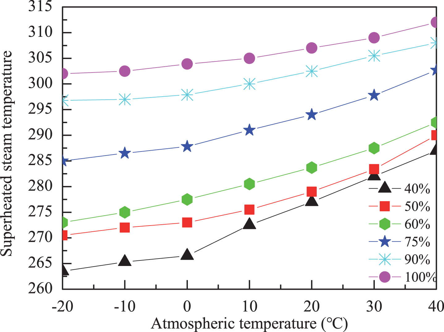
Comparison of steam temperature and atmospheric temperature variation of gas turbines under different loads.
The 1105WH00-01 waste heat boiler is equipped with a surface-type desuperheater. The superheated steam is output from the super-heater and the superheated steam is reduced by the surface-type desuperheater. The superheated steam with excessive temperature is controlled at the rated output temperature of 280 DEG C, and then the heat supply or work is output. When the super-heater output steam temperature is below 280 DEGE C, the surface-type desuperheater may lower it to a lower temperature. From the selection of steam turbine, it is known that when the inlet temperature of steam turbine is too low, the blade of steam turbine will be corroded. According to the curves of the superheated steam temperature changing with the atmospheric temperature obtained from the simulation results, it can be seen that the super-heater output steam temperature will be lower than 280 DEG C when the load and atmospheric temperature are below 10 DEG C. Considering the frequent variation of atmospheric temperature and the error of simulation results, in order to ensure the stability of waste heat recovery unit and the service life of steam turbine, the waste heat recovery unit should be closed under 75% load condition of gas turbine.
A waste heat recovery device for a typical gas turbine of a single Ocean oil platform is designed. The ocean environment is bad, and the atmospheric temperature varies greatly. In order to ensure reliability and flexibility, two to four gas turbine generators are generally used on Ocean oil platforms in a multi-purpose standby mode, which can meet the needs of the platform. A standby motor is set up to share the total burden as a means of maintenance or rotation. The gas turbine generator set is arranged on the upper deck, and each gas turbine generator set is equipped with a waste heat recovery device. The main fuel of gas turbine generator set is natural gas, the reserve fuel is diesel oil, and the power is about 12MW. Because the turbine generator set of Ocean oil platform uses non-single fuel, the refitting of steam reinjection, residual heat refrigeration intake and inner water heating intake is not feasible.
At present, gas-steam combined cycle has been used in natural gas power plants in China. With the development of small and medium-sized waste heat boilers, for many gas turbines used on land, due to no spatial limitations, a lot of gas turbines that the exhaust gas products meet the requirements can recover heat energy from tail gas by gas-steam combined cycle. On the Ocean platform, it is necessary to consider the factors of land occupation. If a set of waste heat recovery device of gas-steam combined cycle power generation can be designed within the allowable scope to realize grid-connected power generation, it is not only of great significance to energy conservation and emission reduction, but also has its special advantages in flexibility and use effect. Therefore, in the selection of the scheme, it is decided to use gas-steam combined cycle power generation to recover the waste heat from the exhaust gas of a certain type of gas turbine on Ocean oil platform. The key equipment is gas turbine, waste heat boiler, drum, turbine generator, condenser and water storage tank.
Figure 6 is a flow chart of the key equipment of the designed waste heat recovery unit on Ocean platform. The scheme includes waste heat recovery system and steam-water system. In the waste heat recovery system, the exhaust gas of the gas turbine generator unit is discharged directly through the flue to the waste heat boiler, through the super-heater, evaporator, economizer and feed-water preheater in the boiler, and the steam and water are heated in turn, and then discharged into the atmosphere by the smoke garden. In addition, a blower is installed to purge the boiler inside when it stops. In the steam-water system, the water in the deaerator enters the economizer through the feed-water pump for heating, and then enters the drum. The water heated by the economizer enters the evaporator again from the lower part of the drum. The steam in the drum is heated and evaporated to produce steam, and then enters the drum again. The steam in the drum enters the super-heater from the top of the drum and produces superheated steam to supply the steam turbine for working and driving the generator to generate electricity, and part of the superheated steam is supplied to the deaerator to supply the water tank and deoxidize the condensed water of the steam turbine.
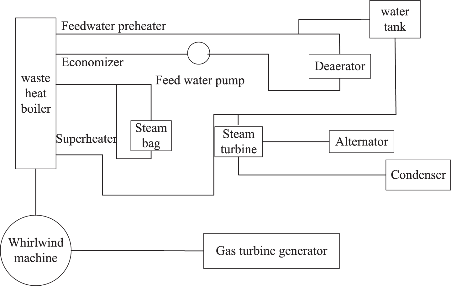
Flow chart of key equipment for waste heat recovery unit of gas turbine generator set on ocean platform.
With the increasing energy consumption and the shortage of energy demand, the state vigorously advocates energy conservation and emission reduction. According to the deficiency of user feedback in the waste heat recovery system of gas turbine exhaust gas from Ocean platforms, a gas-steam combined cycle is proposed to design a waste heat recovery unit for a gas turbine commonly used in an Ocean platform. The selection of key equipment in waste heat recovery unit is discussed, and the selection principle is discussed according to the actual use of gas turbine generator set. 1105WH00-01 single pressure natural circulation waste heat boiler and N4-1.3 condensing steam turbine generator set are selected by matching import and export parameters. At the same time, computer simulation is carried out for waste heat boiler of the core equipment of the waste heat recovery unit. According to the characteristics of the selected waste heat boiler and the purpose of steady-state simulation, the dynamic simulation model is simplified. The overall model of the waste heat boiler is established by using MATLAB/Simulink software and the accuracy of the model is verified by the design parameters. The model can be used to analyze the steady-state performance of the waste heat boiler and output the steam parameters of waste heat boiler which varies with the inlet parameters of flue gas. Using the exhaust gas parameters of the gas turbine under all operating conditions, the corresponding output steam parameters are obtained through the simulation model. The parameters are input into MATLAB to study the curve of output steam parameters of the waste heat boiler varying with the operating conditions of the gas turbine, so as to determine the application range of the designed waste heat recovery device to the target gas turbine under all operating conditions. The results show that the waste heat recovery device can meet the thermal energy recovery task of gas turbine generator exhaust gas on Ocean platform, and can increase the power output from 2800kW to 4000kW.
Footnotes
Acknowledgments
The authors acknowledge the National Natural Science Foundation of China (Grant: 111578109), the National Natural Science Foundation of China (Grant: 11111121005).