
Abstract
Intelligent vehicle technology has become a research hot issue in recent ten years, the reason is that intelligent vehicles can not only be used as a flexible weapon platform in the military. And in life, it is also a system that provides convenience and security for people. For example, driverless cars and advanced driver assistance systems (ADAS). Information processing is the key to the degree of intelligence, and the detection and recognition of traffic safety information based on monocular vision is the core of information processing, it’s also the bottleneck problem. Because of the complexity and diversity of the environment have brought great challenges to this problem. In this paper, the existing lane detection methods in structured and semi-structured roads do not specifically consider the problem of weak line detection, two models are proposed. Fuzzy LDA enhancement model is used to enhance the contrast of lane area, another brightness contrast saliency model can be used for robust Lane extraction. Then, two models are applied to lane detection, a two-stage lane detection method is proposed and a blind area vehicle detection method is designed. Firstly, the vehicle area is roughly extracted based on road gray statistics, and then the typical vehicle features are screened finely. Finally, the extracted features and SVM classifiers are used to confirm the candidate regions. Experiments show that: The proposed method can detect the vehicle in the blind area very well and is insensitive to the shape distortion and size change of the vehicle.
Keywords
Introduction
The birth of the car has greatly facilitated human life, but it has brought many problems. Among them, traffic safety has become one of the hotspots of common concern in the world [1]. According to statistics, for every 1% increase in national income, motor vehicle ownership will increase by 1.02% to 1.95%, and when per capita national income reaches 1,000 to 2,000 US dollars, the growth of car ownership will reach a peak. By 2018, China’s car ownership has reached 163 million, second only to the United States, and the car compound growth rate reached 14.9% [2–4]. The huge automobile market scale not only brings a heavy burden to the transportation infrastructure, but also brings serious safety hazards to life travel. China has ranked first in the world in traffic accident deaths for 10 consecutive years [5, 6]. According to statistics from the traffic control department, there were 204,196 traffic accidents in 2017 alone, causing 59,997 deaths. According to the statistics of the health department, the number of casualties reached 166,906, accounting for 20% of the global death toll [7–10].
To solve the traffic safety problem, the industrialized countries headed by the United States and Japan are considering the use of modern technology to improve traffic conditions, and put forward the concept of the intelligent transportation system for “safety, efficiency improvement, environmental improvement and energy conservation” [11]. The intelligent transportation system is a large-scale, all-round, real-time, accurate, efficient and advanced system that integrates advanced information technology, data communication technology and computer technology into the entire traffic management system and vehicles. Transportation and management systems [12–15]. Intelligent vehicle is an important part of intelligent transportation system. It is a comprehensive vehicle system integrating environmental information perception, intelligent planning decision-making, multi-level assisted driving and other functions. It uses computer, modern sensing, information fusion, Technologies such as communication, artificial intelligence, and automatic control are typical high-tech complexes [16–20]. The main functions of intelligent vehicles include intelligent driving systems, life service systems, safety protection systems, position service systems, etc., to improve driving safety performance, improve road traffic capacity, reduce driving intensity and improve comfort. Semi-autonomous and even unmanned vehicles are the main research targets of current smart vehicles. To achieve this goal, the intelligent vehicle detection and identification technology based on monocular vision has become the focus of this paper.
This paper briefly introduces the research background and research significance of intelligent vehicle technology, then discusses the development history of smart vehicle technology and the status quo at home and abroad, and introduces the main research directions and difficulties of intelligent vehicles in the field of driving safety, and then targets road detection, The key technologies of several intelligent vehicles such as lane line detection and vehicle detection are systematically summarized in terms of method. In the aspect of lane line detection based on target reluctance and visual saliency model, this paper first introduces the target enhancement model based on fuzzy LDA, and proposes a visual saliency model based on the model; then, using the target reluctance and visual saliency model, Aiming at the problem of missed detection of broken lines and weak lines under complicated conditions on expressways and urban roads, the lane lines are extracted by using the structural characteristics of lane lines. On this basis, the selection of lane lines and road samples is carried out. The contrast of the lane line is significantly improved, effectively highlighting the weak line on the road; finally, the inverse spatial transformation is used to further verify the spatial positional relationship between the candidate lane lines, and the dotted line of the missing detection is finally determined for different scenes and different weathers. The weak line road image was tested and analyzed.
Detection and recognition method of monocular vision traffic safety information
Intelligent transportation system
Intelligent Transportation System (ITS) is a systematic, real-time, accurate, interactive and extensive traffic management system that is integrated with modern high-tech in the transportation system. It is the development trend of global road traffic. The core idea of ITS is to use information technology intelligent management scheme to manage transportation, make all traffic elements closely cooperate, and share traffic information resources, to improve traffic management capability, optimize road use efficiency, enhance traffic safety, improve service quality, and alleviate traffic congestion, reduce energy consumption, and reduce environmental pollution. ITS is a complex and comprehensive system that requires the integration of intelligent technology and transportation technology. In this system, the intelligent recognition of images is very demanding. To a certain extent, the intelligent recognition of images determines the operational ability of the intelligent transportation system. Intelligent identification technology is a multidisciplinary technology that integrates not only computer communication technology, but also artificial intelligence, management, operations research and other aspects. Only by making full use of intelligent identification technology can comprehensively obtain comprehensive road traffic information, to realize the efficient and rational use of road traffic resources, and facilitate the traffic participants to grasp and use the traffic conditions in real-time to promote the modernization of traffic management. As a basic intelligence of human beings, image recognition technology is ubiquitous in people’s daily life. The rapid development of computer technology and electronic technology makes the computer hardware performance meet the real-time needs of image processing, and the highly plastic image processing algorithm ensures that image recognition technology occupies an important position in the intelligent transportation system. Of course, image recognition technology has become an important research object in the research of intelligent transportation systems. From a functional perspective, ITS consists of six subsystems involved in charging, management, vehicle control, emergency management, and rescue. The intersection of these six systems, or the processing object is the vehicle, the vehicle is the main adjustment target in the entire ITS, and the various functions of the ITS are completed around the vehicle. The processing of vehicle-related image information will be the key to solving specific problems. Therefore, this paper takes image recognition technology as the starting point, and combines the key technologies of some practical problems to be solved in ITS to study, to provide efficient and feasible solutions for practical applications.
An image is a collection of graphics and images. It is an information carrier that humans contact and contains rich content. When humans recognize an image, it usually recognizes it by identifying its characteristics. For the computer, the recognition process of the image is similar to that of human beings, and it is also necessary to find, process, and extract the features for judgment and recognition. Image recognition technology is a research direction of artificial intelligence, and image features are the premise of image recognition technology. After years of research, humans have already in-depth exploration of the image recognition technology industry, and have harvested a lot of results with practical use significance, the application of image recognition technology is more and more extensive. In ITS, it mainly provides traffic information consulting services and shared data resources for traffic participants. Therefore, the stability, reliability, security and flexibility of related services provided by ITS must be guaranteed. The key technology involved is image recognition technology. It can also be said that image recognition technology is the main reason for the successful use of ITS. The image recognition technology in ITS is mainly applied in the fields of intelligent car electronic information systems based on image recognition, traffic monitoring based on image recognition and traffic management based on image recognition. The intelligent car electronic information system based on image recognition mainly realizes the functions of vehicle external environment and internal information interaction, including vehicle adaptive navigation, obstacle detection, road identification, and fault analysis. Traffic monitoring based on image recognition mainly uses computer intelligent technology to intelligently identify the license plate of illegal vehicles through cameras or electronic eyes. The traffic supervision department collects, analyzes, tracks and analyzes traffic flow parameters on vehicles traveling on the road. Traffic management based on image recognition mainly realizes intelligent charging functions, including automobile license plate recognition and automobile appearance recognition. In the intelligent car electronic information system based on image recognition, the intelligent car electronic information system integrates computer intelligence, GPS, data communication, mechanical control, sensing and other technologies to realize automobile monitoring, positioning, anti-theft, information interaction inside and outside the vehicle, Fault and obstacle detection functions provide drivers with adaptive cruise, traffic accident forecasting, easy, safe and convenient intelligent driving services. Intelligent car electronic information systems play an important role in improving traffic conditions, improving vehicle handling performance, and achieving intelligent traffic. The parking assistance system, also known as the parking computer warning system, is one of the key technologies of automotive electronic information systems. Its main function is to help the driver to complete the driving task of parking, especially backward. The visual parking system is an integral part of the car’s auxiliary system. It mainly provides drivers with rear blind spot display, real-time intelligent trajectory prediction, and warning line warning zone. Generally, the hardware of the visual parking system consists of three modules: a digital camera, a central controller of the parking system, and an electronic display. When the system starts working, the camera first records and displays the environment around the vehicle in real-time. When the steering angle of the steering system of the car changes, the central controller obtains the corresponding data parameters through the CAN bus, and then calculates the real-time reverse trajectory of the car through a certain algorithm and displays it on the screen. Then, the central controller uses the sensor to transmit an ultrasonic signal to measure the position of the obstacle, and then displays the distance and issues a prompt signal. This can help the driver to eliminate the blind spots of vision and the unsightly sights and possible misoperations, and improve the safety of driving operations.
In the image recognition based traffic monitoring, the traffic monitoring technology based on image recognition mainly uses the digital camera installed on the traffic surface to collect and store the traffic information on the road surface in the image, and apply image processing and image recognition technology. Detecting and tracking vehicles in the image to obtain relevant traffic flow information and vehicle information violating traffic regulations, as a basis for traffic management control and legal ruling, thereby reducing traffic congestion, improving traffic environment, and preventing drivers from driving poorly. Habits, improve road use efficiency, and achieve safe traffic intelligence. To achieve the above objectives, the acquisition of vehicle identity information is the key. Target detection technology based on image recognition can extract some landmark key information from visual images with more information from real-time, fast and accurate in complex background. After analysis and processing by an intelligent computer system, it can be applied to ITS to achieve road traffic. Status, monitoring of vehicle driving status, and detection and forecast of traffic accidents. The license plate is one of the landmark information for realizing traffic monitoring. The license plate recognition technology has become one of the key technologies of the traffic monitoring system. It can complete the identification and search of the target vehicle and analyze the traffic flow to achieve reasonable optimization of traffic elements. Configuration to improve the efficiency of the use of traffic elements. In recent years, in the image management-based traffic management, advanced technologies in the fields of electronic sensing, wireless data communication, and computer vision have been increasingly applied to road traffic management, which has made the real-time nature of ITS increasingly The stronger, the higher the accuracy, the faster the recognition speed. An electronic non-stop charging system (ETC) based on image processing and image recognition technology is one of the practical applications. The core technology of ETC implementation lies in vehicle identification. Among them, vehicle identification and vehicle identification are two key technologies in this technology. Vehicle identification refers to the processing of the car image that is directionally captured by the camera through the relevant method of the intelligent computer terminal and classifies different types of cars to achieve vehicle identification of the car image input in real-time. The advantage of adopting this technology for vehicle type identification is that the data occupies a small storage space, and the connection speed between the client and the back-end database is fast. Automatic identification of the vehicle is one of the key technologies in ITS. This technology can be used not only in ETC, but also in traffic monitoring and other fields.
Intelligent parking system
In the intelligent transportation system, the intelligent car electronic information system based on image recognition uses computer intelligence, GPS, data communication, mechanical control, sensing, and other technologies to realize automobile monitoring, positioning, anti-theft, information interaction inside and outside the vehicle, faults and Barrier detection and other functions provide car drivers with adaptive cruise, traffic accident forecasting, easy, safe and convenient intelligent driving services. Among them, the intelligent parking system is one of the development and application of modern automotive electronic technology, and is also an important part of the automotive auxiliary system. Although there are many automatic parking systems, there are also some shortcomings that need to be solved. For example, the system cannot sense the distance between the cliff, the ditch, the protruding steel bars, the wooden sticks, the bamboo poles, etc., and the rearview image recorded by the camera is intuitive and true, but the precise distance cannot be obtained; the system products are complicated. Restriction, the system is required to be always active, the length of the parking space should exceed 1.5 meters of the body length, the steering wheel should not be touched when reversing, the reversing should be completed within the specified time (usually 3 minutes), the road rock of the road cannot be snow or leaves, etc. Waste coverage, etc.; the system may not recognize small traffic warning signs on the gates or vacancies in the yard. Therefore, the current automatic parking needs to further improve the function. If the above disadvantages can be eliminated, the visual parking warning system will issue a correct prompt and operation, which will be an ideal self-parking system. The current research hotspot of the intelligent parking system is the parking path algorithm and controller design. The key research object of this paper is the parking path algorithm. To improve the accuracy of the parking path prediction trajectory calculation, this paper conducts an in-depth study on the planning of the parking trajectory curve and the camera calibration model. Firstly, the variables and spatial collision points involved in the trajectory constraint algorithm are analyzed, and the intelligent parking constraint equations are established. The multi-stage arc advance and retreat parking trajectory algorithm is proposed. Then, Zhang Zhengyou’s two-dimensional plane calibration method is fully studied. The tangential distortion coefficient is introduced into the model, and the initial value optimization algorithm is given, which simplifies the solution process and improves the calibration accuracy and robustness. Based on the combination of the two, an intelligent parking system algorithm based on improved camera calibration model is proposed. Through the use of customized experimental vehicles, a large number of experiments have been carried out from the aspects of acquisition frame rate and trajectory accuracy. The experimental data show that the trajectory obtained by this algorithm has high accuracy, the system runs stably, the picture plays smoothly, and the real-time performance is good. Finally, the experimental data of the algorithm is analyzed and compared with the experimental data of the traditional algorithm. The algorithm improves the accuracy of the parking trajectory and can meet the needs of practical applications.
The intelligent parking system does not depend on the driver, can automatically carry out remote recognition, and has functions such as distance tests, video image acquisition, data communication, and warning display. 1. The obstacle ranging warning module is one of the applications of ultrasonic ranging technology. The ultrasonic transmission and reception echo time are mainly used to calculate the distance between the tail of the parking vehicle and the obstacle, and then the real-time broadcast by the voice broadcaster allows the driver to know the distance of the obstacle behind the vehicle. The measurement accuracy is up to 10 cm and the induction time is less than 0.15 seconds. 2. The video image acquisition module is composed of a video image acquisition camera and a decoding chip. The high-definition camera installed at the rear of the vehicle realizes the ingestion of the environmental background image at the rear of the vehicle, and the decoding chip is responsible for encoding and outputting the collected information. 3. The data communication processing module uses the steering wheel angle sensor to transmit the angle information of the rotating steering wheel to the reverse trajectory calculation module to generate a reverse route prediction trajectory. The acquisition of the angle information is obtained by constructing a controller LAN bus module and communicating with the onboard automatic diagnostic system (OBD) on the vehicle. 4. The reverse trajectory calculation module calculates and generates a reverse prediction warning trajectory according to the obtained related information, and transmits the image to the image recognition fusion module. 5. The image recognition fusion module is responsible for recognizing the acquired image information, and then transmitting it to the image display playback module in combination with the reverse prediction warning track. 6. Image Display The playback module is responsible for outputting the finally generated image information to the wide-angle liquid crystal display of the multi-region vertical alignment (MVA) panel in real-time. It can be seen from the above functional analysis that the intelligent parking system should be composed of video image acquisition equipment, obstacle distance test equipment, direction angle signal acquisition equipment, data processing controller, and image output display equipment. The system work begins when the vehicle is reversing, and the intelligent parking system starts to work when the vehicle is in reverse gear control. The system can detect obstacles 2 meters away from the vehicle and issue a distance alarm sound through the obstacle ranging warning module. The video image acquisition module is used to collect the video image information of the vehicle, and then the image processing fusion module is used to fuse the acquired image information with the real-time data generated by the steering wheel angle sensor in the data communication processing module, and the reverse trajectory calculation module calculates the real-time generated reverse trajectory prediction. Figure line. Finally, the image recognition playing module is used to display the generated static parking warning line, warning area and reversing predicted trajectory line in different colors for display on the MVA high-definition wide-angle night view display. Through the description of the working process of the intelligent parking system, the establishment of the steering system model and the parking trajectory model will determine the accuracy and safety of the parking position. Therefore, this paper mainly discusses the establishment and implementation of the two model algorithms. The research on the parking trajectory algorithm began in the field of robot motion control. The traditional parking trajectory algorithm uses an arc-line-based parking path algorithm based on Ackerman steering geometry. The algorithm uses a multi-segment arc and multiple straight lines to map the starting and ending points of the vehicle, thereby guiding the vehicle to enter the target parking space along the calculated arc and straight line. The advantage of this algorithm is that the structure is simple and easy to implement, but because the curve curvature discontinuity is discontinuous, the vehicle needs to stop and turn at the curvature discontinuity when parking, otherwise the vehicle will deviate from the target path when the steering wheel angle and the vehicle speed change. The driving path based on the curves of the involute, trigonometric curve, polynomial curve, Ferguson curve, Bezier curve, spiral, etc., limits the application of these methods in narrow space parking path planning due to the lack of flexibility of curve variation. The limited parking space and the flexibility of the vehicle also limit the application of bionic algorithms, artificial intelligence algorithms and artificial potential fields in the calculation of the trajectory of parking spaces in tight spaces.
Lane line based on the lane line intensity and enlargement of the visual saliency model to detect
Lane line detection is one of the core technologies for the detection and identification of traffic safety information. It is the basis for the realization of vehicle departure lane warning, front distance prediction and driver fatigue monitoring. The lane line detection method generally includes three steps. (1) Feature extraction: common features include color features, gradient features, and fusion of multiple features: (2) model fitting: such as Spline model, B-spline, Clothoid model, Parabola model and Hyperbola model: (3) lane line tracking.
Because the lane line must exist on the road, to better highlight the lane line, we hope to make the difference between the lane line and the road as much as possible. Most of the existing lane detection methods detect the lane line by calculating the gradient and the edge. For this reason, the input color image needs to be grayed out, converted into a gray image, and then the usual grayscale is calculated. The operation is a weighted average of the fixed coefficients of the R, G, and B color channels of the color image, but the grayscale image obtained by this operation does not take into account the separability of the lane line and the road surface. To highlight the difference in brightness between the lane line and the road surface, Document 14 has a transition from the RGB image to gray image.
Found that the largest difference in the two kinds of gradation projection coefficient w, even if the difference value obtained by the following formula g reaches the maximum projection and the road lane markings:
where pr and pl are the values of the road and lane lines in the RGB space, respectively, and yr and yl are the gray values of the road and lane lines respectively converted by the formula (1), so that the two types of samples are linearly projected. The problem of ensuring maximum separation after the correction can be solved by linear discriminant analysis that is, calculating the mean value m of each type of road and lane line, and the mean value of the whole sample, and calculating the intra-class distance Sb and the inter-class distance Sw:
where c is the number of categories, this paper only studies the two categories of road and non-road, n represents the number of samples of the i-th class, x represents the sample, the criterion for the calculation of the optimal projection coefficient is intra-class dispersion of the same sample The degree is as small as possible, and the dispersion between classes is as large as possible, namely:
Analytical solution satisfies equation (5) is the RGB space to the optimal gradation conversion coefficient space was found, LDA enhancement based on the gradient selected by the sample greatly affect the quality, in [13] is given by way of sample selection The samples of the previous frame are used to obtain the samples of the frame, but there are many uncertain factors between the frames, such as aperture adjustment, acquisition discontinuity, communication delay, etc., which will cause great changes between frames, and the sample is not considered. Noise interference, the sampling is difficult to ensure that the sample does not occur the label reversed, i.e., the lane line samples taken to the road, and vice versa, so that the transform coefficients are not calculated over the optimal results. Based saliency model to extract the lane line brightness contrast, the design method of single-note sample selection based on the same towel Chen sample selection, the same meal detecting specific method is, for each region, to all pixels within the region As a lane line sample, L/2 pixels are extracted as road samples by spacing a certain pixel on the left and right sides of each line segment of the region. Where, L is the length of line RL, the noise problem for the sample, we use a fuzzy LDA method, a sample to suppress noise by increasing the degree of membership to the sample. The formula for calculating the membership of the fuzzy LDA method is:
Wherein, k represents the number of neighbors, i.e., for each sample to find the minimum Euclidean distance with their nearest neighbors k samples from all samples, NIJ j-th sample in the k-nearest neighbor samples belonging to class i the number of samples. After each sample through a membership degree is assigned, re-calculates the average value of each class is the mi
Mi instead of using (3) and (4), other methods are consistent with LDA. Fuzzy LDA noise samples may be reduced, especially in the vicinity of the double yellow line, if employed for one of the yellow line sample selection method given above, since another yellow line of proximity condition may be taken as a sample path, If the direct use of LDA, the result of transformation will be seriously affected, if fuzzy LD a, is mistaken for the road-pixel yellow line of the sample belongs to a large membership, membership of a small part of the road to avoid this section Effect of LDA transformation samples.
Processing the original image, the image obtained with the gradation of the gradation image obtained generally compared to a lane line of the pixel brighter, darker road surface, thereby effectively highlights the differences with the road lane markings, the lane line enhanced. This section proposes a saliency model for lane line extraction. The model not only considers that the lane line is a linear structure, but has a fixed-line width. After perspective projection, the lane line is tapered from near too far, and whether the lane line is a yellow line or a white line, the brightness is greater than the brightness of the local road area on both sides. A specific modeling process is as follows: First define a template structure, in this construction formwork, according to a lane line of pixels as the two features: We give lane line brightness and contrast saliency model:
where S(c) represented by any one of a significant pixel value belonging to a lane line c, f(x) The grayscale pixel values are shown at the point c, P represents a pixel as the center c, d is the radius of a circle at equal circumferential The interval sampled pixel set f(p) is the gray value of the pixel point p, and d is a fixed value, and the maximum width of the lane line can be taken. By calculating the significance values of all image points of the pixels, and make full FIG normalization, a lane line can be obtained significance FIG.
The experimental test sequence is collected by the unmanned vehicle platform. The captured camera is installed in the center of the front of the roof, and the civilian GB color image is collected with a resolution of 352x288, a Dickness of 25 posts/sec, and a focal length of 4 mm. To quantitatively analyze the performance of the algorithm, we selected 500 typical scene images from 27 typical sequences collected by the vehicle camera as experimental test images, including various environmental conditions, including urban roads, country roads, high speeds, and avenues. Most of them contain dotted lines or lane lines that are not clear enough, as well as images in different weather conditions such as sunny days (strong shadows) and cloudy days. We manually mark all the lane lines in the image of the 500 road images and compare them with the detection results of the algorithm and related comparison algorithm on the 500 images. The method of comparison is: in the image behavior unit, the error of the point on the lane line detected by the algorithm in each line and the point on the marked lane line in the direction of the image column is counted, and the line is matched by the average error in the column direction. If the average error of the two lines is less than 15 pixels, the match is considered. Based on this criterion, the number of lane lines of the virtual inspection of positeves (FP), the missed detection of negatives (FN), and the correct detection of positeves (TP) are respectively counted three evalution metrics can be calculated, as are described as follows [21–23]:
where P denotes precision rate, R denotes recall rate, F measurement reflects the overall performance of the algorithm.
The performance comparison results of the proposed method with those of the three representative methods in references [2, 5], and [4] are given in Table 1. The highest F-Measure value is obtained by this method, which is 6.3 percentage points higher than the second performance method. Literature [5] is used as a benchmark method for lane detection using color, which has a poor effect on dealing with weak lines. Literature [2] considers the use of interrupt filtering to enhance the tracking of occluded Lane lines, which is helpful to detect weak lines to a certain extent, so the effect is higher than that of literature [5]; Literature [4] considers the use of interrupt filtering to improve the tracking of occluded Lane lines. The gradient of road and road is enhanced, but the method of sample selection does not consider the problem of noise interference. When there is sensitive sample noise, the enhancement effect is often not achieved. Compared with reference [5], this method further considers the contrast characteristics and the enhancement of weak lanes. Compared with reference [4], this method emphasizes on improving the robustness of enhancement. Figures 1 and 2 show some results of the algorithm.
Comparison of lane line detection algorithm performance
Comparison of lane line detection algorithm performance

Convert to binary image.

And fence was extracted vehicle.
We further divide the test image into four categories: backlight, shadow, evening, rain and occlusion, respectively, and give the detection effect of the algorithm in each environment. The detection effect is shown in Fig. 3. Difficult to find from Table 2, the method described herein are relatively stable detection results for each category, if the backlight, shadows, evening light that is generated based reasons impact, while the rain and stain blocking that is Effects produced by the actual physical main reason, the effect of the process according to the influence of light of better methods described herein.
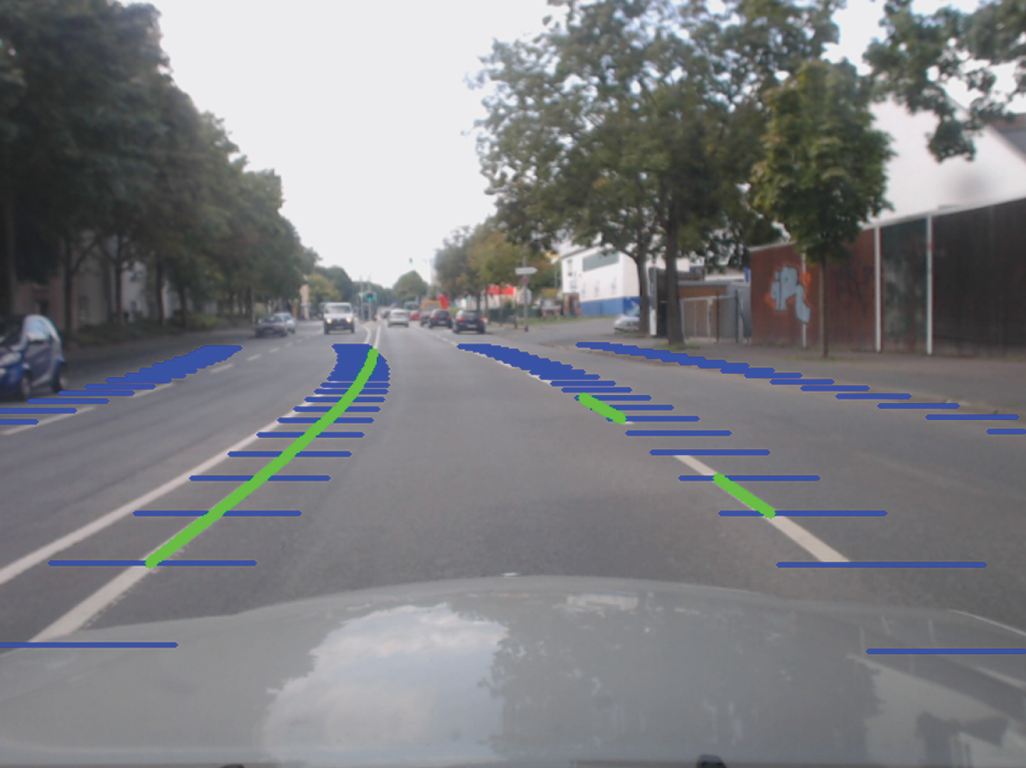
Lane detection.
Performance of lane line detection algorithm in different environments
This chapter difficult for the lane line detected by the line of weakness is studied, and two models, where a model based on fuzzy strong enlargement of LDA, to enhance the contrast of the lane line region, the other is a luminance contrast saliency model, for Lu the strip lane area is extracted. Then, the two models are applied lane detection, lane detection is proposed a method of two-stage: a first stage using the brightness, contrast saliency model to extract the lane line, and select the sample point and a lane line of the road; first two-stage fuzzy LDA zo strong model road image color space conversion, high-contrast enhancement a lane marking image, again using luminance contrast saliency model image after enhancement in lane line extraction, the last used back projection The transformation verifies the extraction result of the lane line. Experimental results show that this method can improve the detection rate of the line of weakness. As can be seen from Fig. 4, our method is better than others on the ROC curve.
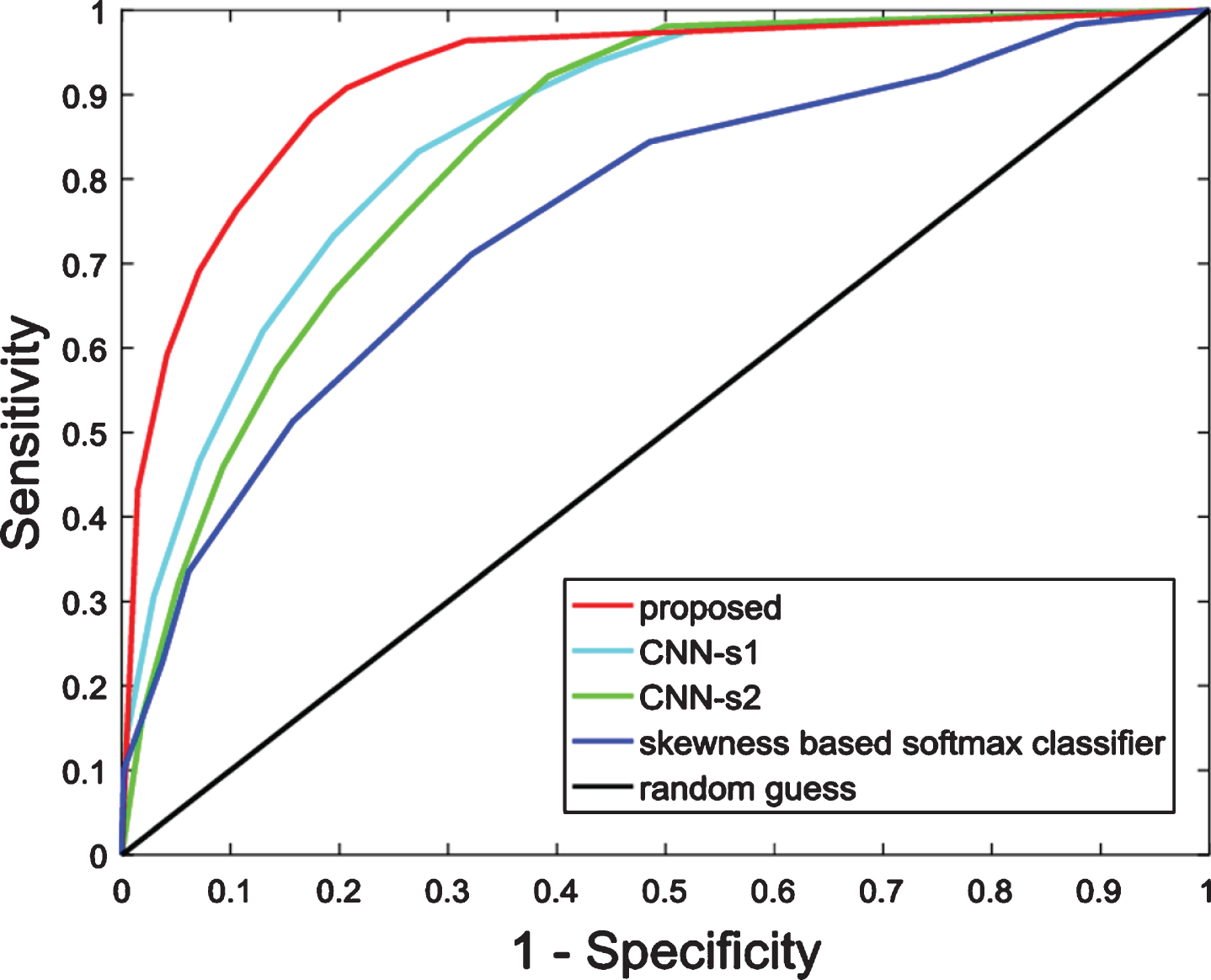
ROC curve comparison of different methods of classification.
Traffic congestion, environmental pollution and other traffic problems can be seen as the contradiction between people, vehicles and roads in essence. Intelligent transportation system is a way to solve this contradiction. In this paper, several key problems in the detection and recognition method of traffic safety information based on monocular vision for intelligent vehicles are studied in-depth, including: in lane detection, a model based on fuzzy LDA intensity and visual saliency is proposed to solve the problem of missing detection of weak lines under complex conditions on highways and urban roads. The lane detection method of type I. First, the lane line is extracted by the visual saliency model; then, the lane line and road sample are selected, and a target elevation model based on fuzzy LDA is designed. The application of this model contrasts with lane line in image significantly improved, effectively highlights the weak line on the road, and uses visual saliency again. The model extracts the second lane line, and finally uses the inverse perspective transformation to further verify the spatial position relationship between the candidate lanes, to find the missing dashed line. Experiments show that this method is 6.3 percentage points higher than similar methods in weak line detection.
Footnotes
Acknowledgment
The work described in this paper was partially supported by National Natural Science Foundation of China under grant No. 51765007, and the Guangxi Provincial Natural Science Foundation of China under grant No. 2016GXNSFAA380111. The authors would like to thank the reviewers for their constructive comments and substantial help that improved the presentation of the paper.