
Abstract
Basketball player detection technology is an important subject in the field of computer vision and the basis of related image processing research. This study uses machine learning technology to build a basketball sport feature recognition model. Moreover, this research mainly takes the characteristic information of basketball in the state of basketball goals as the starting point and compares and analyzes the detection methods by detecting the targets in the environment. By comprehensively considering the advantages and disadvantages of various methods, a method suitable for the subject is proposed, namely, a fast skeleton extraction and model segmentation method. The fitting effect of this method, whether in terms of compactness or quantity, has greater advantages than traditional bounding boxes, and realizes the construction of dynamic ellipsoidal bounding boxes in a moving state. In addition, this study designs a controlled trial to verify the analysis of this research model. The research results show that the model proposed in this paper has certain effects and can improve practical guidance for competitions and basketball players training.
Introduction
With the advancement of science and technology and the rapid development of the intelligent field, the new sensor technology has also made great progress, and the availability and use speed of wearable acceleration sensor technology are increasing rapidly. At the same time, the overall performance is more perfect while the cost is reduced, and the application field is becoming wider and wider. When acquiring athlete information outside the laboratory environment, aspects to consider are heavily influenced and dependent on currently available technologies. Through technological innovation and development, new sensor devices and systems will make it possible to obtain athlete information outside the laboratory environment. At the same time, reductions in size, power requirements and costs will also become a general trend [1]. Wearable sensor technology is also becoming more and more popular in the sports field, which can provide data safely and effectively, promote the development of sports, and meet the needs of coaches and athletes for equipment. In the current decade, wearable sensor technology has developed rapidly in various fields, and sensor usage has also risen in some competitions. It will provide smarter, more real-time and more accurate information, and provide some reference insights for coaches and athletes. In addition, wearable sensors are also used in sports feedback and coaching systems. These systems can be used for training and competition analysis, providing coaches and athletes with real-time, visual, tactile and auditory information, as well as reference data. Coaches, athletes and logistics staff are increasingly benefiting from the use of sensor technology. Many studies at home and abroad have applied wearable sensor technology to sports, such as running, swimming, etc., but there are few reports on the research of wearable sensor technology in basketball sports [2]. Basketball is a sport that requires a constantly changing rhythm and requires speed, acceleration, and explosive power, such as rebounds, layups, jump shots, fast breaks, etc. There is a big gap between China’s basketball technical level and the United States and European basketball powers. Therefore, it is particularly important to strive to improve the technical level of basketball players and train excellent basketball players. In competitive basketball, shooting is an important means of scoring, which is directly related to who will win the final victory. Moreover, in a basketball game, both sides of the game have the goal of winning the ball and winning shots. The shooting rate of both sides of the game will become a key factor in the outcome of the game. Therefore, it is also very important to study the shooting percentage of players [3]. Jump shots and free throws are the basic shooting techniques that are most commonly used and must be mastered in basketball games, and often become the main factors affecting the final result. The jump shot is the most frequently used scoring method in fierce basketball games, and they are also a relatively difficult to master shooting technique. The free throw is the basis of other shooting methods, and the scoring rate of free throws also plays an important role in the final result of the game. Many high-level athletes have excellent free throw percentage and jump shot skills. With the speed of basketball games getting faster and faster, free throws in games may also affect the outcome of the game [4]. At the final moment of the game, the coach can arrange players with high shooting rate and stability to make shots in the selection of shots. In addition, in the offensive and defensive confrontation between the two sides of the game, players must make decisions and act quickly, otherwise the best shot timing will be missed.
Related work
At present, many universities, research institutes or well-known companies in the world have set up research groups or set up laboratories to study moving target detection technology. In recent years, a large number of applications of moving object detection technology in intelligent video surveillance systems have been transformed into products and put into the market [5]. For example: The intelligent video products launched by Axis Network Communications of Sweden include AXIS242SIV video server and AXISIVM intelligent video application module, the intelligent monitoring network of “Perceptrak” launched by Portsmouth, UK, and the SmartCatch intelligent video monitoring system launched by NEC [6]. At present, in the domestic scientific research institutions, the State Key Laboratory of Pattern Recognition affiliated to the Chinese Academy of Sciences is a world leader in visual surveillance research. Its main research is in traffic visual surveillance and pattern recognition. In addition, based on the VIEWS vehicle traffic monitoring prototype system of foreign universities [7], they developed a set of traffic monitoring system with independent intellectual property rights, vstart (Visual surveillance star) [8]. In addition, other domestic universities have also done a lot of research on computer vision technology, such as research on fast image denoising based on approximate geodesic distances of image blocks and object detection based on saliency-driven clustering, etc., which is conducted by the Institute of Image Processing and Pattern Recognition of Shanghai Jiaotong University. Moreover, many well-known companies in China have also done a lot of research work, such as: “Intelligent AI behavior monitoring behavior acquisition camera” developed by Swire Computer Systems, “Railway intelligent analysis solution” developed by Jieshang Company, and the “Intelligent multi-target tracking system (electronic sentinel system)” developed by Guangdong Meidian Bell Technology company, etc., which has achieved good research results. Nevertheless, there are still many problems to be solved in the research of moving target detection technology and visual monitoring. Many domestic intelligent monitoring equipment still come from abroad, and there are still major problems in performance and security, and there are many inconveniences in the later maintenance [9]. At the same time, the current computer vision technology is rarely used in sports professional competitions or examinations, and it is even less used to monitor fixed-point shots in sports professional examinations. The main reason is that the external environment is complicated and image processing is difficult. At present, there is a huge demand in the sports market, especially some items in the examination of sports majors, which is the work we urgently need to study [10].
With the advancement of technology, acceleration sensors have been applied in various industries, such as automobile safety, rehabilitation diagnosis and monitoring, and intelligent products. The literature [11] introduced the application of MEMS sensors in automotive electronics. The article uses acceleration sensors in car safety, and the acceleration sensors are installed on the side and front of the car. When a car collides, it can sense and open the airbag inside the car. Among the MEMS acceleration products, there is a sensor with a range of only 30 g, which can detect the vibration amplitude of the car engine and adjust it with the ignition advance angle control to avoid car engine knocking. In addition, there are sensors installed in the pressure reducer of the semi-active suspension system in the car, which can ensure the car’s driving performance when adjusting the placement and driving on uneven roads. With the continuous development of information technology, acceleration sensors are also gradually applied to the field of sports. The literature [12] applied the sensor device to the 100-meter training of track and field events. Because the time spent in the 100-meter race is short and the movement is fast when running, it is difficult to accurately determine the athlete’s acceleration ability and the power generated by the leg. This literature used many different sensor technologies to effectively record every detail of the athlete’s movements during the 100-meter sprint run, which provides important significance for athlete selection and training. The literature [13] analyzed the application of sensors in smart phones in the sports field, and pointed out that the current sports measurement methods and data statistics methods of campus sports are backward, and the utilization efficiency is not very high. We can use the sensor technology that is already available in smart phones to perform those more tedious measurements. Today, smart phone computing is very powerful and can complete measurements that require multiple calculations. There are many movements in our lives, but no matter how complicated they are, they are composed of basic movements such as running, jumping and throwing. From the perspective of biomechanics, most of them are movement changes or maintenance, and a considerable part can be regarded as changes in acceleration. For example: the vertical jump movement in situ is mainly the strength of the jump. In terms of mechanics, it is how much acceleration the jump force can produce. The literature [14] used acceleration sensors on smart phones to collect acceleration information of vertical jumps in situ, and from an application perspective, discussed how acceleration sensors on smart phones can be used in campus physical exercise. The literature [15] recorded the artificially collected data and video data in parallel with the accelerometer data, compared artificial data with algorithm-derived accelerometer data, and studied the reliability and accuracy of the measurement data derived from the accelerometer.
Force analysis of the model
Basketball players in real life are often exposed to various external and internal forces. The external force refers to the force exerted by the external environment on itself, mainly including gravity, damping force and wind force, and the internal force refers to the force in the internal structure of the cloth, mainly the deformation force of the spring, including tensile force and bending force. This article simulates the above-mentioned common external and internal forces, and the calculation formula is shown in equation (1) [16].
In formula (1), F total F extern , and F intern represent the total force, external force, and internal force on the cloth particle, respectively. Among them, the external force include gravity F gravity , damping force F damp , and wind force F wind d. The internal force includes the spring tensile force F stretch and the spring bending force F bend [17].
The gravity of each particle is F
gravity
, and we calculate it using formula (2).
In the formula, m represents the mass of each particle, g represents the acceleration of gravity, and its size is 9.8N/kg, and its direction in OpenGL is vertically downward along the negative direction of the Y axis.
The damping force F
damp
on the material point of the cloth in formula (1) can be expressed by the Stoke resistance formula of formula (3) [18].
In the formula, m is the mass of the particle, η is the damping coefficient, k is a user-defined positive scalar value, and v is the velocity vector. It can be seen that the direction of the damping force F damp is opposite to the speed v, and its magnitude increases as the speed increases.
For the calculation of wind force F
wind
, first, the sum of wind forces on all adjacent triangular faces of the particle is calculated, and then a random swinging force is added to the mean of the sum as the wind force of the particle, as shown in formula (4):
In the formula (4), λ1λ2λ3 and λ4 are user-defined constants, θ is an angle value, which is used to control the cloth’s swing direction under the action of wind, and rand () is a random noise function, which is used to provide the dynamic effect of random cloth swing. f
wind
(i) represents the wind force on the i-th triangular patch, and the calculation formula is as follows (5) [19].
In the formula, C is the wind coefficient, ρ is the air density, ν is the wind speed, and S i is the area of the triangle patch i.
The correction results for these two cases are shown in Fig. 1. Among them,
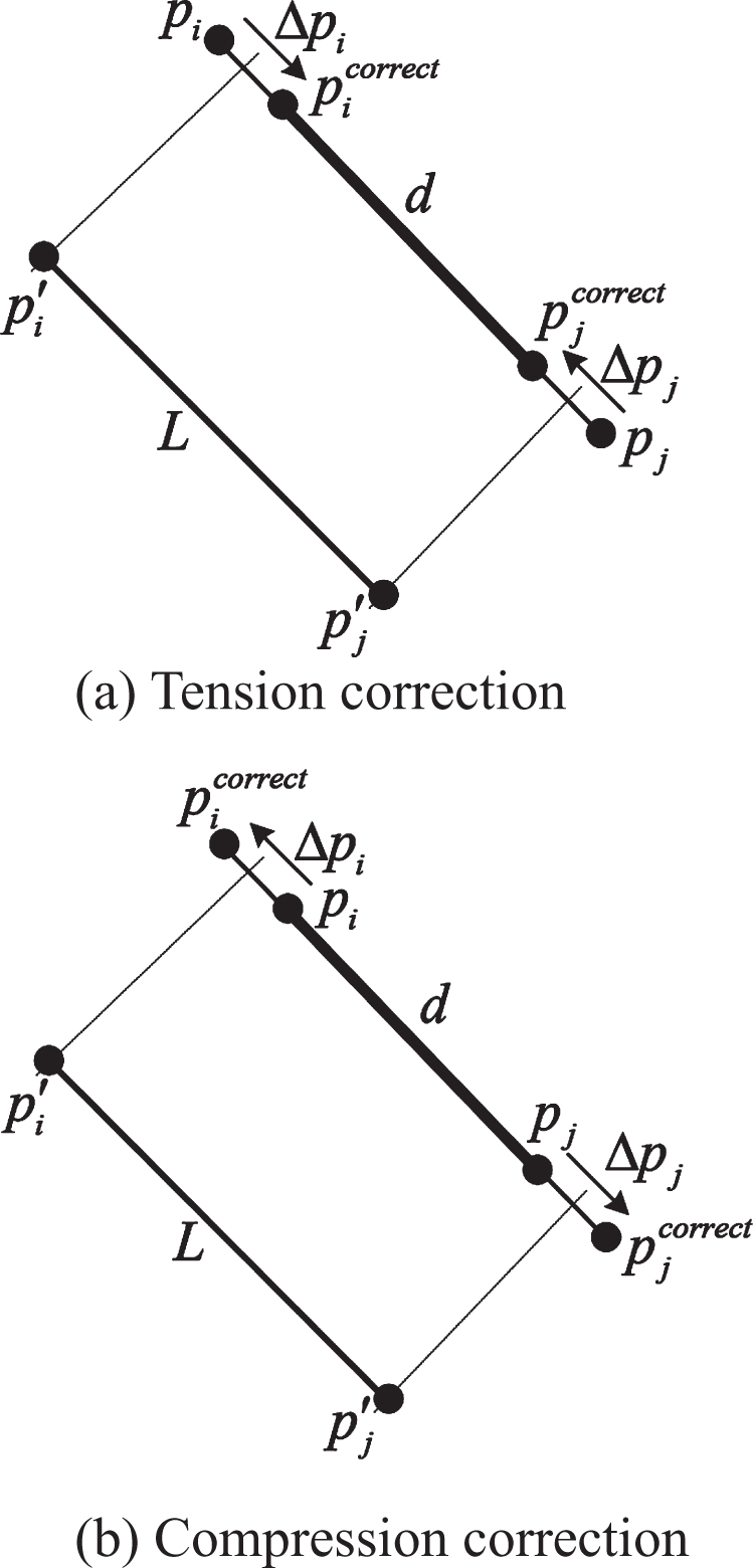
Tension correction and compression correction of spring.
If the current state of a section of spring is known, the position correction vector can be calculated according to formula (6):
In the formula, m
i
and m
j
correspond to the masses of the mass points p
i
and p
j
, and L represents the length of the spring in its natural state. It can be seen from the above formula that when ∥p
i
- p
j
∥ > L, the direction of Δp
i
is opposite to p
i
- p
j
, and the direction of Δp
j
is the same as p
i
- p
j
, and the spring performs compression correction. When ∥p
i
- p
j
∥ < L, the direction of Δp
i
is the same as p
i
- p
j
, and the direction of Δp
j
is opposite to p
i
- p
j
. If the mass of any particle at both ends of the spring is set to 0, it can be controlled whether to perform spring correction. After the position correction vector is obtained, the positions of the particles at both ends after the correction can be calculated. The specific calculation formula is shown in formula (7) [21–23]:
The research results show that although there are differences in human race and gender, the proportion of the size and height of each part of the human body has a certain stability and will not change greatly with changes in human height or posture. Therefore, this article studies and analyzes GB / T 10000-88 “Chinese Adult Body Size” and GB / T 13547-92 “Work Space Human Body Size”. Moreover, for the human joint size customized in this article, the linear relationship between the size of the human body part and the height H is calculated in this paper, as shown in Table 1. Based on this relationship, the size and length of each part of the human body can be determined initially, and then the positions of relevant feature joint points can be calculated.
The linear relationship between human body size and height H
The linear relationship between human body size and height H
As for the feature points of the virtual human model, this paper divides them into three types: end feature joint points, middle feature joint points and inner feature joint points, from outside to inside. First, the end feature joint points are extracted. Then, based on the linear relationship between the size of the human body part and the height H and the Dijkstra (Dijkstra) approximate geodesic distance algorithm, you can quickly locate the characteristic joint points of the middle layer of the model. Finally, the joint points of the inner layer of the model are calculated through the characteristics of the human body structure. According to the definition of these feature points, the human body model can be divided into six parts: torso, left and right upper limbs, left and right lower limbs and head. Figure 2 is a schematic diagram showing dimensions of characteristic joint points and parts of a human body model.
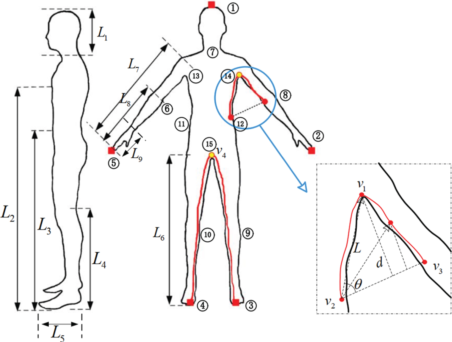
The Schematic diagram of the dimensions of joint points and parts of human body.
Because the model used in this article stands along the positive direction of the y-axis, we only need to find the maximum Y
MAX
and minimum Y
MIN
for all vertices of the model according to their y coordinate values to obtain the height of the human body:
The terminal joint feature points of the human body model are automatically extracted. The terminal joint feature points represent the outermost vertices of the model, including the apex of the head and five parts of the limbs. The correct extraction of the terminal joint feature points is the key to the correct extraction of the remaining joint points in the model, and it is also an important factor for the model segmentation. The points from left to right in Fig. 3 are the extraction results of the joint points at the end of the human model.

Extraction results of terminal feature points.
After obtaining the outermost feature joints of the model, the next step is to calculate the middle feature joints and inner feature joints of the model. We will first calculate the position g where the hip point is located, which uses the point corresponding to half the length of the geodesic distance between the two toe feature points, that is, the point v4 in Fig. 3. The model’s leg length L5 is approximately replaced by the geodesic distance g (v4, v leg ) from the point of the toe to any point of the toe.
For the calculation of the coordinates of the joint points where the elbows, knees, and necks are located, this paper uses the average of all vertex coordinates on the geodesic distance contour as the joint points of the corresponding parts. For the convenience of description, only the specific calculation method of the left elbow joint point is given, and the joint points of other parts can be calculated by the same method.
The first step is to use the characteristic point of the left hand end as the reference point, and assign the forearm length L7 to f (H) as the judgment distance;
The second step is to detect all triangles on the model, check the geodetic distance between the three vertices of the triangle and the left fingertip point v L , and determine whether there are vertices that satisfy the formula g (A, v L ) > f (H) , g (B, v L ) < f (H);
In the third step, if the above conditions are satisfied, the coordinate of the point d1 can be calculated according to formula (9). Similarly, the coordinate of the point d2 can also be obtained;
The fourth step is to find the coordinates of the intersections of all triangles that meet the conditions to form a set of intersections to connect the intersections on the connected triangles in turn to form an isopleth, which is called the geodesic distance isopleth. Finally, the average value of the coordinates of all vertices in the set of intersections is calculated, and the average value is used as the coordinate of the left elbow joint point.
In the formula, x vj y vj z vj is the three-dimensional coordinate of the vertex, N i is the total number of vertices in the i-th intersection set, x i y i z i is the three-dimensional coordinate of the i-th joint point, and M is the total number of joint points. Similarly, through the above calculation method, the coordinate of the joint points where the right elbow point, left knee point, right knee point, and neck point are located can be obtained.
In this article, the waist outer points on the left and right sides of the human body are defined as the vertex v2 with the largest Euclidean distance from the hip point on the isopleth where the waist height L3 is located. Then, the following formula exists.
In the formula, v2 represents the left waist outer point, p i represents a certain point in the set T, v4 represents the left condyle point, and T represents the set of all vertices included in the left waist isopleth formed by using the left toe point as a reference point. Due to the left-right symmetry of the human body, the same method can also be used to extract the outer waist point on the right side of the human body.
Precise extraction of model axillary points is a prerequisite for accurately extracting shoulder joint points and dividing model arms. By observing the structural characteristics of the human body, it can be found that the axillary point, waist point and elbow point located on the same side of the model always form a triangle, as shown in Fig. 2. v1v2v3 corresponds to the axillary point, the external point of the waist, and the elbow point, and there is such a rule: There is always a point v1 on the line of geodesic distance where v2 and v2 are located, so that the distance d from point v1 to v2v3 is the largest. We call v1 that meets this condition as the axillary point. Therefore, the process of solving the axillary points is transformed into solving the problem of the maximum distance from a point to a straight line.
When
Finally, the vertex of the geodesic distance of the waist and elbow points is traversed in order. The formula (15) is used to calculate the d value of the corresponding vertex, and the vertex coordinate corresponding to the maximum value of d is used as the axillary point of the human body model. The geodesic distance g (v1, v L ) from v1 to the feature point v L corresponding to the left fingertip is the model arm length L6. After obtaining the exact model arm length, the shoulder joint point coordinates can be quickly calculated using the same method as the elbow joint point.
After obtaining the semantic feature points of the human body, the hierarchical segmentation of the three-dimensional human body model can be completed through geodesic distances. For the convenience of description, we set the vertex set formed by the 3D model as:
In the formula, v
i
is the i-th vertex of the human body model, and N is the total number of triangles. The ultimate goal of model segmentation is to divide all vertices S of the three-dimensional model according to their structural characteristics. Taking arm segmentation as an example, according to the terminal feature joint point p
i
and the adjacent inner feature point v′, it can be known that the vertices belonging to the arm part are:
Similarly, under the constraints of the feature points, the leg and head segmentation results can be obtained, and the remaining vertices constitute the torso part of the human body model. After that, the torso was divided into 6 parts based on the waist, chest height, and the vertical line connecting the left and right axillary points. Finally, for the limbs of the model that have been segmented, the corresponding mid-level feature points are found to form a set of sub-parts that require secondary segmentation. According to formula (16), it is divided into two parts again to complete the semantic segmentation of the model, which can better reflect the structural characteristics of the human body.
The model joint points extracted through the above steps lack the joint point coordinates of the torso part. For this reason, this paper compares the positions of model joint points in the motion capture data BVH format file and calculates the skeleton point coordinates separately for the human torso. The steps for extracting the skeleton points of the torso are as follows:
Step 1: All vertices contained in the 6 branch regions of the model torso are stored in 6 different containers, respectively;
Step 2: The coordinates of all the vertices in each container are traversed separately, the average value of the coordinates inside each container is obtained, and the average value of the coordinates of the left and right shoulder regions is used as the skeleton point coordinates of the region;
Step 3: The average values of the coordinates of the left and right sides of the chest and the left and right sides of the waist are calculated again, and the calculated final average value is used as the skeleton point of the corresponding area.
In view of the characteristics of the Aixe Align Bounding Box (AABB) that has a low degree of fit to the surface model and the intersection detection test of the Oriented Bounding Box (OBB), this paper uses an ellipsoid that is more suitable for radian surfaces as the model’s primitive bounding volume. The three-dimensional model point set S generates Minimum Volume Enclosing Ellipsoids (MVEE), that is, this method transforms the calculation of the minimum volume surrounding ellipsoid into a convex optimization problem, which has the following properties:
In formula (17), ɛQ,c represents an ellipsoid, which is represented by an 3 × 3-dimensional positive definite matrix Q and a center c. Among them, the eigenvector and eigenvalue of Q are the semi-major axis direction and the semi-major axis length of the ellipsoid, respectively. In formula (18), MVEE (S)/d represents scaling 1/d around the center of MVEE (S), and conv (S) is the convex hull of S.
The pre-processed human model is divided into multiple different regions PS ={ S1, S2, ⋯ , S
j
, ⋯ S
k
} according to semantics, which ensures the consistency of the segmentation results and the human topological structure. In the process of fitting the ellipsoid of the sub-region S
j
, in order to effectively evaluate the fitting of the generated ellipsoid, it is necessary to numerically represent the approximate error between the fitted ellipsoid and the sub-region. Since the human body model has been segmented semantically in this article, the ellipsoid already has good fitting characteristics. It only refines the ellipsoid in the local area and does not need to accurately calculate the error value. As shown in formula (18), the fitting error can be approximated by calculating the average value of the radial distance between the surface point of the human model subregion and the approximate surface.
In the formula, E s j represents the ellipsoid fitting error of the model subregion S j , v i is the ith vertex of the surface points of the subregion, K is the total number of vertices contained in the subregion, and φ s j (v i ) is the radial projection point of the vertex v i on the surface of the ellipsoid, ∥· ∥ represents Euclidean distance.
As shown in Fig. 5, if the initial k value of the K-means clustering is equal to 3, vp,1vp,2 and vp,3 are the cluster centers corresponding to the previous step, and

Geodesic distance equivalence points.
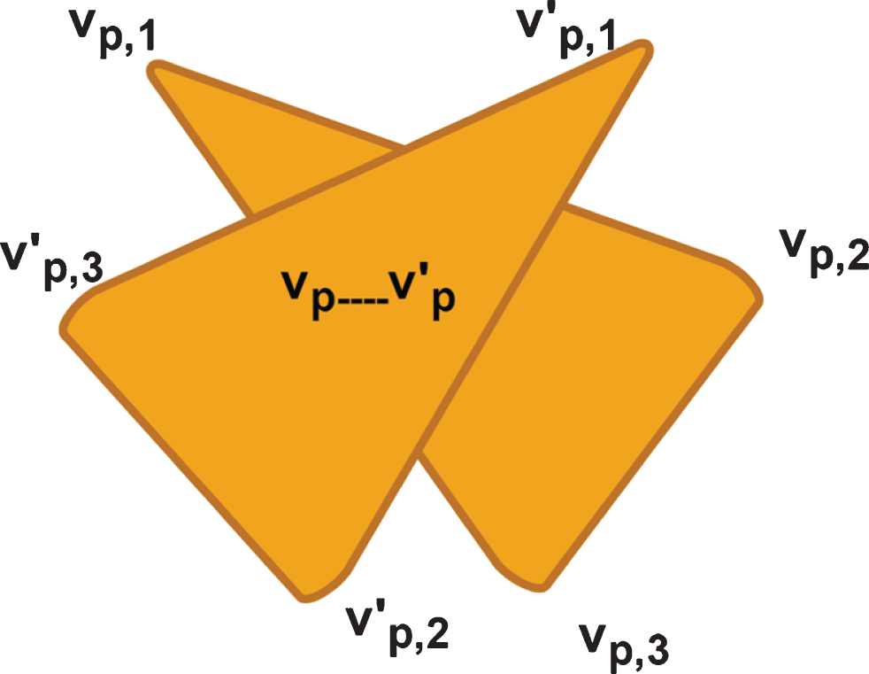
Schematic diagram of cluster termination conditions.
In formula (19),
In order to ensure the results and efficiency after the second division, this paper uses Euclidean distance as the clustering criterion, and increases the k value and the center one by one while pruning optimization, and judges whether the fitting error E s j ⩽ μ of the ellipsoid is satisfied. μ is a preset threshold. If the conditions are met, the segmentation will stop.
In order to make the fitting error E
s
j
converge, in the clustering process, when reclassifying the points, it is necessary to add limiting conditions:
In formula (20), E s i and E s j are the fitting errors of ellipsoids i and j (i ≠ j), respectively. The ellipsoid i is the ellipsoid where the point is currently located, and the ellipsoid j is another ellipsoid bounding box.
As shown in Fig. 6, the three axis vectors of the world coordinate system O are x (1, 0, 0) , y (0, 1, 0) , z (0, 0, 1) and the origin coordinate is O. The three axis vectors of the child coordinate system p are r (rx, ry, rz) , u (ux, uy, uz) , d (dx, dy, dz), the origin coordinate m of the child coordinate system is p (px, py, pz), and the transformation from the world coordinate system to the child coordinate system mainly includes the following 4 steps:
The world coordinate system x-axis is rotated until the sub-coordinate system r-axis vector is parallel; The y-axis of the world coordinate system is rotated until the u-axis vector of the sub-coordinate system is parallel; The world coordinate system z axis is rotated until the d axis vector of the sub coordinate system is parallel; The world coordinate system origin o is translated to the child coordinate system origin p.
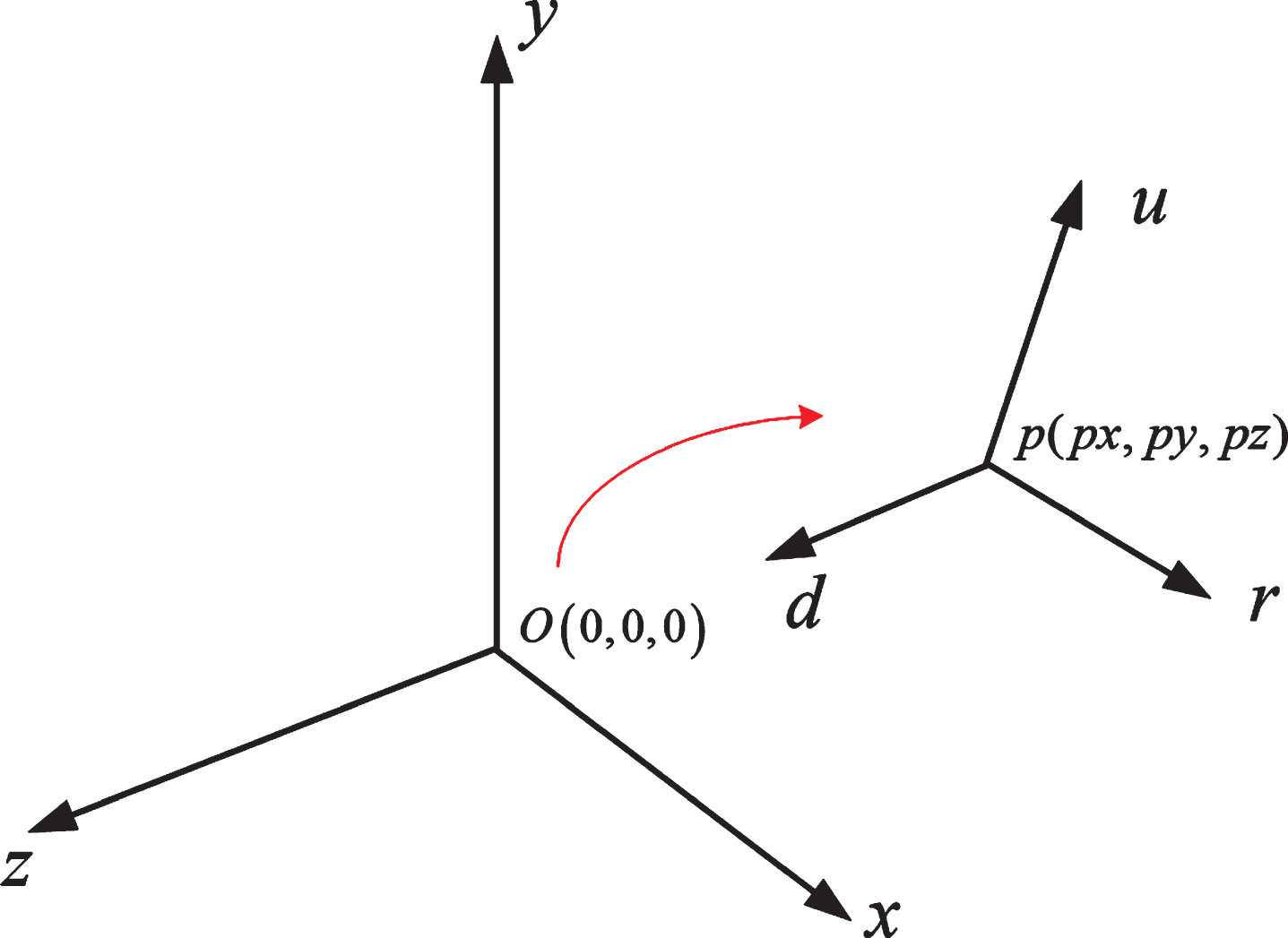
World coordinate system and child coordinate system.
We divide it into two phases of rotation and translation, namely, T = Rot × Mov. Therefore, the sub-coordinate system that coincides with the world coordinate system is first rotated at the origin, and then translated to obtain the transformation matrix T.
For the convenience of calculation, we set the rotation matrix to Rot and express it as formula (21):
Therefore, the following formula exists:
By combining the formula (22), (23), and (24), the formula (25) can be obtained:
From the formula (25), the calculation formula of the rotation matrix Rot can be obtained, as shown in formula (26):
In order to enable the rotation matrix Rot to be applied to the rotation calculation of the vertex, the rotation matrix Rot is extended to the 4 × 4 rotation matrix Rot of g, as shown in formula (27):
The transformation matrix T is obtained by first rotating and then translating:
This study collects video of shooting in three directions of left, middle, and right, and each direction of video is divided into ten groups of data, and the length of each group of data is about 1.5 minutes. Moreover, this study uses the Hough circle transform method to achieve accurate detection of the basket, and uses a combination of background difference and three-frame difference algorithm to realize basketball detection and image calibration technology to realize basketball goal recognition.
Through comprehensive analysis of the three simulated test videos of the left, middle and right shots, the basketball was detected from the video sequence frame images. After analyzing the video of the left, middle and right shots, it is concluded that the image of adjacent frames will have a certain position change, and the basketball will gradually become smaller when it enters the hoop.
By testing 30 sets of data, that is, 10 sets of data for each of the left, middle, and right, the test results are shown in Table 2 to Table 4, and the statistical graphs are shown in Figs. 8 10:
Statistical table of left shots
Statistical table of left shots
Statistical table of mid shots
Statistical table of right shots
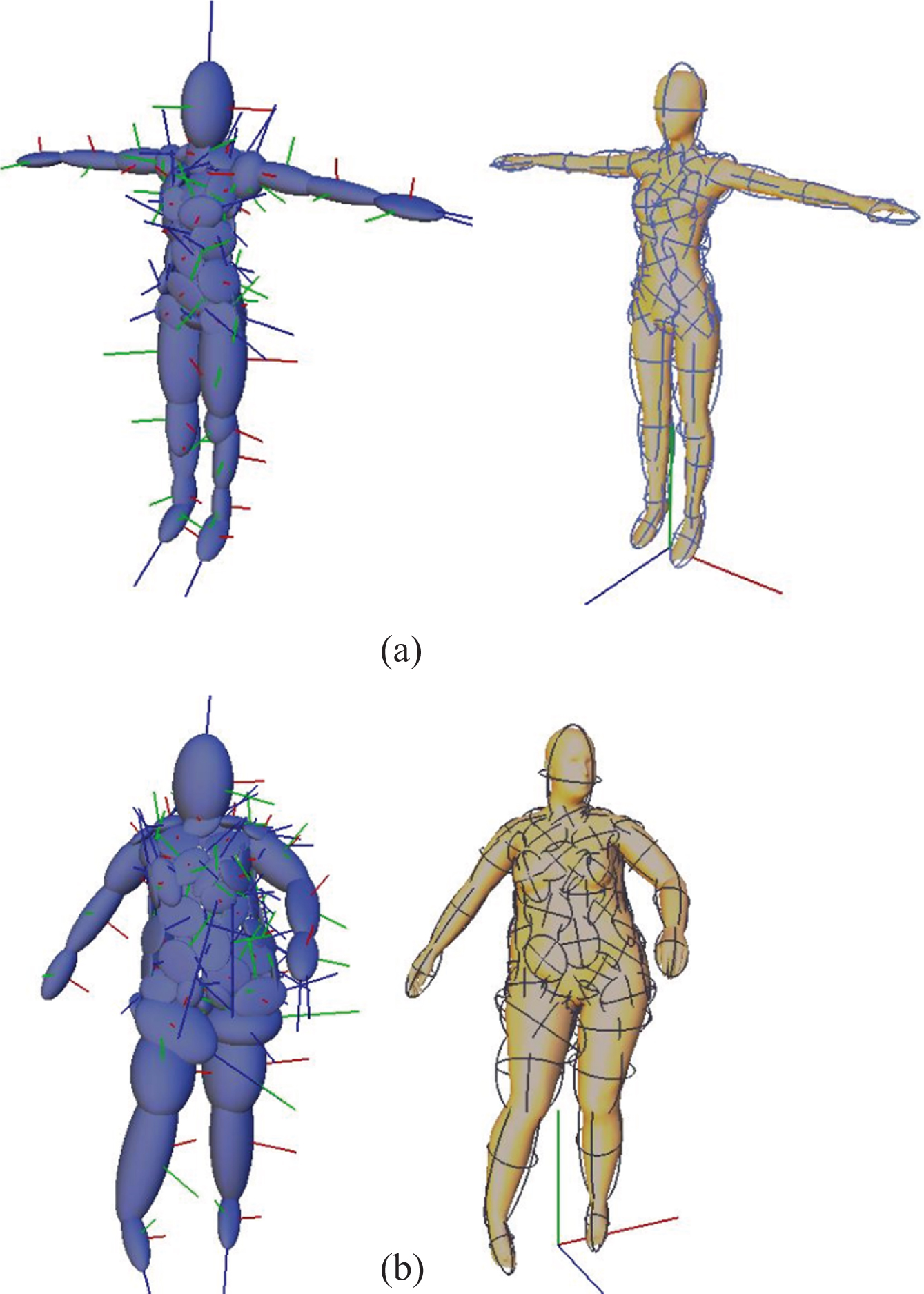
Ellipsoid fitting effect.
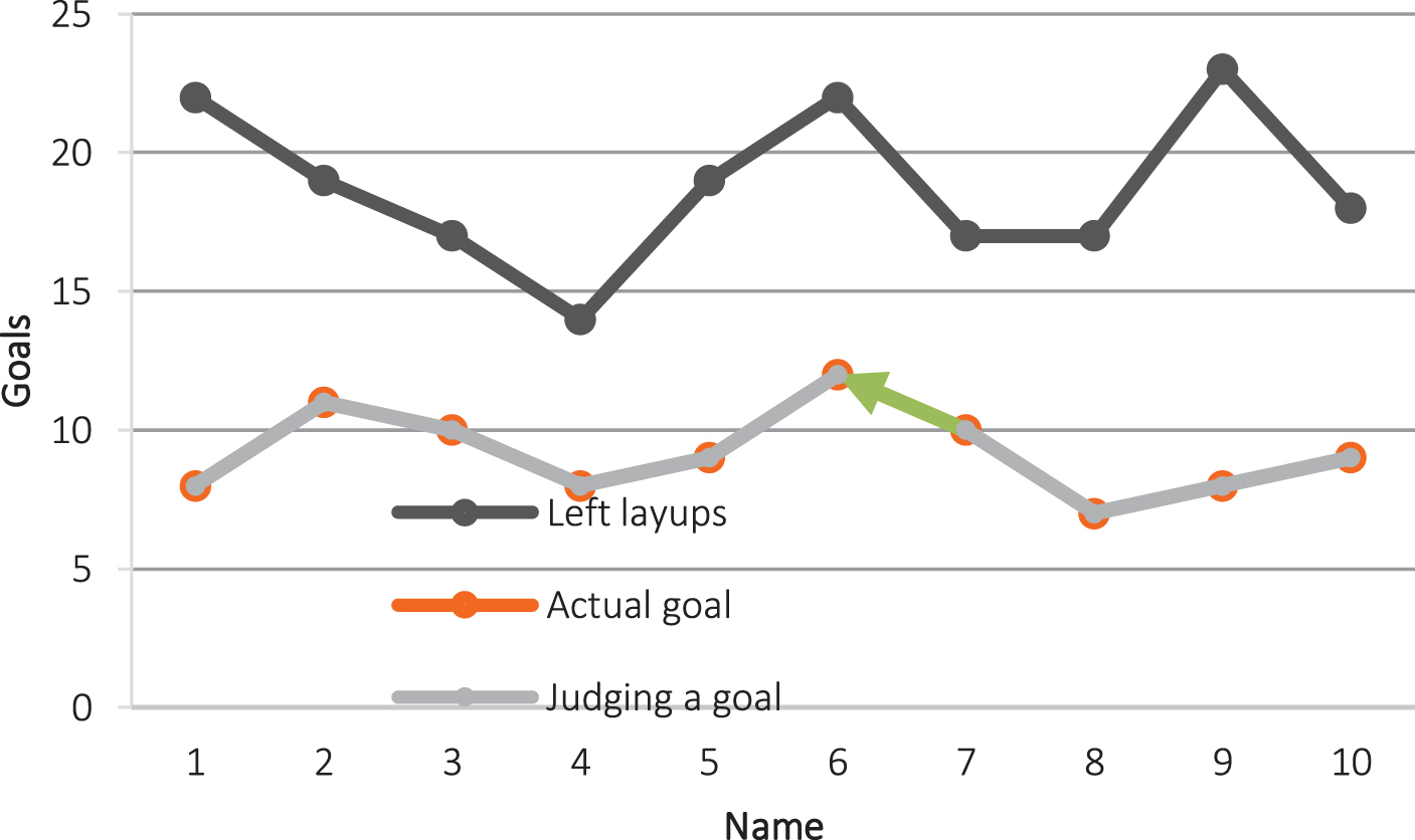
Statistical diagram of left shots.

Statistical diagram of mid shots.
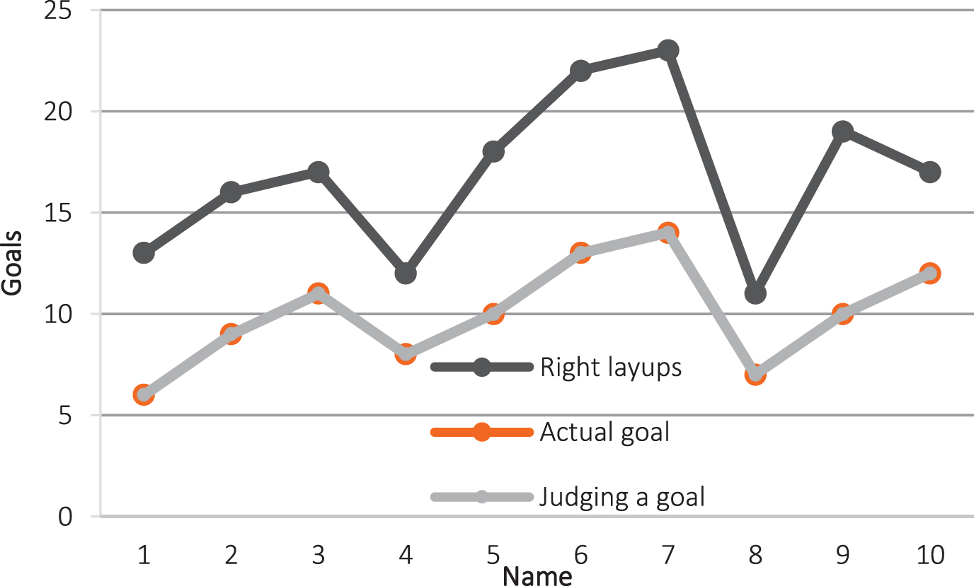
Statistical diagram of right shots.
In the ten sets of data of the left, center and right shots, it was found that there was no misdetection or omission in the left and right shot data. However, in the shot data, the data of third and ninth groups are partially missed. This article is to determine the basketball and system configuration parameters again by delaying the appropriate time after the basketball enters the basket, so as to solve the misdetection situation. However, the basketball thrown in the middle position may be directly thrown into the hoop (hollow ball) and moved along the direction of the connection between the hoop and the rebound. In this case, there will be a missed inspection phenomenon, which is a work to be further studied in the future.
Based on the linear relationship between body part size and height and human body structural characteristics, a fast skeleton extraction and model segmentation method is designed in this paper. The entire process does not require human intervention and the positions of skeleton joints are accurate. Moreover, on the basis of model segmentation, this study uses ellipsoid as the primitive bounding box to design a fast fitting method of dynamic human model based on template frame information labeling The fitting effect of this method has greater advantages than traditional bounding boxes in terms of compactness and quantity, and the method realizes the construction of dynamic ellipsoidal bounding boxes in the state of motion. In addition, this study collects video of shooting in three directions of left, middle, and right, and each direction of video is divided into ten groups of data, and the length of each group of data is about 1.5 minutes. Finally, this study uses the Hough circle transform method to achieve accurate detection of the basket and uses a combination of background difference and three-frame difference algorithm to realize basketball detection and image calibration technology to realize basketball goal recognition. The research results show that the method proposed in this paper has certain effects.