
Abstract
Usually the highlights can be calculated with the specular term of the bidirectional reflectance distribution functions developed for glossy or matte materials. However, as for the translucent materials, complex appearance could be caused by the scattering of light inside the medium. An efficient highlight generation model is presented to simulate the highlight effects on smooth or rough surfaces or around the boundaries of objects made from translucent materials. The presented model is derived from the directional dipole model approximation of the diffusive part of the bidirectional scattering surface reflectance distribution function. Unlike the previous specular reflection models, the presented model builds a relationship between the highlights and the scattered lights inside the medium by considering the refracted ray of the incident point and the ray toward the emergent point, which could represent the variation in fluence due to the internal scattering at the surface. By integrating a rendering process with the directional dipole model, the resulting highlight effects term could be represented in a similar way by the specular term of a bidirectional reflectance distribution function model. The number and the strength of the generated highlight pixels were compared among typical highlight generation models. It is demonstrated that the presented model could generate highlight effects at the appropriate positions and enhance the perceptual translucency of specific edge areas greatly.
Keywords
Introduction
The surface shape of an object can be depicted by highlights, since they could provide important cues for identifying surface protrusion and depth and determine specific surface structures even if two surfaces overlap. Since the translucent materials exhibit a smooth and soft appearance, thin details and edge features are usually lost or blurred due to the ambiguously reflected light intensity. However, the lit up thin geometric detail is a distinct feature of the appearance in the rendering of translucent materials [1].
Though realistic facial appearance could be estimated and synthesized from textured meshes [2], traditionally, models based on a bidirectional reflectance distribution function (BRDF) are used to simulate materials that have either glossy or matte appearances. A BRDF model usually contains a diffusion term and a specular highlights term, where the specular highlights can faithfully reflect the appearance of objects with rough or smooth surfaces. However, the BRDF models alone are inadequate to reproduce the appearance of the translucent materials, in which most of their appearance comes from the internal scattering of light. Even though some BRDF models [3, 4] with a diffusion term accounts for subsurface scattering, they actually simulate subsurface reflection rather than light transport beneath the surface.
Based on the microfacet reflections inside specular v-grooves [5, 6] or the volume scattering analogous to Smith model [7], the BRDF models could capture color variation in the v-grooves [8] and produce a more realistic appearance at a surface point with spatially varying roughness. Though these models have incorporated multiple reflections, they are not suitable to simulate light transport beneath surface of the translucent materials.
Jensen et al.’s dipole model could describe the light transport between any two rays intersecting with the surface at different points in a semi-infinite plane medium [9]. Donner and Jensen described the roughness of the surface on top of multi-layered translucent materials with a Torrance-Sparrow BRDF [10]. Okamoto et al. addressed the subsurface scattering on a curved surface by the curvature-dependent reflectance function [11]. All these models did not consider the directional scattering on the approximated subsurface scattering for the translucent materials, thus the volumetric effects cannot be directly simulated by them. Surface details are usually removed in the relatively flat-looking rendering result, and the translucency is also lost to some extent.
In this paper, a highlight generation model based on the directional subsurface scattering configuration will be introduced. The proposed model is derived from Frisvad et al.’s directional dipole model [12], assumes that the scattered light of the incident and the emergent light can generate highlight effects at the exitant point, and the concept from the highlight component in the BRDF model is also adopted to derive the expression of highlights.
The key contributions of this work can be summarized as follows. (1) A model based on the directional subsurface scattering configuration is developed to produce highlight effects in the rendering process of the translucent materials. (2) By comparison with the ground truth reference, the generated highlights are located appropriately on the edge areas as well as smooth and rough surfaces, providing cues for shape and translucency perception in the edge regions that have geometric sharpness. (3) The proposed model performs better than the typical highlight generation models in metrics of number, strength in the selected regions.
Related work
In this section, the relevant work on estimating the reflectance profiles based on subsurface scattering for the translucent materials are reviewed.
The BRDF models express the highlight component as a specular reflection from smooth or rough surfaces, thus the highlights can occur due to single or multiple reflections of the incoming light on a surface [3, 13]. The highlight effects for translucent materials with the scattering light on surface points were generated to help preserve shape details, however the light scattering inside the medium is not considered [14]. For the translucent materials, the subsurface scattering can also contribute to modeling highlight. Based on subsurface reflectance, Hanrahan and Krueger presented a reflectance model with diretional scattering, which could cause subsurface reflection varying in different directions [15].
When estimating the profile of multiple scatterings inside a medium, some methods necessarily involve the incoming and the outgoing light directions. The DISCO method can capture the translucent material models with local illumination variation and significant detail due to directionally dependent light sources [16]. Xin Tong et al. decoupled mesostructured entrance and exiting functions with the light direction dependence to obtain the global subsurface scattering [17]. However, other methods do not depend on the directions of the incoming and the outgoing lights. Hašan et al.’s model can specify a desired reflection profile for stackings of base materials [18]. Song et al. edited the measured heterogeneous subsurface scattering by ignoring the angular dependencies of the incoming and the outgoing lights [19].
When estimating reflection and transmission on rough surfaces for the translucent materials, the reflection and the refraction at the skin’s boundaries are modeled as isotropic rough surfaces [20]. d’Eon and Irving’s [21] and Donner and Jensen’s [10] diffusion estimations can account for rough surfaces by replacing the Fresnel functions with an appropriate BRDF. Frederickx et al.’s forward scattering dipole model could generate highlights with an approach aware of the roughness reflection [22].
Our work aims to make the sharp features of the translucent material objects maintained and perceptible by generating highlight effects on the rough surfaces. The architecture of the presented model is detailed descripted in Section 4.
Light diffusion in translucent materials
The light scattering in the translucent materials is presented by the bidirectional scattering surface reflectance distribution function (BSSRDF),
In computer graphics, the light scattering inside a medium is described by the radiative transfer equation (RTE),
where L is the radiance, σ
t
is the extinction coefficient, σ
s
is the scattering coefficient,
With the diffusion approximation into the radiative transfer equation, the diffusion equation can be derived. The classic diffusion equation is
where D is the diffusion coefficient, Q0 (x) and
where ϕ (x) =0 if
To solve Equation (3) in the radiative transfer, the fluence rate can be set equal to zero at the physical boundary under the Zero-Boundary condition. In the standard dipole, the expression of the fluence rate is.
In the directional dipole model, the BSSRDF is approximated as the diffusion and delta-Eddington term. If the estimation point is not too close to sources and boundaries and the absorption coefficient is far less than the scattering coefficient, the expression of the diffusion fluence rate is

Configuration of the directional dipole model.
There is a more accurate solution to the diffusion term if the fluence rate vanishes at the extrapolated boundary. This extrapolated boundary is located in the normal direction outside the medium, and the distance from the geometrical boundary is called the extrapolation distance d
e
. If the interface is between tissue and unscattering medium with similar refractive index,
In the directional dipole model, the real source is mirrored by a modified tangent plane with a normal vector
The positions of
The proposed model consists of four stages. First, the directional dipole model is applied to set up the displacement of the real source and the virtual source and then the approximated BSSRDF value of the material can be obtained. Second, with the directional scattered ray of the incident light and the ray toward the emergent light, the local orthonormal frame is chosen to obtain the parameterization for the highlight effects generation model. Third, two functions M and D are defined to calculate the highlight effects term. M is a combined function including Fresnel and geometrical attenuation factor terms, and D is a normal distribution function. Last, the resulting highlight effect is the highlight effect value generated by the real source minus the value generated by the virtual source.
Subsurface scattering with directional dipole model
The following notations are used in Fig. 1. The incident light at location x
i
from direction

Flow chart of the proposed highlight effects generation model.
To generate the highlights by the directional subsurface scattering configuration, a local orthonormal frame similar to the BRDF parameterization is defined. The vectors
The orthonormal frame is important since we found that the angle constraint with the orthonormal frame obviously affects the translucency appearance.
In the experiment,

Highlights’ relation with the vectors
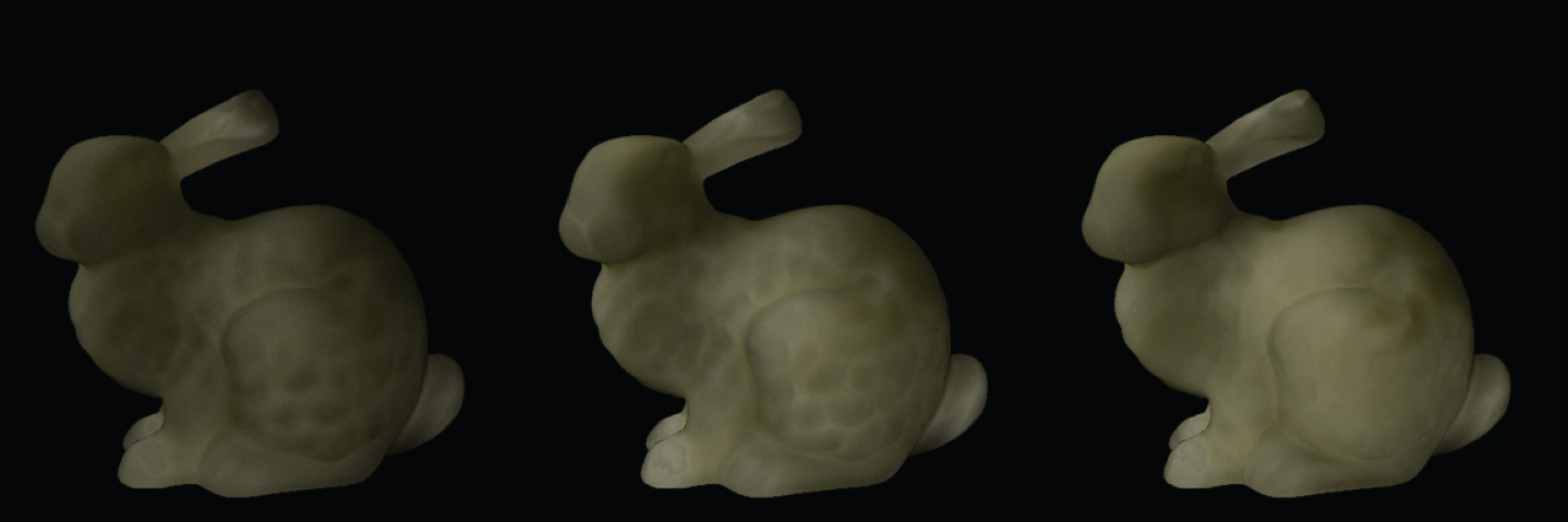
Rendered images of apple material using different refraction directions of incident light within the orthonormal frame. From left to right:
By employing the orthonormal frame, more control over the translucency appearance could be obtained, and even if the results are not better than other frames, it would be flexible to generate the highlight effects under different translucency conditions.
The specular highlight term of BRDF can be expressed as [23].
where M is a combined function including Fresnel and shadowing terms.
The definition of
The directional dipole model displaces two sources to calculate the diffuse reflectance, and the final form of the BSSRDF uses the real source term minus the virtual source term. Therefore, the highlight effects are defined as the real source term minus the virtual source term, which can produce a more obvious highlight shape. The expression of the highlight effects is
For the real source,
For the virtual source,
The generated highlight effect
The total highlight effects are the real source highlight effects minus the virtual source highlight effects.
Our model fits the ray tracing framework and can be integrated over incident lights with a Monte Carlo method.
Generated highlight effects experiment
The bunny object is used in the highlight-evaluation experiment. Two regions are selected on the bunny object, one is in the head area, the other is in the leg area. Both regions have obvious rough and convex surface features and boundaries with variable protrusion.
Four materials from Jensen et al. [9], and Narasimhan et al. [24] are employed to perform the directional-dipole-based rendering and generate the highlight effects. They are marble, chocolate milk (regular), apple, and whole milk.
Our highlight effect generating model is compared with the traditional BRDF-based highlight generating models, including Ashikhmin model [25], Ward model [26], Schlick model [4], and as well as Szirmay model [27], since our model and these models generate highlight effects on similar geometrical regions.
These highlight generating models have been evaluated in two distinct object areas. Figure 5 shows the head area of the bunny with roughness on the mouth and a smooth boundary on the left side of the face. It also shows the boundary of the bunny’s leg areas.
According to one work [28], the “percentage of highlight area” is a particular type of statistics that is highly correlated with surface glossiness, and it is defined as the ratio of the total number of highlight pixels to the total number of surface pixels. The number of highlight pixels is chose as one metric to evaluate our generated highlight results. The other metric chosen were “strength,” which refers to mean highlight pixel intensity.
Generated highlight effects quality
For marble and chocolate milk (regular), the highlights on regions with roughness generated with different models are shown in the red closeups of the first and second columns in Fig. 5. It is apparent that the Ashikhmin, Ward, Schlick and Szirmay models clearly have smaller numbers of highlight pixels, and their strength values are also smaller except the Szirmay model (Table 1 documents the highlight numbers and strength values). Consequently, they cannot display the perceived gloss appearance appropriately in the area of the bunny’s mouth. Our model has the largest strength value, which can clearly display the protrusion in the area of the mouth. In the purple closeups of the first and second columns in Fig. 5, the Ashikhmin, Schlick and Szirmay models have larger values in the number of highlight pixels and strength, they generated obvious highlights on the side of the face. For the Ward model, with fewer highlights and less strength, the generated highlight effect is not significant. If a cube is illuminated from directly behind, there would be a bright appearance in the fringe around the thin edges, where light passes through, therefore, for the slowly changing curvature edge, the highlight effect should not be obvious [29]. Our model has the smallest value on this area, thus it correctly handles the low-curvature boundary of the left side of the bunny’s face.
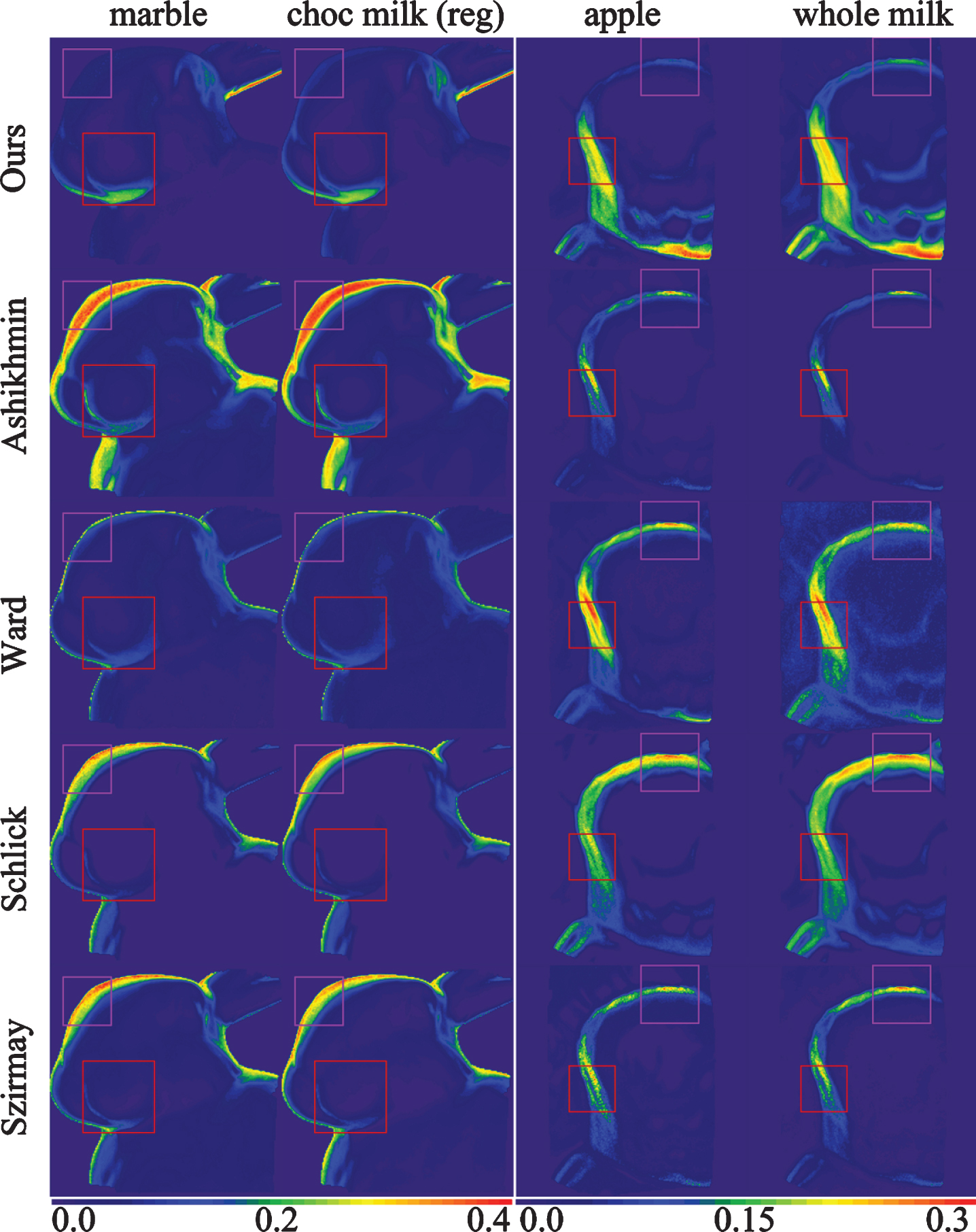
Highlights generated by different models. The red closeup shows a region with a rough boundary region, and the purple closeup shows a smooth boundary region. The first column shows the results for marble material, the second column shows the results for chocolate milk (regular) material, the third column shows the results for apple material, and the fourth column shows the results for whole milk material.
Highlights number and strength of each generation model in 4 material objects. (Object region number, 1-1: the red closeup of first and second columns in Fig. 5; 1-2: the purple closeup of first and second columns in Fig. 5; 2-1: the red closeup of third and fourth columns in Fig. 5; 2-2: the purple closeup of third and fourth columns in Fig. 5)
In the red closeups of the third and fourth columns in Fig. 5, for the apple material, the Ward model generates a larger number of highlight pixels and a higher strength value than the presented model in the boundary of the bunny’s left front leg, where the curvature value changes steeply. In the purple closeups of third and fourth columns in Fig. 5, the presented model generates a smaller number of highlight pixels and a lower strength value than the Ward model, since the curvature changes slowly on the boundary of the bunny’s upper-front leg. Compared with the Ashikhmin, Schlick, and Szirmay models, the presented model has more reasonable values on numbers and strength of highlight pixels in both the red closeups and the purple closeups, increasing the perceived gloss in the boundary of the bunny’s front leg.
Figure 6 show the bunny object rendering results after adding highlight effects by the presented model and other widely used models. Generally, the impression of the bounding contour and edges are more visible with the highlight effects, especially in the bunny’s mouth and leg areas, while without adding highlight effects, the shapes of the contour and edges are blurred and hidden.
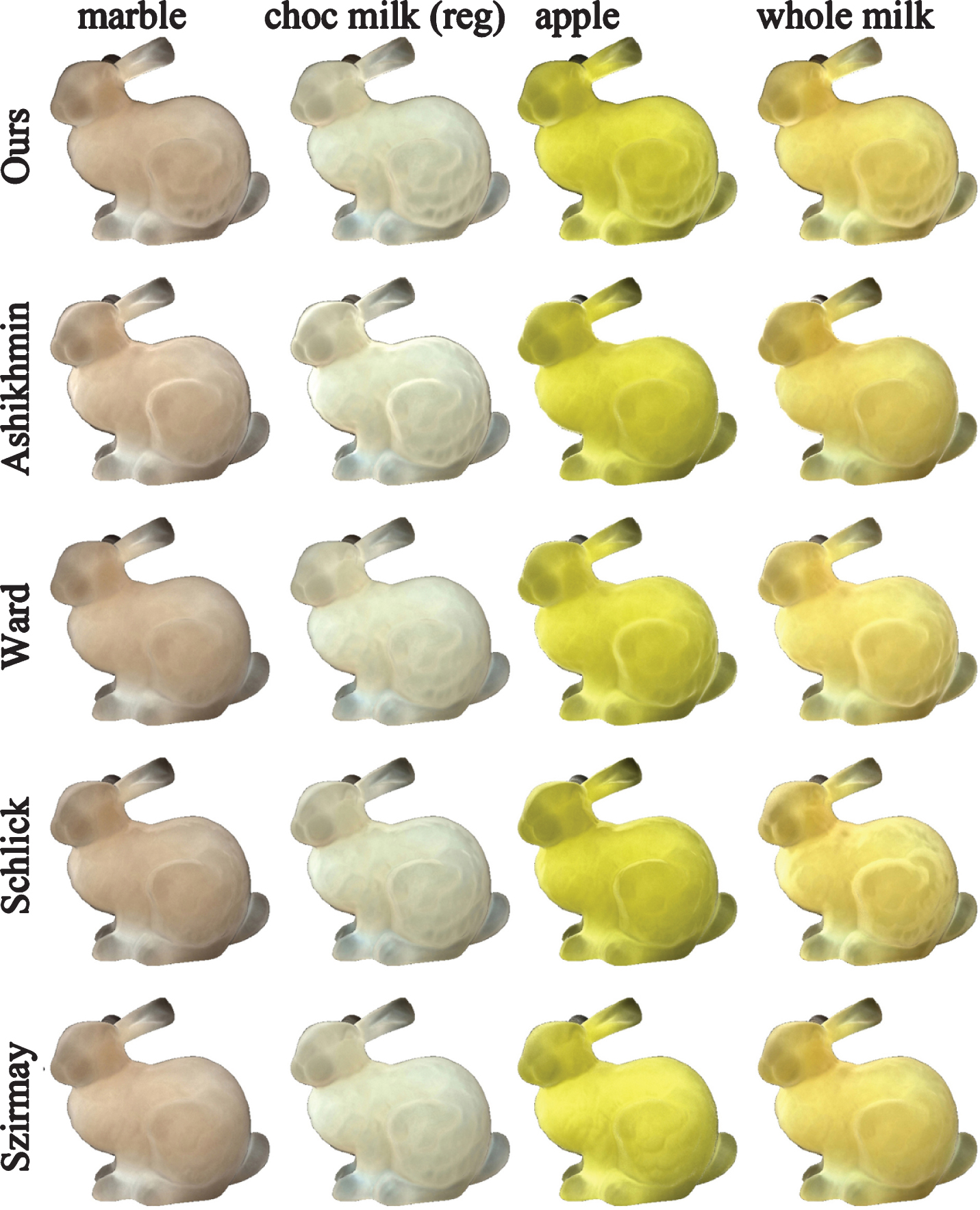
Bunny object rendered with the directional dipole model in combination with the highlight generation model’s highlight effects. Every row, from left to right, the materials are marble, chocolate milk (regular), apple, and whole milk. Every column, from top to botom, the highlight generation models are Our model, Ashikhmin model, Ward model, Schlick model, and Szirmay model.
The presented model is quantitatively analyzed and validated against a ground truth reference employing ray marching in the subsurface scattering process. We perform the following operation steps for ray marching inside the medium: (1) Sample the distance to the next scattering event. (2) If the scattering event is outside the medium, deposit the scattered ray for highlight calculation. Otherwise, (3) use a Russian roulette technique with the scattering albedo, and if the scattering albedo is below a random probability, the ray is absorbed. Otherwise, (4) proceed to scatter the ray. We set the origin of the scattered ray, employed the Henyey-Greenstein function to sample the direction of the scattered ray, and performed ray marching on the scattered ray. If the scattered ray does not hit the medium, proceed to step (1). Otherwise, deposit the scattered ray for highlight calculation.
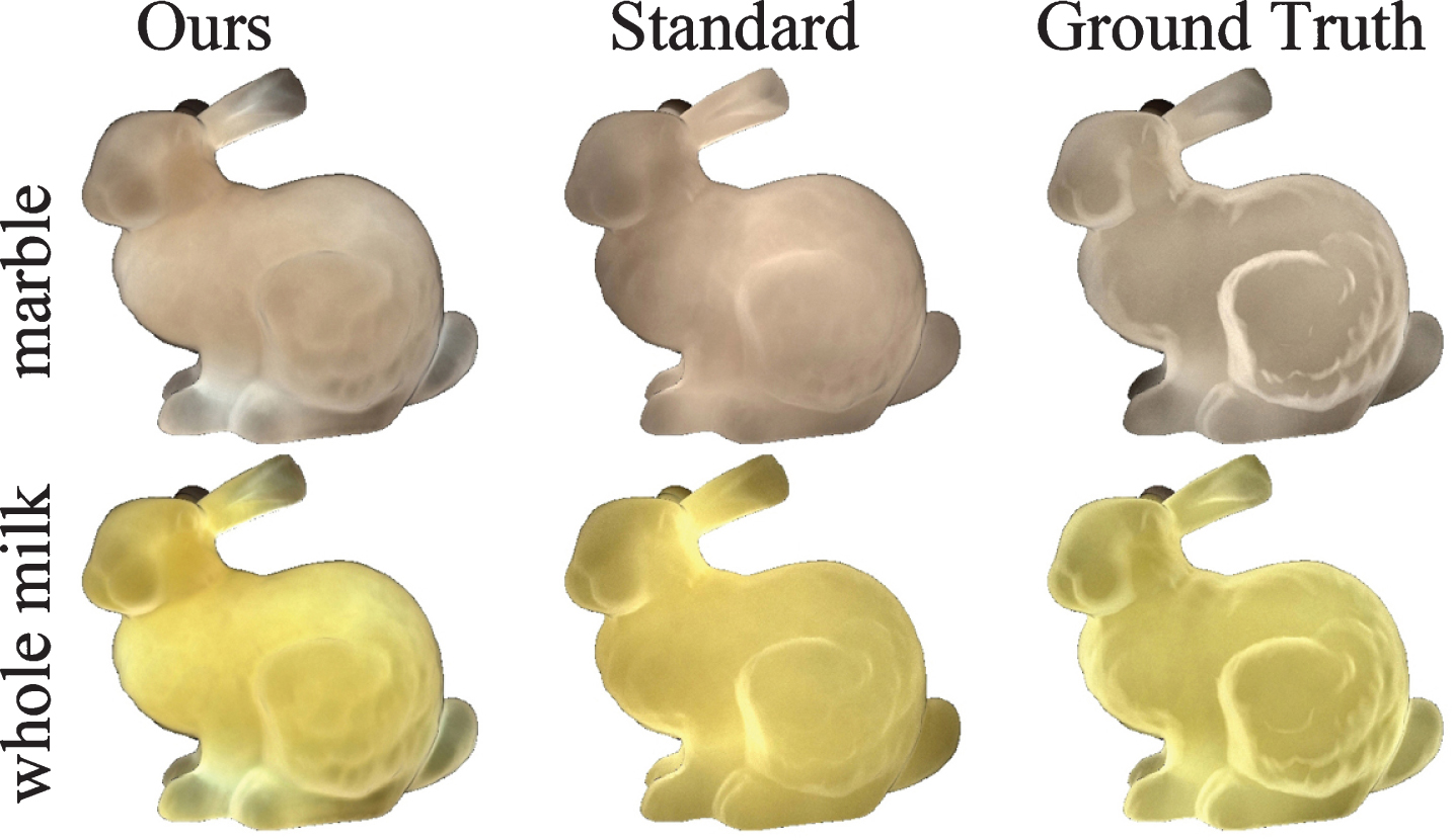
We apply the Torrance-Sparrow model to the subsurface highlights calculation because it is one of the most complete physical reflection models and has been validated by ray-marching-like simulation [30]. Configuring the presented model in a directional dipole instead of the traditional standard dipole for the two tested materials resulted in lower highlights RMSE (Root-Mean-Squared Error) compared with the ground truth. Specifically, the RMSE of highlights images for marble and whole milk configured in the directional dipole are 0.0146, 0.0161 (column 1 of Fig. 8), and the RMSE for the same two materials configured in the standard dipole are 0.0177, 0.0203 (column 2 of Fig. 8).

Comparison of the presented model (column 1) with the standard dipole configuration (column 2) and the ground truth reference (column 3) for different materials. Regions of row 2 are in the same positions of the frist and second columns of Fig. 5; and regions of row 4 are in the same positions of the third and fourth columns of Fig. 5 for corresponding materials.
Rendered images in combination with generated highlight effects for different materials.
For the marble material, the presented model has clear and smooth shape highlights in the bunny mouth region, while in the ground truth result, the highlight shape is more thicker in this region (see relevant images in row 2 of Fig. 7). In the result for the standard dipole, the highlight shape is clear with lower intensity than ours in the same region. In the left bunny face region, the presented model has weak and smooth highlights, while in the ground truth result, the highlight intensity is strong; in the result for the standard dipole, the highlights are weak and uneven over this region. As mentioned in the work of Bei Xiao et al. [31], geometric smoothness affects perceived translucency in a way that makes observers perceive smoothed objects as more translucent than objects with sharper geometries across various edge heights and illumination directions. Therefore, the highlights generated by the presented model have the potential to be treated as a cue for translucency perception in the less translucent roughness regions, such as the bunny mouth region.
For the whole milk material, we investigated the bunny leg region (see relevant images in row 4 of Fig. 7). For the presented model, the standard dipole configuration, and the ground truth reference, the generated highlights are all clear on the edge regions of the bunny leg, where the left and upper edge contours of the leg are enhanced and the local details of the right-side leg region are also preserved. For the presented model, the average highlight intensity is lower than that of the ground truth.
A new highlight generation model for the translucent materials is presented. The model can be easily integrated with a Monte Carlo ray tracer. It employs a directional diople model to generate the highlight effects while taking into account the directional subsurface light scattering. On the other hand, the existing highlight generation models only consider the incident light and the emergent light at the same surface point. Our model can produce the highlight effects on smooth and rough areas, as well as boudnaries and edges. Furthermore, the resulting rendered images faithfully reproduce a reasonable appearance of highlights in their positions and areas of coverage, and the visual appearance of boundaries and edges are more evident with the highlight effects. The number and the strength of highlight pixels are evaluated. Moreover, how the generated highlight effects of the presented model could increase the perceptual translucency appearance of edge areas of local regions is demonstrated by ccomparison with the ground truth reference.
Footnotes
Acknowledgments
This work was supported by the [National Natural Science Foundation of China] under Grant [81960327, 61563035].