
Abstract
At present, the UAV swarm positioning solution has the problems of poor positioning accuracy and instability. Therefore, it is necessary to design a sliding mode formation controller to realize formation. This study analyzes the self-service control strategy of the UAV swarm and establishes the behavior-based formation control strategy as the main research point of this article. This paper combines the Internet of Things and artificial intelligence algorithms to build an autonomous control model for the UAV swarm and designs the UAV formation control law from the disturbed and undisturbed conditions respectively. With reference to the basic architecture of the Internet of Things, this study imitates ZigBee’s self-organizing network to propose an adaptive networking scheme based on the Internet of Things by using the AP+STA working mode of the Internet of Things module in the node device. The results of the experiment show that the positioning accuracy of the UAV is high, which can meet the needs of cluster flight. Based on the Z-axis coordinates of the UAV, the accuracy of the laser distance measurement and the barometer value is significantly improved, the root mean square error is reduced, and the positioning result is significantly better than the data of direct traditional positioning.
Introduction
The full name of a UAV is called an unmanned aerial vehicle, which is a flying robot [1]. With the development of science and technology, UAV technology is also being updated. Microelectronic technology makes the accuracy of UAV higher and higher, and computer technology and artificial intelligence make UAVs more intelligent. The introduction of Chinese Industry 4.0 and Made in China 2025 has accelerated the rapid development of the UAV industry. At present, the common unmanned aerial vehicles on the market are fixed-wing and rotor-type, of which the rotor type is divided into single-rotor, three-rotor, four-rotor, six-rotor, and eight-rotor. The fixed-wing UAV has strong endurance and is suitable for long-time flight. Rotary-wing UAVs are flexible and convenient to control and can capture shots with fixed rotation and hovering in all directions without dead angles. However, the endurance and load are poor, and the lighter body is also easy to receive interference from the external environment. Among them, the four-rotor UAV is the most common, which has stable structure, flexible control, high safety performance, and low price, and can be arbitrarily flipped and controlled in multiple attitudes [2]. Four-rotor UAVs have been introduced by many industries. Basically, it can be seen in every industry, and it has brought many conveniences to our work and life. Among them, UAVs are mainly used for reconnaissance, surveillance, and target shooting in the military field. In the 1980 s, the United States used UAVs to fight against the outside world, which not only reduced casualties, but also locked and monitored the enemy. In the field of civil and commercial applications, the UAV scans and inspects high-voltage transmission lines in all directions by loading high-definition cameras and infrared detection devices. In the future, it will also be equipped with special devices such as robotic arms to replace damaged or aging devices and remove floating objects from high-voltage lines.
The single UAV has the advantages of high flexibility and strong maneuverability when performing tasks. However, due to the short lifespan of the single UAV, the limited equipment carried, and the limited monitoring range, the single UAV has the problems of small coverage, low efficiency, and insufficient monitoring when performing tasks. Moreover, once a failure occurs, it is difficult for the single UAV to successfully complete its mission. Facing the increasingly complex application environment and the development of UAV technology, the method of multi-UAV collaborative flight to complete the task came into being. The multi-UAV cooperative control system is that multiple UAVs are arranged according to a certain formation and ensure that the formation stability can be maintained during the flight process, and the task can be completed in cooperation. The advantages of the multi-UAV system are mainly manifested in it can carry more sensors and other equipment, can work in different places at the same time, at the same time obtain a larger and more accurate amount of information, and provide a more accurate decision basis. Multi-UAV systems have redundant resources and are more robust and fault tolerant. When a single UAV in the formation fails, it will not cause the entire formation system to crash or fail the mission, thereby making up for the lack of a single UAV. When the multi-UAV system performs an attack task, it can simultaneously strike the target from multiple angles, improve the hit rate, shorten the task time, and avoid the enemy’s counterattack in a short time [3]. The multi-UAV cooperative control system is not simply a combination of multiple UAVs, which involves many subject knowledges: information fusion technology, formation control technology, formation design, communication networking technology, etc. With the increase in the number of UAVs in multi-UAV systems, the model of the entire system is more complex, the communication volume is larger, and the problem of collision prevention between UAVs is also more difficult to solve. Therefore, how to design a reasonable and reliable collaborative control method and put it into practical application has important research significance [4].
Related works
Information perception and obstacle avoidance technology means that the UAV uses airborne detection sensors to sense the flight environment, and the system controller sends control signals according to the sensor data to prevent collisions. At present, researchers from various countries have made great progress in perception and obstacle avoidance algorithms. The literature [5] added perception and obstacle avoidance algorithms to the designed hybrid controller and verified the effectiveness of the method on the UAV semi-physical simulation platform and found that it can avoid obstacles accurately. The literature [6] used the received signal strength (RSS) of the airborne communication module to estimate the distance between UAVs and compare it with the set safety distance. If other UAVs invade the safe area, an obstacle avoidance warning will occur, and the trajectory will be re-planned according to the obstacle avoidance algorithm, which solves the problem of UAV positioning and obstacle avoidance in the field search scenario. The literature [7] proposed the design and implementation of a sampling-based UAV obstacle avoidance path planning method and used a closed-loop fast search random tree algorithm to design a trajectory tracking controller. This method can find a feasible path solution in a short time to avoid collision with other aircraft or moving obstacles. Finally, this literature used two Parrot AR-UAVs to verify the method. UAVs will have communication failures, actuator failures, etc. during the execution of tasks. Fault-tolerant control means that when a system fails, it can take corresponding measures to maintain its original performance or remain within an acceptable range. According to the type of fault, two types of methods, passive fault tolerance and active fault tolerance control, can be designed. Passive fault-tolerant control mainly uses the fault information to determine the control compensation amount, and the normal system state and fault state must be considered when designing the controller. The main method of active fault-tolerant control is to rebuild the controller. The literature [8] summarized the development of UAV fault diagnosis and fault-tolerant control. The literature [9] designed a fault diagnosis mechanism using a nonlinear fault detection observer, and then designed a fault-tolerant control mechanism based on the dynamic surface control method and compensation controller, thereby ensuring the stability of the faulty system. In the literature [10], the quaternion is used to construct the attitude dynamics of the UAV to avoid the singular problem, and the nonlinear adaptive observer is designed for the partial failure of the quadrotor UAV actuator. Moreover, this document combines a sliding mode controller to design a fault-tolerant control mechanism to ensure the stability of the UAV attitude system and verifies the effectiveness of the method on the HILS test platform. The fault-tolerant control in a limited time can ensure that the faulty system can recover to a stable state in a short time. Since the UAV system may crash in a short time after a failure, the fault-tolerant control in a limited time is very important. Sliding mode variable structure control method (SMC) is widely used because of its robustness to uncertainties and disturbances of nonlinear systems and low sensitivity to system parameters. The literature [11] studied the multi-UAV fault-tolerant cooperative control technology based on sliding mode control. Based on the control idea of the inner and outer loops, the outer loop generates feasible control instructions, and the inner loop performs fault-tolerant control to offset the adverse effects of actuator failures on the UAV system, which guarantees the limited time stability of the faulty UAV and keeps the formation unchanged. The literature [12] proposed a rigid robot control method based on terminal sliding mode control (TSMC). Compared with the traditional sliding mode control method, TSMC can ensure that the tracking error of the robot system converges to zero within a limited time. The literature [13] designed a fault-tolerant control mechanism for underwater vehicles based on the adaptive terminal sliding mode control method. The literature [14] studied the trajectory control of aircraft with modeling uncertainty, external interference and multiple faults. Moreover, this literature used two adaptive algorithms to estimate unknown fault information and system disturbance information, and designed a fault-tolerant control method based on fast terminal sliding mode control (FTSMC), which ensures that the aircraft can converge to an equilibrium state within a limited time after an actuator fault occurs. The literature [15] studied fault-tolerant control mechanisms based on non-singular terminal sliding mode control (NTSMC) and non-singular fast terminal sliding mode control (NFTSMC). It is proved that NTSMC and NFTSMC have a faster convergence speed and avoid singular problems than traditional sliding mode control methods, and NFTSMC has a faster convergence speed than NTSMC.
In the multi-UAVs cooperative control system, how to realize multi-UAVs cooperative flight is a major research difficulty. The goal of collaborative control is to make the system achieve a specific formation by adjusting the flight trajectory of each UAV. Multi-UAV cooperative control system is divided into centralized control system and distributed control system [16]. The centralized control system refers to the existence of a control center to realize the control of the entire multi-UAV system, to achieve signal communication and formation control, which is similar to the role of the human “brain”. This control center can be a ground station, a sea-based platform or an air early warning aircraft, or it can be another manned aircraft, or it can be a UAV with more complete functions. All unmanned aerial vehicles send their detected information and their own flight status information to the control center. Then, the control center analyzes, merges, and makes decisions to send the new control information to each UAV in the collaborative system. After that, the unmanned aerial vehicles in the collaborative system complete the tasks assigned by the control center through their own controllers [17]. The article [28] focuses on IoT and its major role in sophisticating the human behaviours and efforts. This paper also dealt with the collection of various data from various resources that are connected to the internet. The literature [29] talks about the various problems in the vehicular communication field with the proposal of cooperative centralized and distributed spectrum sensing model. Due to the implementation of cooperative cognitive model, interference and various hidden problems are minimized. The literature [30] addresses the problem such as massive volume of bigdata and come up with the concept of SmartBuddy to make intelligent and smart environment using human behaviours and human dynamics. The literature [31] talks about the construction of directed acyclic graph for video coding algorithms for motion estimation in parallel reconfigurable computing systems. Also, partitioning algorithm plays a major role to speed up the video processing. The article [32] dealt exploiting IoT and BigData Analytics using Hadoop ecosystem in real time environments. Implementation of IoT-based Smart City is achieved by the above-mentioned processes [33, 34].
Multi-UAV formation fault tolerance control based on fault hiding method
The formation flying of UAVs is widely used in real life, but the occurrence of a failure often affects the entire formation. The failures of UAVs generally include actuator failures and sensor failures. Generally, the method of providing physical redundancy by using redundant devices and the method of fault tolerance control (FTC) can be used to solve these fault problems. The method of fault tolerance control (FTC) can be divided into active and passive fault tolerance. The passive faulttolerant method achieves the purpose of fault-tolerance by designing a robust and insensitive controller. The active fault tolerance can be divided into methods with fault detection isolation and identification (FDII) modules and those without FDI modules such as adaptive control methods. It achieves the purpose of fault tolerance by readjusting the controller parameters or structure[18].
The active fault-tolerant control method based on the principle of fault hiding is to hide the fault by inserting the reconstruction module between the faulty device and the nominal actuator. It does not require readjustment and reconstruction of the nominal controller, and better retains the accumulated experience and knowledge of the nominal controller. If the module after reconstruction has the same output as the normal system before failure and the reconstructed system is stable, the reconstructed system is considered to be effective.
The gravity of the quadrotor UAV is expressed as F
g
= [0 0 mg]
T
in the earth system, The expression converted into the machine system is [19]:
The expression of propeller lift under the mechanical system is:
In the formula, K T is the lift coefficient and Ω is the speed of the four propellers.
The torque model of the four-rotor can be simplified into two kinds of propeller’s rotating moment and gyroscopic moment. The four-rotor propeller’s rotating moment can be expressed as:
Among them,
In order to facilitate the establishment of a state space model, the input u i = [M φ M θ M ψ ] T is reselected, and its physical meaning is an approximation of the three-axis external moment.
Among them:
Among them, T is the lift force of the four axes, Ω is the rotation speed of the four axis propeller, and Q is the rotation torque of the propeller.
The model of the quadcopter UAV can be expressed in the following state space form:
Among them, the state vector X
i
(t) = [x
i
y
i
Among them:
The UAV formation uses a master-slave formation model, where only two-dimensional horizontal formation control is considered. The formation control model expression is as follows [21]:
Among them, (X F , X L ) is the position of the slave UAV, (Y F , Y L ) is the position of the master UAV, and ψ L is the yaw angle of the master UAV, as shown in Fig. 1.
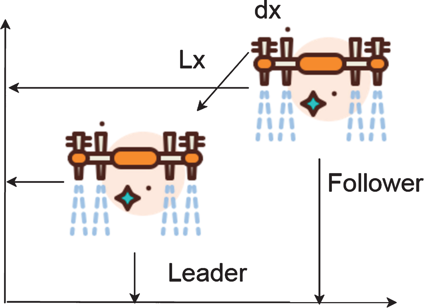
UAV horizontal formation diagram.
The derivative of the distance between the master and slave UAVs can be obtained as:
We define e
x
, e
y
, e
ψ
as the error between the expected value and the actual value, where
Then, the error equation that can be obtained is:
Among them, v lx v fx , v ly , v fy represents the speed of the master in the x-axis direction, the speed of the slave in the x-axis direction, the speed of the master in the y-axis direction, and the speed of the slave in the y-axis direction, respectively [22].
The error formation dynamics equations of the UAV have been described above. Here, this study designs a sliding mode formation controller to achieve formation. Moreover, this study designs the UAV formation control law from the disturbance situation and the disturbance-free situation [23].
The error equation of the UAV can be written as follows:
The formation error equation is written as follows:
Among them:
The sliding mode surface is defined as:
Among them, k is the system parameter matrix.
By differentiating the sliding mode surface, the following results can be obtained:
The sliding mode control law is designed as follows:
The Lyapunov function is designed as:
The Lyapunov function is derived:
When we design L greater than 0, then
The following is the design of the formation controller under the disturbance.
In the case of disturbance, the formation error equation can be written as:
Among them, F is the uncertainty:
Similarly, the sliding mode surface is defined as:
By differentiating the sliding mode surface, the following results can be obtained:
The Lyapunov function is designed as:
By differentiating the Lyapunov function, the following results can be obtained [25]:
The sliding mode controller is designed as:
Then the derivative of the Lyapunov function can be written as:
The designed control law can make the system stable. However, in the real control system, the upper bound of the uncertainty of F is unknown, and it is difficult to estimate. However, the upper bound
Among them,
By differentiating the Lyapunov function, the following results can be obtained:
The sliding mode controller is designed as:
The adaptive rate
Similarly, the derivative of Lyapunov function can be rewritten as:
When we design L greater than 0, then
The Internet of Things technology is currently the most widely used wireless communication technology. Most public places are equipped with wireless APs, which can be used only by purchasing devices and connecting to the Internet of Things network. The components are cheap, stable, and have a long communication distance. The disadvantage is that the power consumption is large, the devices that can be connected are limited, and the number of nodes usually does not exceed 50. The system considers multiple factors such as communication distance, communication rate, node layout density, node device price, and system safety and reliability. Finally, the Internet of Things technology is selected as the communication processing solution of the aircraft group system.
Referring to the basic architecture of the Internet of Things, this paper imitates ZigBee’s self-organizing network mode to use the AP+STA working mode of the Internet of Things module in the node device and proposes an adaptive networking scheme based on the Internet of Things. This solution can achieve the self-organization of each UAV node, and various information between nodes can be converted automatically and transmitted to the control agency in time. The network topology is shown in Fig. 2.
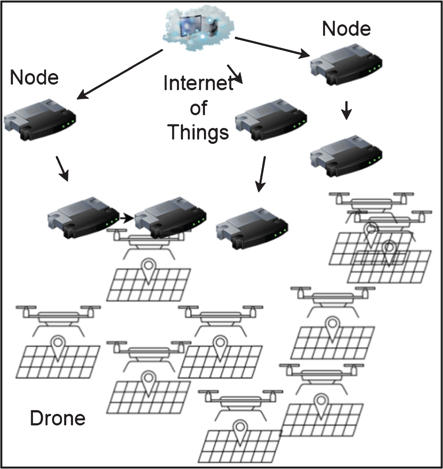
Internet topology diagram of Internet of Things.
In the picture, the router can be an ordinary wireless router placed in the center of the room, or a hotspot route built by the UAV. Each micro four-rotor UAV node connects to the router or nearby nodes through a security password set in advance.
The type of packet determines its transmission direction in the node network after networking, and it is detected that the network packet is transmitted from each node and transmitted to the server step by step. The node control commands or parameter setting commands transmitted by the server are transmitted to each node in the reverse direction one by one, and the node determines whether the message is transmitted to itself according to the node number in the message. The different types of message transmission formats are shown in Fig. 3.
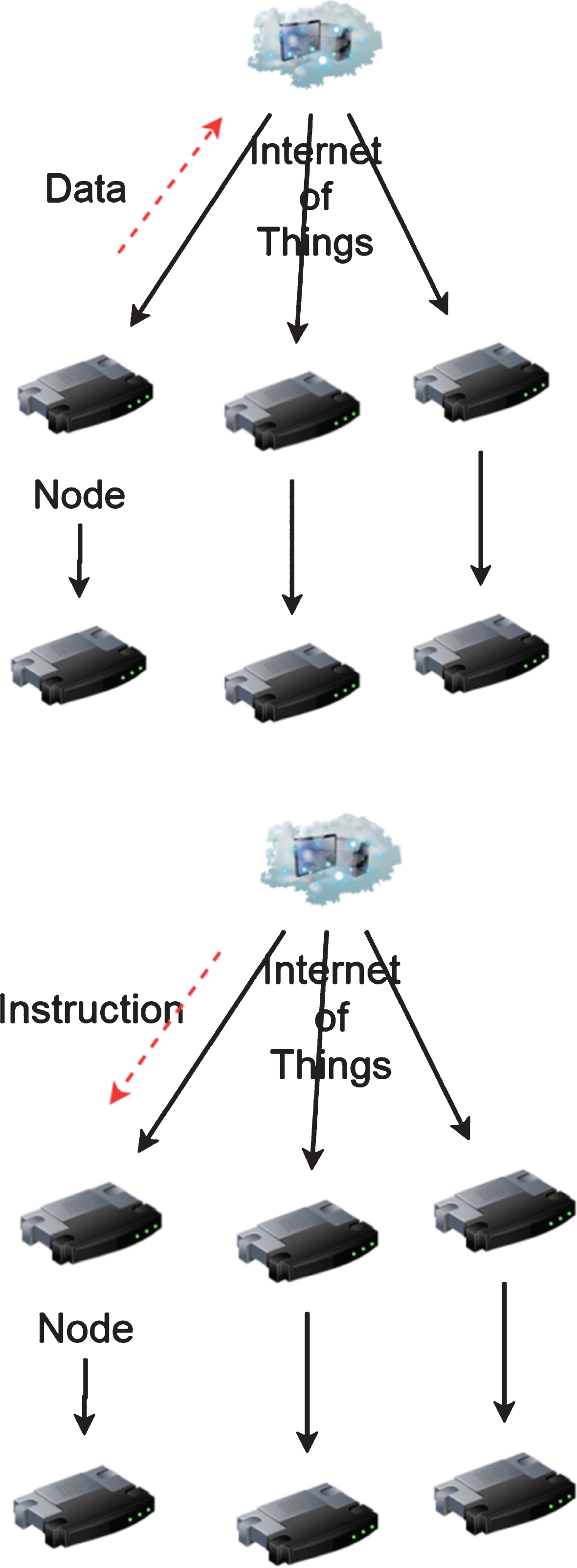
Message delivery method.
After that, the UAV is assembled into the network, as shown in Fig. 4.
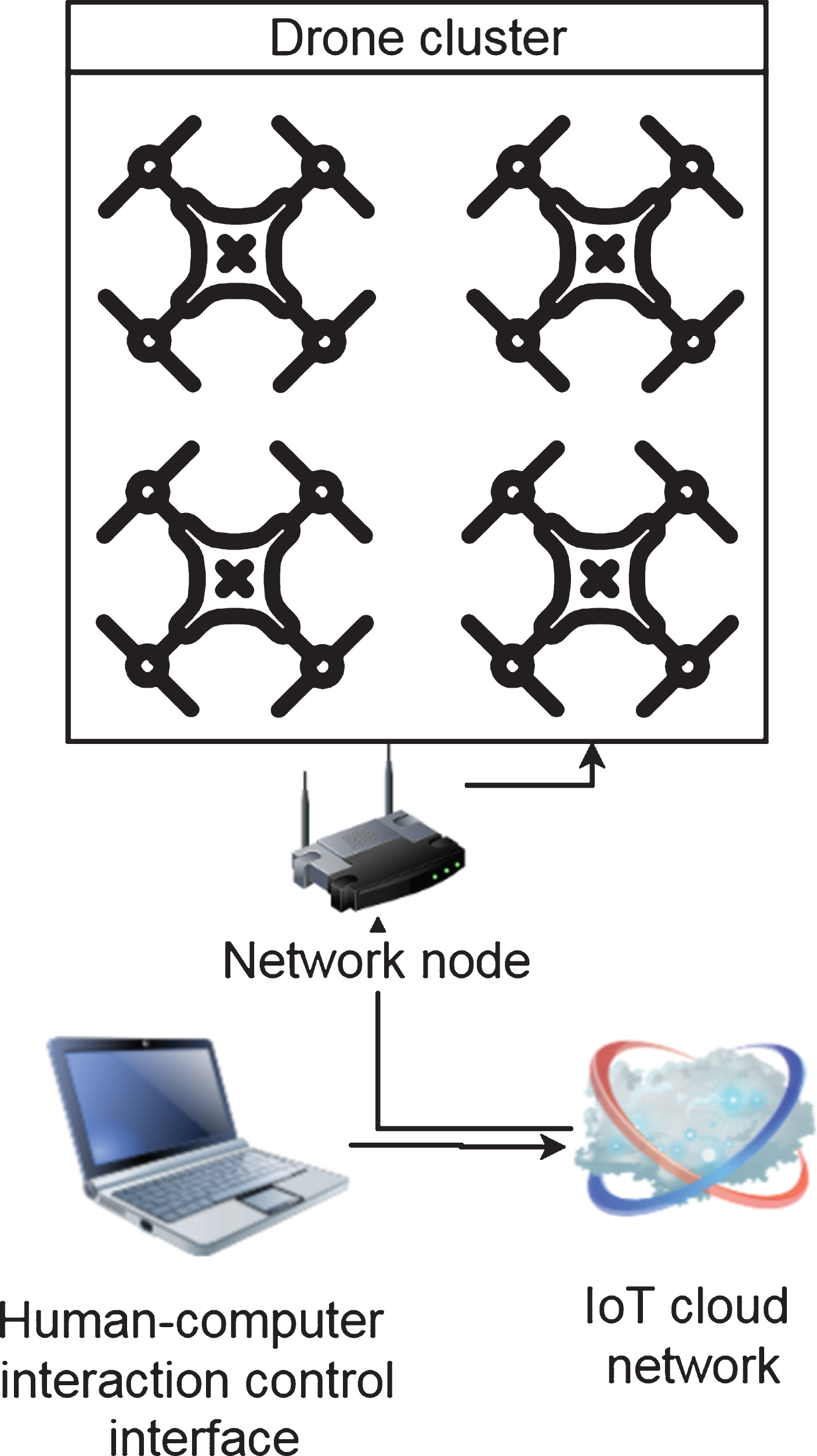
Network test system diagram.
In the currently used flight modes, according to the difference in the position of the aircraft head, the four-rotor UAV can be divided into “+mode” and “×mode”. The “+mode” aircraft head is on a certain motor, while the “×mode” aircraft head is between two motors. When “+” and “×” are facing the nose direction, the appearance of the UAV is shown in Fig. 5.
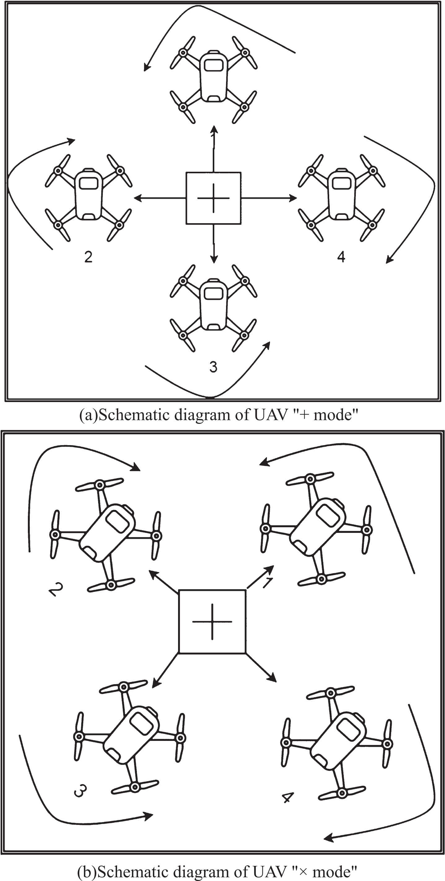
UAV flight mode.
The design of “+mode” system is simple, but the action is not flexible enough. The design of the “×mode” system is complex, but the action is more flexible. The operating principles of these two types of modes are the same. Next, we will focus on the overview of the control mechanism under the “×type” mode. The external environmental influences, such as the influence of external forces such as wind force, are not considered here, and the ground surface is assumed to be a standard plane.
The basic principle of the four-axis aircraft is to control the four motors to drive the blades to generate lift through flight control and control each motor and blade to generate different lifts to control the attitude and position of the aircraft. Four axes can realize four kinds of movement in the air, namely vertical movement (vertical ascent and vertical descent), pitch movement (forward and backward movement), roll movement (left and backward movement), and yaw movement (clockwise and counterclockwise movement).
Vertical movement is relatively simple compared to other movement methods. Because there are two sets of motors rotating in opposite directions, they can counteract their reverse torsional moments to the aircraft. When the rotating power of four motors is increased at the same time, the speed of the four rotors is increased to increase the overall lift of the UAV. When the overall lift is sufficient to support the weight of the UAV, the four-rotor UAV can be raised vertically. If the rotation power of the four motors is reduced at the same time, the rotation speed of the four rotors decreases and the overall lift of the UAV decreases. When the overall lift is less than the weight of the UAV, the quadrotor will land vertically until it stabilizes on the ground, so the UAV can move vertically along the Z axis of the three-dimensional space. When the amount of external disturbance is zero, when the lift formed by the four rotors is the same as the weight of the UAV itself, the four-rotor UAV can maintain hover or move at a constant speed. Therefore, ensuring that the rotation speed of the four rotors increases or decreases simultaneously is the key to vertical movement.
The yaw movement of the four-rotor UAV can be completed by the reverse torsional torque formed by the rotor. Due to the air resistance, the rotor of the UAV will produce a reverse torque relative to the direction of rotation. In order to eliminate the interference of the reverse torque, two of the four rotors can be rotated clockwise, and the other two can be rotated counterclockwise, and the rotation direction of each rotor in the diagonal is the same. The magnitude of the reverse torsion torque is related to the wing rotation speed. When the rotation speeds of the four motors are the same, the reverse torsion torques formed by the four rotors are balanced with each other, and the four-rotor UAV does not rotate. When the rotation speeds of the four motors are different, the unbalanced reverse torsion torque will cause the four-rotor UAV to rotate.
As a type of under-driving system, the four-rotor UAV controls and adjusts the rotation speed of 4 motors to complete various movements in 6 degrees of freedom in space. If we randomly combine the above movement methods, the UAV can also perform more complicated movements.
The UAV flight control circuit board is equipped with a microcontroller (MCU) and various sensor units. The sensors mainly include accelerometers, angular velocity meters, barometers and infrared lasers. These sensors provide acceleration information, angular velocity information and barometric altitude information when the aircraft is in flight. After the MCU collects sensor data and performs arithmetic operations, it can obtain the attitude angle and altitude information of the UAV. The flight control board is also equipped with a UWB module, which can measure the distance between the UAV and the surrounding base stations, and then solve the spatial three-dimensional coordinates of the UAV. There is also a WiFi communication module on the flight control board, which is used to receive the control commands of the remote controller. This type of data is then calculated by the control algorithm to obtain the control amounts of the four UAV motors. Finally, control signals are transmitted through the control pins on the circuit board to control the rotation speed of the UAV motor to ensure stable and controllable flight of the UAV. The hardware system block diagram is shown in Fig. 6.
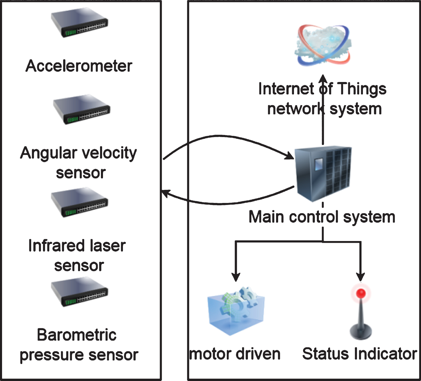
UAV hardware system block diagram.
The main controller MCU, as the control center of the UAV, plays a vital role in the stable flight of the UAV. It also assumes multiple responsibilities, including sensor data reading, data fusion, PID control, motor control, wireless communication, etc. Therefore, when selecting a model, there are many problems that need to be seriously considered. Here are a few of the most common problems:
Because the UAV is flying in the air, it is inconvenient to directly measure the real coordinates. Therefore, we hang a long line on the UAV, measure the length of the remaining long line on the ground, calculate the height of the UAV, that is, the z-axis coordinate value, and measure the x-axis and y-axis coordinate values according to the falling point of the vertical line. The positioning curves of real coordinates and estimated coordinates in 50 experiments are shown below. Figure 7 is the x-axis real coordinate and estimated coordinate curve, Fig. 8 is the y-axis real coordinate and estimated coordinate curve, Fig. 9 is the z-axis real coordinate and estimated coordinate curve, and Fig. 10 is the xyz error curve. The corresponding tables are shown in Tables 1–4.
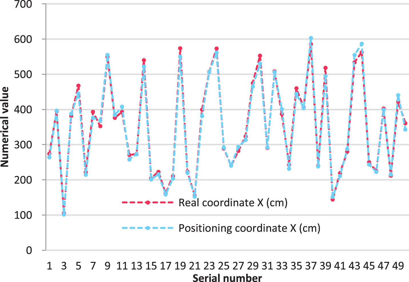
x-axis coordinate curve diagram.
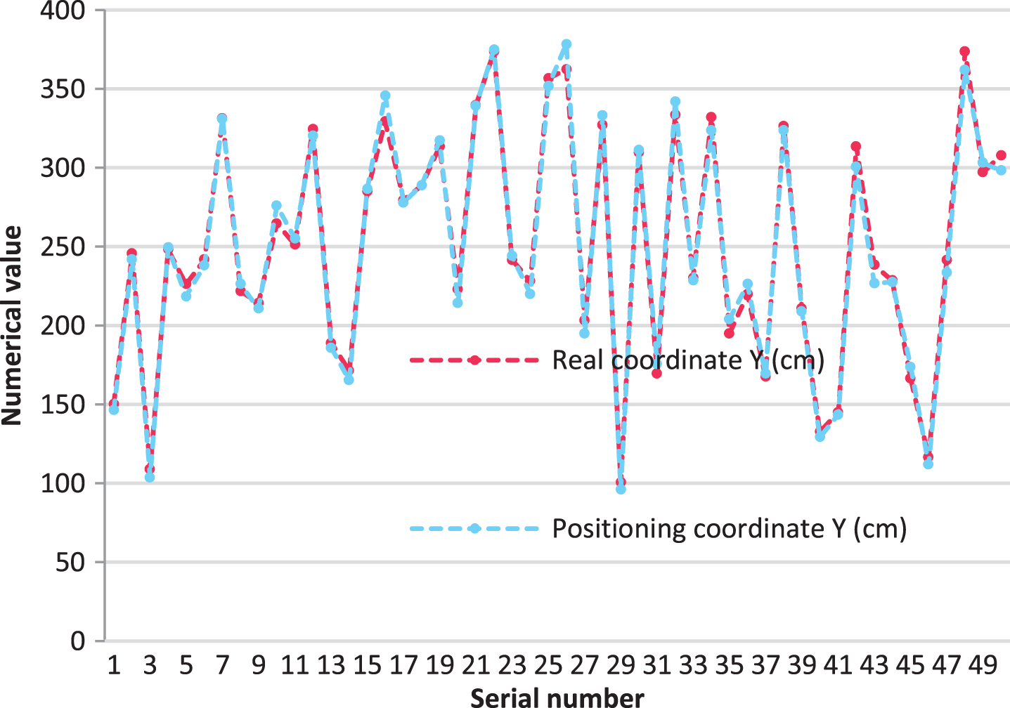
y-axis coordinate curve diagram.
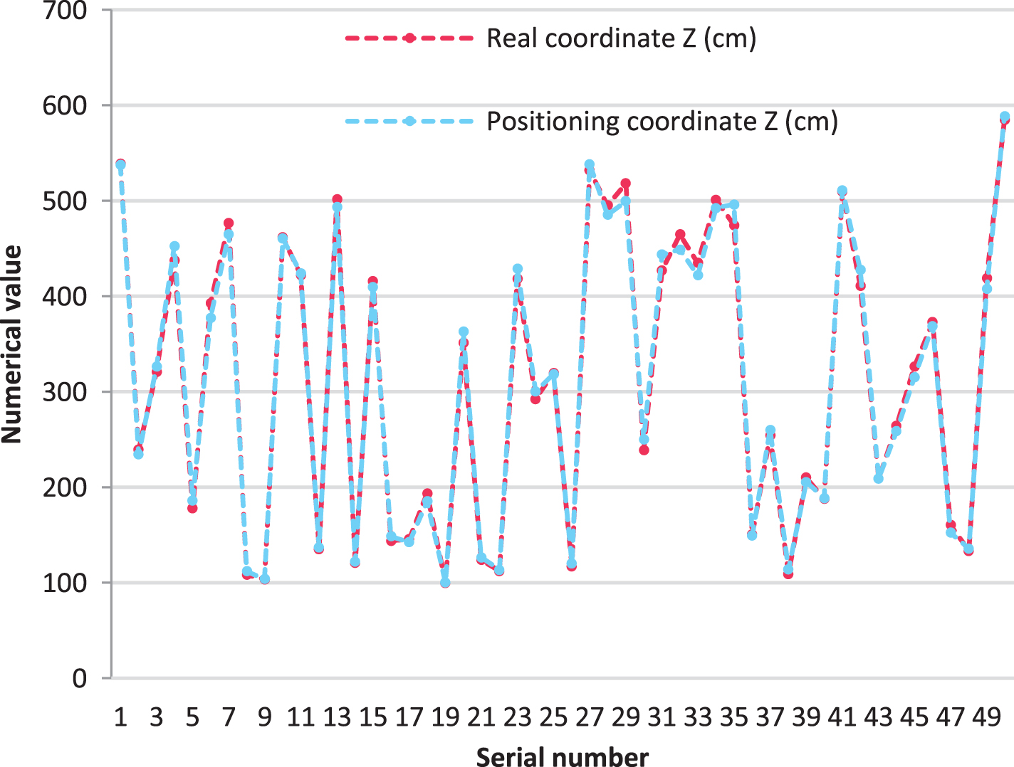
z-axis coordinate curve diagram.
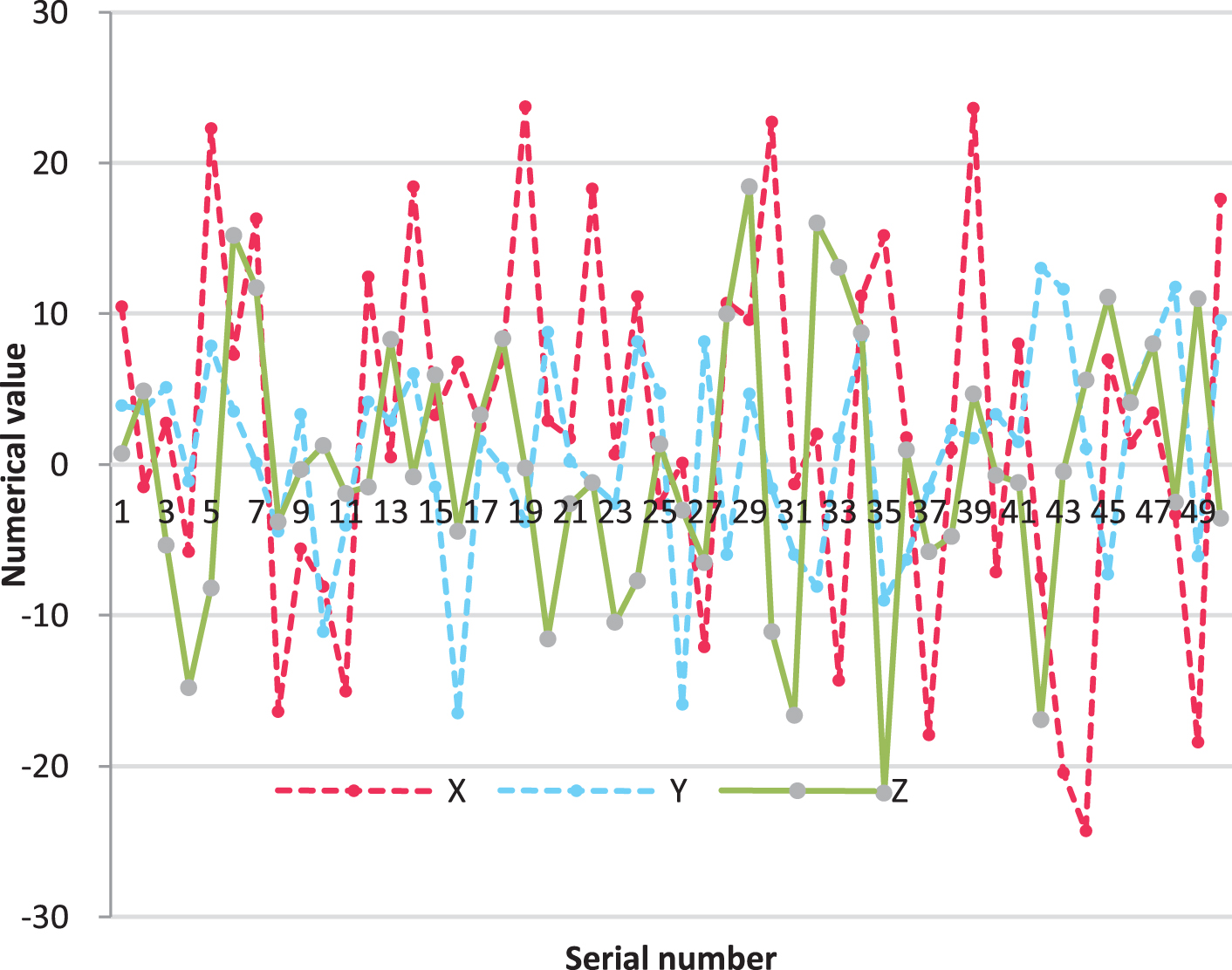
xyz error curve diagram.
Statistical table of x-axis coordinate curve
Statistical table of Y-axis coordinate curve
Statistical table of Z axis coordinate curve
Statistical table of xyz error curve
Experimental results show that the positioning accuracy of the UAV is high, which can meet the needs of cluster flight. Based on the Z-axis coordinates of the UAV, the accuracy of the laser distance measurement and the barometer value is significantly improved, the root mean square error is reduced, and the positioning result is significantly better than the data of direct traditional positioning.
This study analyzes the self-service control strategy of the UAV cluster and establishes the behavior-based formation control strategy as the main research point of this article. In this study, the UAV mass center motion model was established. On this basis, the UAV formation motion model was constructed by combining the pilot reference point method of formation maintenance. Moreover, this research studies the formation transformation method. In addition, in this study, the formation matrix representation method is used to represent the formation, and a formation library is constructed. The formation transformation evaluation system about environmental constraints and UAV cluster track constraints is established and the formation transformation evaluation function is constructed. At the same time, this research studies the behavior-based formation control algorithm. In order to improve the formation retention rate during the formation tracking task and save the time of formation transformation, the optimal strategy of the dynamic formation transformation of the drone under obstacle avoidance is considered in consideration of the obstacle avoidance situation of the drone cluster in the actual environment. Finally, based on the formation maintenance method referenced by pilots, this study designs the main behaviors in formation control and forms a formation control algorithm with multiple behaviors mutually restraining. Through experiments, the method proposed in this paper is applied to autonomous control of UAV swarm. The results show that the UAV positioning accuracy is high, which can meet the needs of cluster flight.
Footnotes
Acknowledgment
This paper was supported by the Fundamental Research Funds for the Central Universities, Research on multi-mode detection and intelligent decision technology for anti-UAV swarm system, NO. NZ2019008.