
Abstract
The most installed Renewable Energy Sources (RES) in micro-grids (MG) are Photovoltaic (PV) power and wind power. Due to the intermittent behaviour of renewable sources, parallel operation of RES and battery storage known as hybrid system is important particularly in remote micro-grids to reduce the fuel consumption by diesel generators and continuity of supply to the load. In this paper, multilevel inverter called Packed E-Cell (PEC) is used for parallel operation of RES and battery storage optimally for micro-grid applications. The PEC requires less components compared to other Multi-level inverters (MLI) topology with relatively low total harmonic distortion (THD). Further, selective harmonic technique based on optimization principle is used to enhance the harmonic profile using low frequency switching technique. The 3rd and 5th harmonics are eliminated using Genetic Algorithm (GA) optimization technique. The simulation-based analysis is done using Simulink/MATLAB and the results obtained for THD in the output current and voltage are presented and discussed in the paper. A comparative analysis is also presented with high frequency modulation technique phase disposition pulse width modulation (PDPWM) technique. The experimental validation of the proposed scheme is done using Typhoon HIL (hardware in loop).
Keywords
Introduction
The utilization of renewable resources in the energy system is increasing at an unprecedented pace. The main issues related to renewable energy are variability and uncertainty. To ensure reliable and economic operation of the system, proper management of different energy sources should be done. Generally, in micro-grid Photovoltaic power and wind power are used as energy source [1]. Since the system can’t be allowed to rely upon only on renewable sources, it is preferable that renewable sources are accompanied by appropriate storage units. This type of system is called hybrid energy source system. The hybrid energy source systems may be used for applications like remote micro-grids, rural applications, telecommunication, and stand-alone systems.
In the last few years, in depth research is done on the multilevel converter topologies due to several advantages associated with them for various applications [2]. The multilevel converters are not only able to produce an increased number of voltage levels but also capable of handling more power at medium voltages as the stress on the switches is less [3]. Some of the earliest multilevel inverter topologies are Neutral point clamped (NPC), flying capacitor converter (FC), cascaded H-bridge converter (CHB) [4]. Many researchers are focusing to adopt techniques that increases the number of voltage levels and energy efficiency.
Researchers are focusing on various MLIs configuration for optimal component count, number of voltage level, DC link voltage balancing, etc. Among many multi-level inverters, Packed U-Cell (PUC) has compact structure, less component count, etc., compared to its other multi-level counterpart. PUC topology has the advantages of both CHB and FC topology [5] but it has issue of capacitor voltage regulation. In this paper, a multi-level inverter called PEC developed in year 2019 [6] is adopted for hybrid energy source applications. By horizontal extension in packed E-Cell (PEC), the number of components is reduced in this inverter. A comparison of component count of various multi-level inverters is shown in the Table 1.
Comparison of PEC MLI with conventional MLI
Comparison of PEC MLI with conventional MLI
In PEC, with the use of redundant switching states the capacitors voltages can be balanced. Hence, both DC-link capacitors can be simultaneously charged or discharged, and this ensure capacitor voltage regulation without need of any additional controller [6]. This important property of packed E-cell can be effectively utilized for hybrid energy source utilization for micro-grid application. Such adoption of PEC is not done till date as far as the authors knows. For hybrid energy source the shunted capacitors are replaced by batteries, both batteries can be simultaneously charged and discharged with the redundant switching states. The terminal voltages of the batteries would be one-fourth of the bus voltage. Hence, a battery of much lower rating compared to DC-link voltage can be used. In place of DC source, PV module is placed in the adopted topology of packed E-cell. The concept is depicted in the Fig. 1.

Hybrid energy source fed modified packed E cell.
The output of a power converter mainly depends on the control type of the switching operation [7]. The control algorithms are classified as low switching frequency (up to few hundred Hz’s) and high switching frequency (in kHz) [8]. Space vector modulation (SVM), selective harmonics mitigation (SHM) and selective harmonics elimination (SHE) are the low switching frequency modulation schemes. Due to less switching in a cycle, low switching frequency modulations techniques are preferred for high power applications. The selective harmonics elimination SHE is generally adopted as low switching frequency modulation technique for multi-level inverters The MLIs operated with SHE has waveform of better quality with switches of low rating [9].
The quality of synthesized waveform of inverter output is determined by the parameter of THD. To optimize THD the synthesis waveform is analysed by applying Fourier series. Fourier series analyses gives the actual harmonic amplitude equations of the waveform. These equations are composed of trigonometric functions which are difficult to solve by analytic solutions. Metaheuristic approaches are therefore used to solve these types of problems. In this paper, a search-based algorithm known as Genetic Algorithm (GA) is employed to find solutions. With the use of Genetic Algorithm guaranteed convergence are obtained if the objective function is properly selected. Harmonic Elimination can be obtained with the help of genetic algorithm by obtaining the optimum switching angles. This work discusses the operation of a PEC fed from hybrid sources; the harmonic elimination is achieved with the help of Genetic Algorithm.
Section 2 of the paper discusses the Hybrid Energy Source Combination. In section 3, Multi-level output using Packed E-Cell fed from Hybrid Energy Source Combination is obtained. Section 4 discusses the Genetic Algorithm technique. In Section 5 harmonic elimination technique of PEC is proposed using Genetic Algorithm. Analysis of the proposed scheme is done in MATLAB/Simulink environment in section 6. Hardware in loop implementation is presented in section 7. Finally, Section 8 concludes the paper.
Depletion of fossil fuels is becoming a major issue now a days. Further, the consumption of fossil fuel leads to the greenhouse effect. Large number of small and large renewable energy sources are being used to meet the increasing energy demand. The major challenge associated with the renewable energy resources is the reliability. Due to uncertainty of the availability of the renewable energy resources, a hybrid renewable energy system with battery storage systems is used. The hybrid energy systems are also used in rural areas for essential supplies as they offer better reliability with less cost [10].
Packed E cell topology fed from hybrid sources
The packed E cell (PEC-9) structure comprises six active bidirectional current devices T1, T2, T3, T4, T5 and T6; one PV Cell based DC source E, single four-quadrant switch T7 and to form a single phase 9 level converter topology, two batteries are also incorporated.
The inverter is structured on the basic concept of employing an E-Cell type of arrangement as illustrated in Fig. 2. The redundant switching states obtained in this topology can be effectively used to balance the voltages of both the batteries in charging as well as discharging mode, which is required to balance the secondary DC link to maintain the voltage at the dc link to the half of the applied voltage as it is required for the attainment of five levels at the output voltage. The packed E cell structure consists of six active bidirectional current devices T1, T2, T3, T4, T5 and T6; one PV Cell based DC source E, one four-quadrant switch S7 and two batteries to form single phase 5 level converter design.

Modified packed E Cell inverter.
The 4-quadrant kind of arrangement is done at the midway of two batteries and AC terminal points of the Inverter. In the packed E-Cell configuration, capacitors are arranged in a horizontal row to produce only one secondary DC link and to make the multi-output voltage levels terminals due to the four-quadrant switch which makes it possible to attain five, seven, nine and eleven-level at the output.
With the proper selection of switching sequences, each of B1, B2 battery voltages (V1, V2) is maintained to one-fourth of the voltage at the input (E) so that the PEC is able to generate five-level voltage waveform. The switches (T1, T4), (T2, T5) as well as (T3, T6, T7) are operating complementarily.
GA was introduced in by Henry Holland in the early 1960 s [11]. GA is inspired by natural genetic and selection of the fittest theory of Darwin. Initially, a population is created by randomly generating solutions in the search domain. After that new population is created by crossover mutation and survival operators.
The algorithm of GA is given below:
The flow-chart for the GA program is shown in Fig. 3.
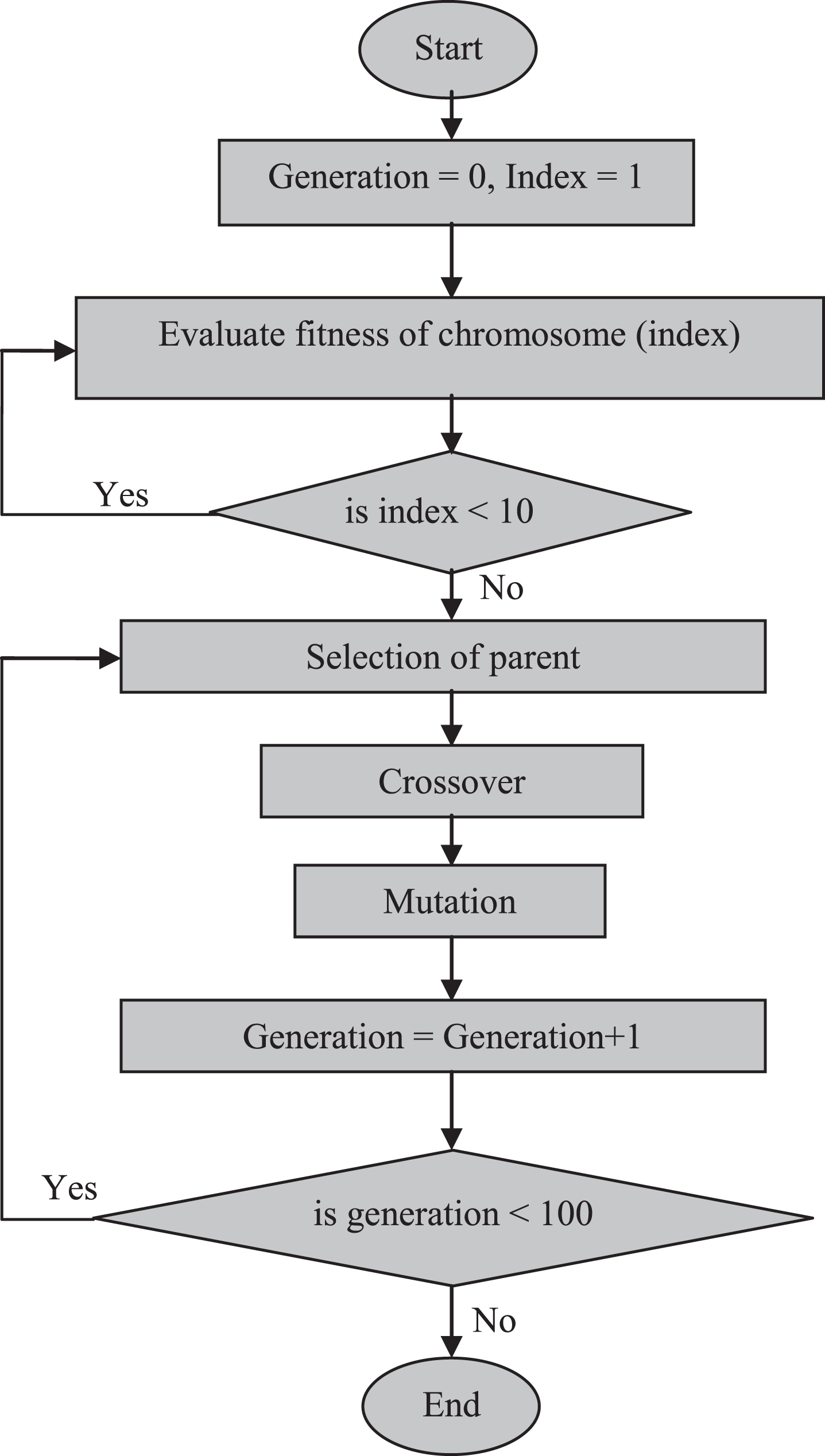
Flow-chart for the GA.
The quality of synthesized waveform of inverter output is determined by the parameter of THD. To optimize THD the synthesis waveform is analysed by applying Fourier series. Fourier series analyses gives the actual harmonic amplitude equations of the waveform. These equations are composed of trigonometric functions which are difficult to solve by conventional analytical solutions.
Any general periodic function in mathematical notation as follows can be written as:
Where a0, a
n
and b
n
are Fourier coefficients and ω is the fundamental frequency component. The Fourier coefficients are calculated as follows:
The output waveform has half wave as well as odd symmetry, we can conclude that, Fourier series output will contain only odd harmonic of sine terms. Harmonic amplitude equation of the proposed waveform is represented by Equation (3) & (4).
For the quarter wave symmetric output waveform the Fourier series coefficients are found as:
Where,
The Fourier coefficients are calculated in Equations (8)–(11).
If we consider equal magnitude or equal dc voltages, then these expressions are simplified as:
Therefore, the output can be written as:
The switching angles α
k
have to satisfy the following inequality constraint:
The expressions for fundamental component and harmonics components can be written as:
And for n th harmonics the voltage magnitude is:
For singles phase system having 5 switching angles, four low order harmonics can be eliminated along with fundamental voltage control. A number of methods have been used to compute switching angles and they are broadly classified as numerical techniques, Algebraic methods and optimization-based techniques. Equation (16) is implemented in GA to vary modulation index. GA is implemented for multi objective fitness function including equation (15) & (16). GA is initiated by randomly selected bit strings (chromosomes). These chromosomes are selected in domain of the switching pulse angles. Fitness is evaluated for each of the chromosome by applying chromosome solution to the objective function.
The chromosome returning the least value of fitness function is considered as fittest. Chromosomes are ranked accordingly to their fitness value. Next step in GA is selection which is chosen to be probability base (roulette wheel criteria) in this work. After selection new generation is created by operating crossover (mixing of chromosomes) and mutation (random modification of chromosome) operator to the selected chromosomes (parents).
The new generation is composed of elites (50%), elites are fittest chromosomes from previous generation. The rest population are created by crossover and mutation operator. The probability of application to parent chromosome of crossover operator is 80% and mutation operator is 10%. In this way a new generation is developed. The stopping criteria of GA is completion of 400 generation, fitness function, where fitness function is the function of harmonic amplitude of 3rd and 5th order harmonics.
The simulation is performed in MATLAB®/Simulink and important key results are captured and shown in Figs. 4, 5 and 6. Figure 4 shows the gating pulses for three switches. Figure 5 shows the output voltage across the load. The load current is shown in Fig. 6. To evaluate comparative performance of the technique phase disposition pulse width modulation (PDPWM) without GA have been applied in this work for packed E-Cell inverter. The specifications for the simulation analysis are presented in Table 2.

Gate pulses for three switches.
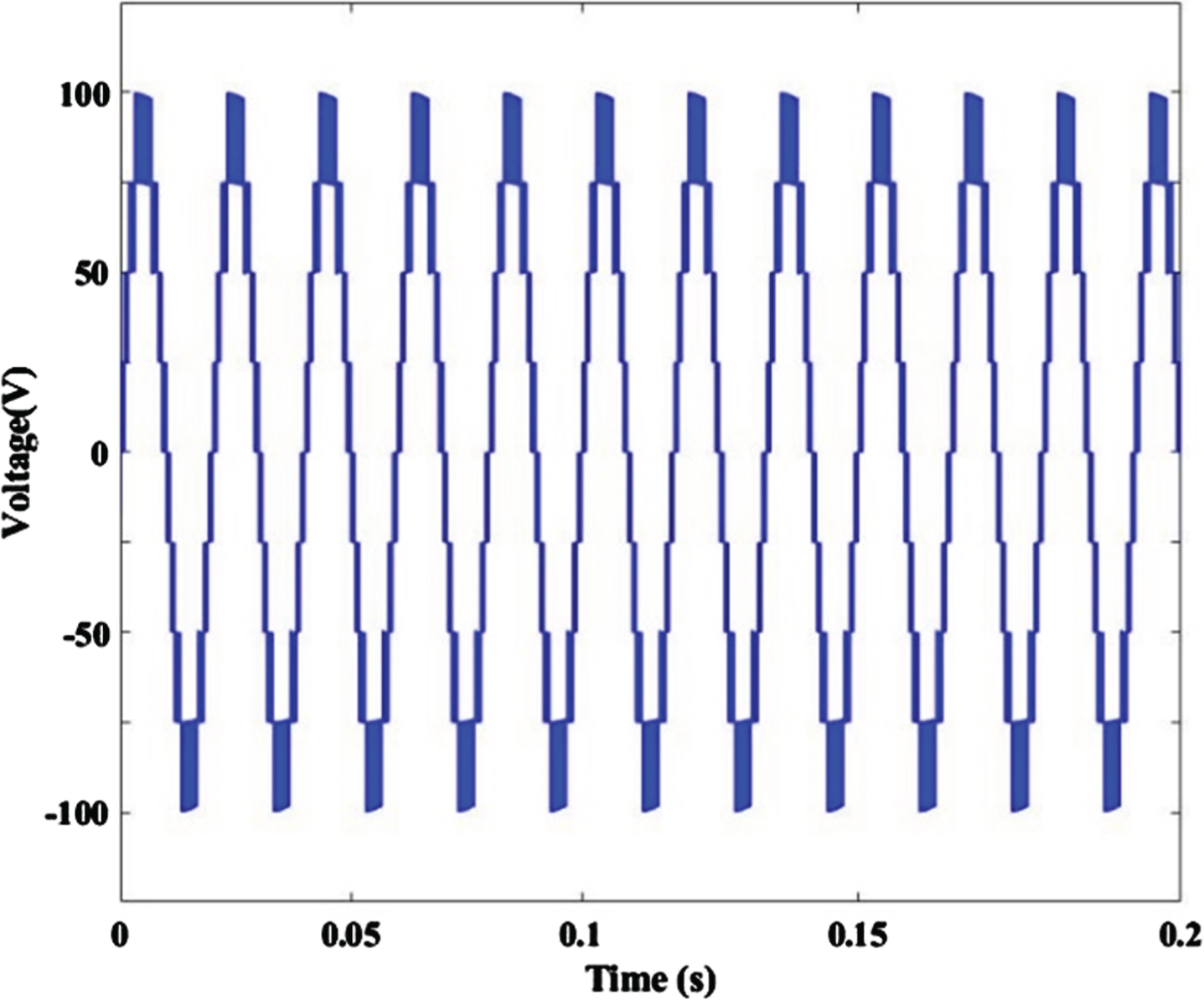
Output voltage across the load.
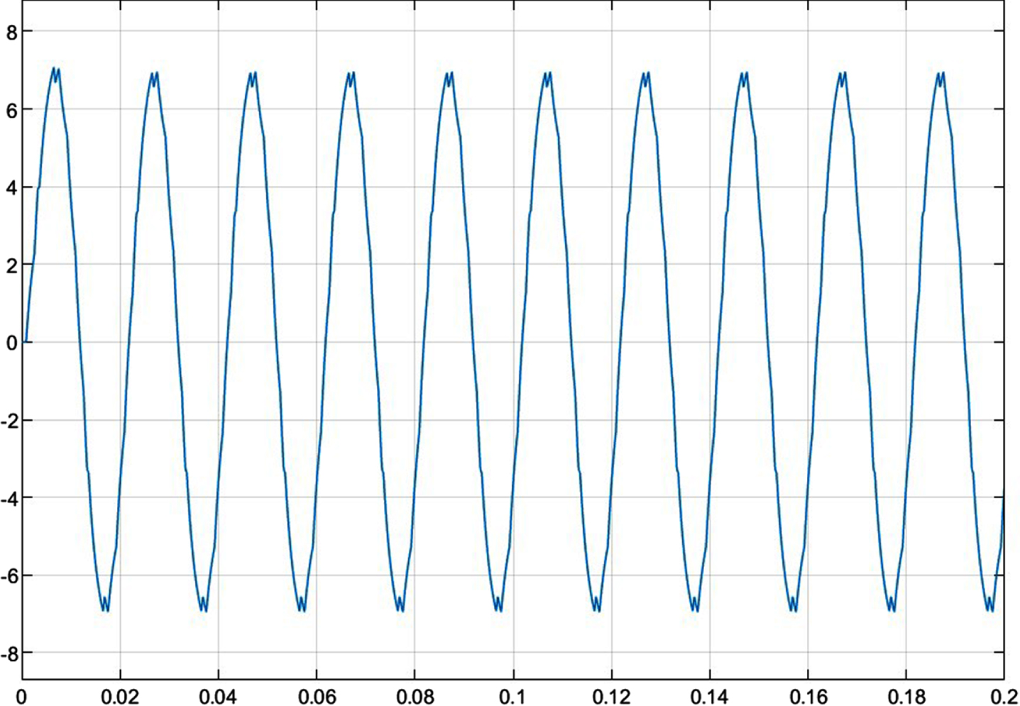
Load current.
Packed E cell circuit parameters
Comparison of Harmonics with different schemes
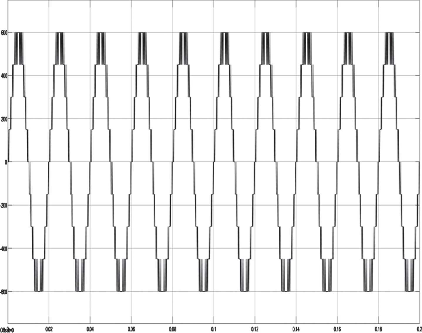
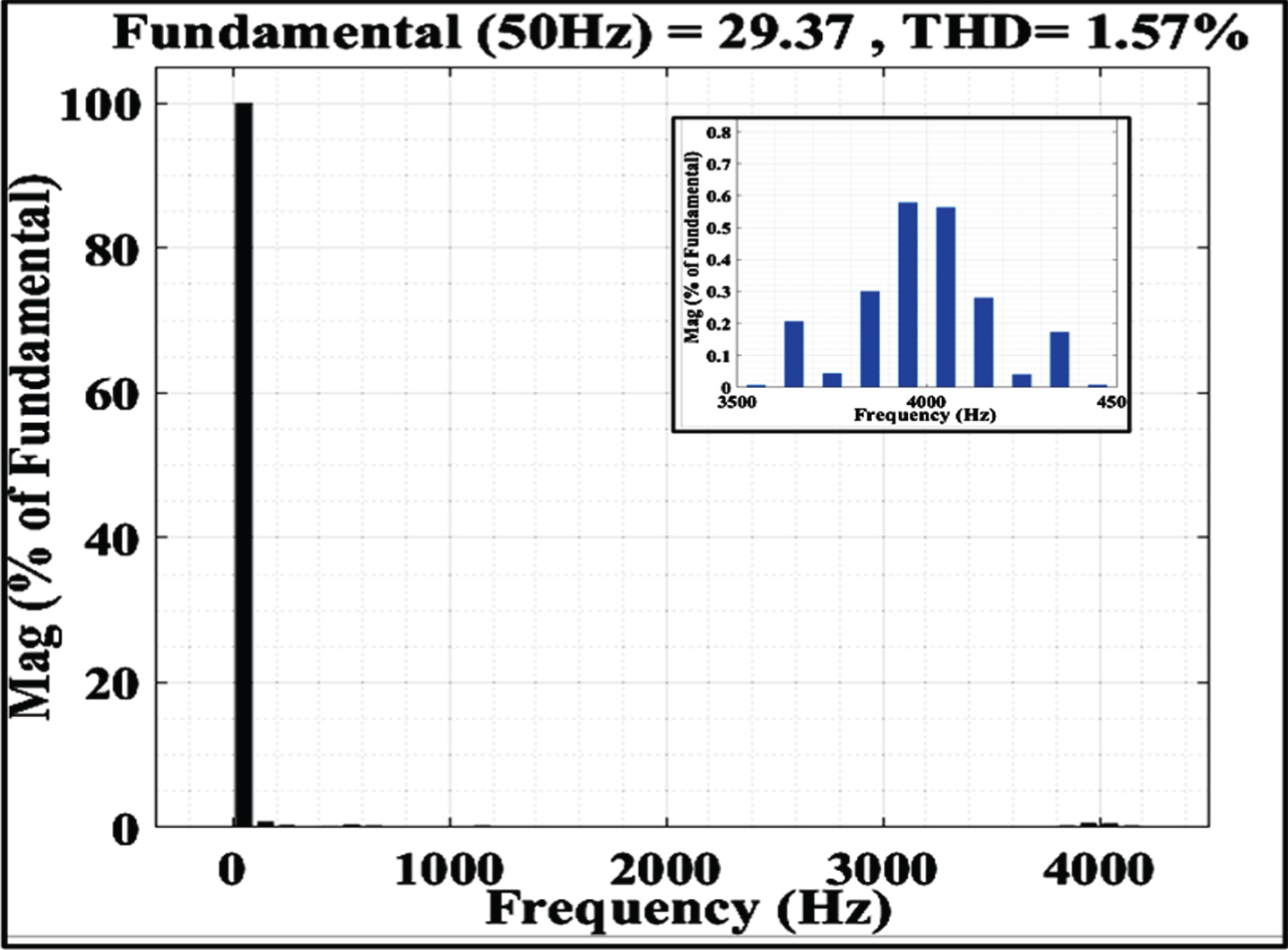
Harmonic spectrum profiles for output voltage and current are shown in Figs. 7 and 8, respectively. As can be observed from Fig. 8, all the triple order and fifth harmonics have zero magnitude (i.e., eliminated), thereby reducing the overall harmonics (THD) in voltage which is presently coming around 13 % only. The THD in current profile is coming around 1.5 % only. Whereas harmonic spectrum of PDPWM is represented in Fig. 10. Switching frequency considered is 10 kHz for PDPWM. Voltage waveform of PDPWM technique is shown Fig. 9, PDPWM yields a THD of 29.34 % with no harmonics eliminated. Also, the switching losses would be more as it is a high switching frequency technique. Thus, it can be observed that an enhanced harmonic profile is obtained for both the voltage and current spectrum for proposed GA based optimum angle technique.
Harmonic Spectrum of Current Waveform with GA Applied.
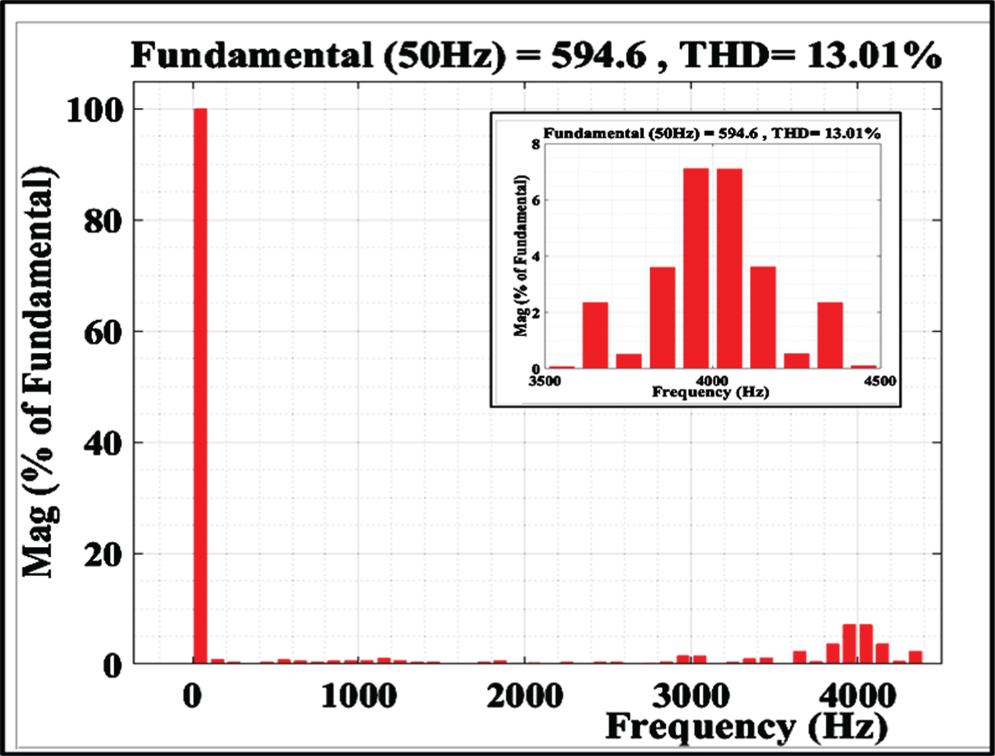
Harmonic Spectrum of Voltage Waveform with GA Applied.
Voltage waveform obtained from PDPWM.
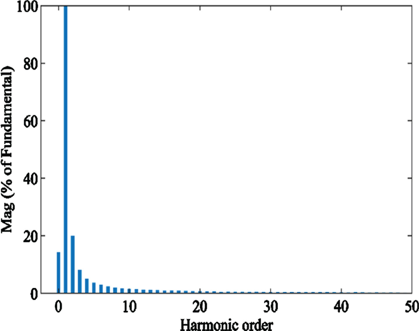
FFT of voltage waveform obtained from PDPWM without GA.
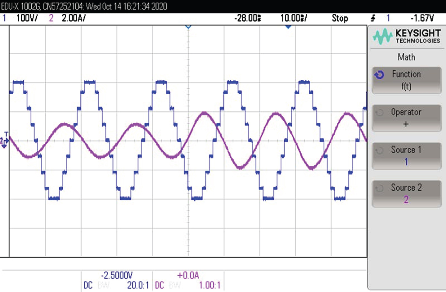
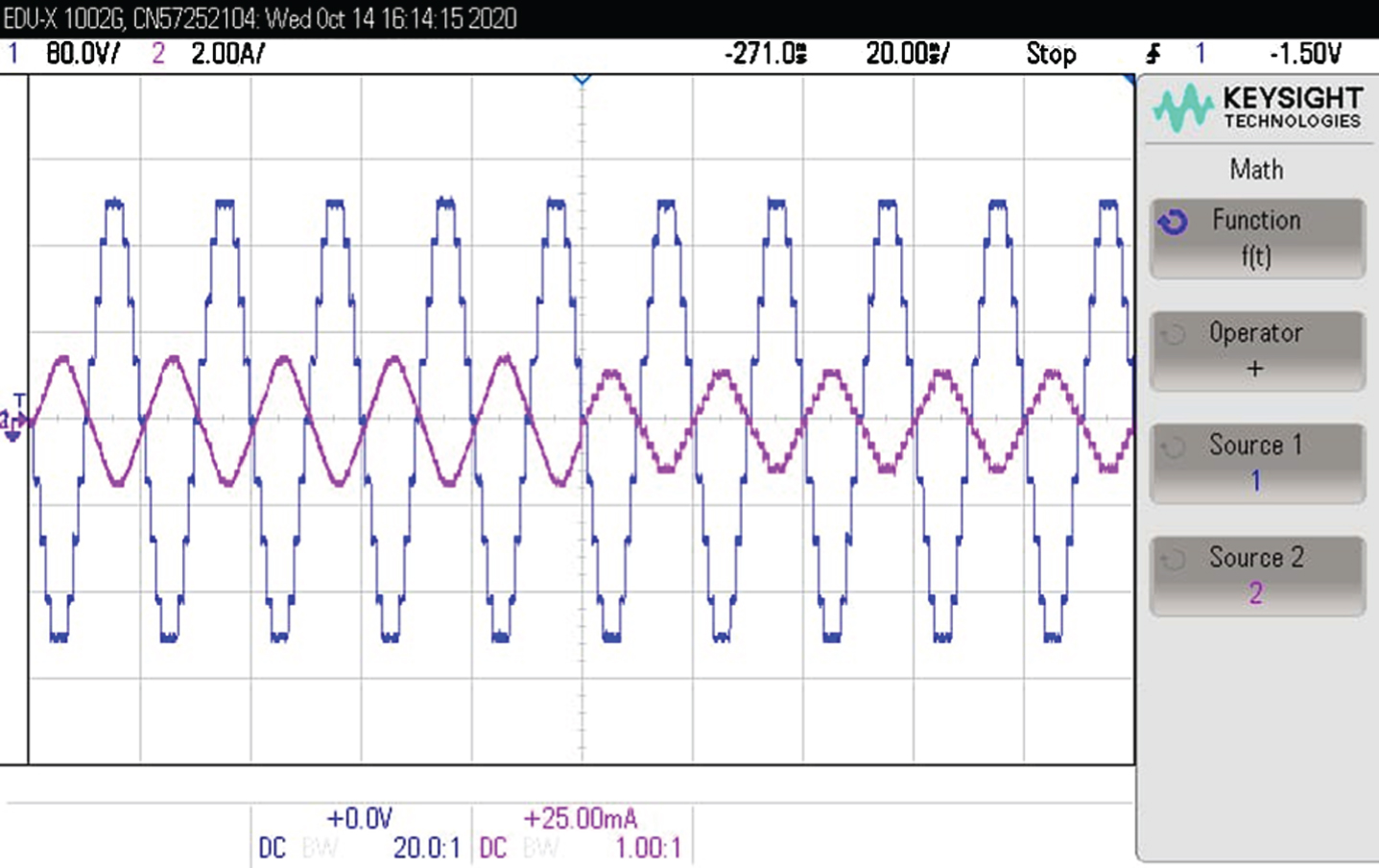
To validate the findings of simulation, the technique is validated using Typhoon HIL 402 setup. Results obtained from HIL setup are represented in from Figs. 11 to 14. Figure 11 represent the voltage and current waveform showcasing different dynamic condition. As observed from Fig. 11, the current is increased after one cycle and which decreases again after five cycle. The same sequence is repeated in order to test the dynamic performance of the control technique. It is observed that the voltage remains at the same level, hence the output voltage does not gets affected by the change in the output current (load). Figure 12 shows the zoomed voltage and current waveform with increase in current. Figure 13 shows the zoomed voltage and current waveform with decrease in current. Voltage and current waveform with 180 degree phase-shift obtained by Typhoon HIL is shown in Fig. 14. The voltage and current waveform obtained from HIL, is in accordance with the simulation results.

Voltage and current waveform showcasing different dynamic condition obtained by Typhoon HIL.
Voltage and current waveform (in zoomed) with increase in current obtained by Typhoon HIL.

Voltage and current waveform (in zoomed) with decrease in current obtained by Typhoon HIL.
Voltage and current waveform (at 180 degree phase-shift) obtained by Typhoon HIL.
In this paper, PEC inverter is adopted for hybrid energy source for economic and reliable operation. The low switching frequency operation is proposed using genetic algorithm to minimize the losses and harmonics in the voltage and current waveforms. A comparison with high frequency modulation technique phase disposition pulse width modulation (PDPWM) technique is done. It is concluded that power quality of the inverter is improved by using SHE based on GA. All the triple order and fifth harmonics are eliminated, with overall reduction in harmonics (THD) in the output voltage and current. Experimental validation of the proposed scheme is done Typhoon HIL 402 setup and it is observed that the experimental validation is in line with the simulation analysis. The output results depicted show better performance.
Footnotes
Acknowledgments
The authors would like to acknowledge the financial support by the World Bank and Ministry of Education, Government of India under Minor Research Grant Scheme No. BGSBU/TEQIP-III/RGS/012 of TEQIP-III Project at BGSB University, Rajouri, India.
The authors also acknowledge the financial support from collaborative research grant scheme (CRGS) project, Hardware-In-the-Loop (HIL) Lab, Department of Electrical Engineering, Aligarh Muslim University, India, with project numbers CRGS/MOHD TARIQ/01 and CRGS/MOHD TARIQ/02.
The authors also acknowledge the technical support provided by the Hardware-In-the-Loop (HIL) Lab, Department of Electrical Engineering, Aligarh Muslim University, Aligarh, India.