
Abstract
This paper presents the design and development of Modular Multilevel Inverter (MMI) to reduce Total harmonic distortion (THD) using intelligent techniques towards marine applications. Many researchers have described the additional advantage of inverter control challenges such as voltage imbalance, increasing the number of voltage levels, power quality issues, reducing the number of semiconductors switches and achieving higher efficiency. Under the intelligent techniques, the implementation is carried out with aid of Artificial Neural Networks (ANN), Fuzzy Logic Controller (FLC) and Adaptive Neuro-Fuzzy Inference System (ANFIS) to calculate the modulation index (ma) and switching angles (θ) for MMI. Based on the calculation, it is trained to form a mapping between inputs and outputs for obtaining reduced Total Harmonics Distortion (THD). The objective of the intelligent controller is to control the inverter for regulating the output voltage with lowest THD. The proposed control structure has been estimated and compared for better robustness in terms of switching angle and modulation index with least THD in the inverter. Simulations and prototype models are made to analyze the controller’s performance, for inverter output voltage and harmonics. This proposed system is designed for marine lighting load application. The FPGA performance with all intelligent methods are analyzed by in SPARTAN3E500 FPGA device.
Keywords
Introduction
The modern renewable energy sources (RES) have been converted and control power to situate on the several applications. Power electronics converters play an important role in all stages of electric power processing, such as generation, conversion, transmission, distribution, and conditioning. Natural fuel energy, such as coal or gas, is not a reliable resource for meeting all of the needs of today’s human beings [1]. The use of fossil fuels has resulted in significant environmental damage and energy depletion. This problem is a blatant imitation of an alternative energy source. This is why there has been so much effort spent exploring alternative energy resource alternatives [2]. RES have been employed as a supplement to fossil fuels since they generate green energy and are abundant. As opposed to conventional generators, RE sources capture energy from uncontrollable natural resources, whereas conventional generators create fossil fuels, which are totally within the control of the system operator. In addition, advanced power electronic converters can be used to control the output of RES to some extent [3]. The practical issues with the renewable energy transformation scheme can be split into two categories. The first category of issues concerns power converter interconnection issues with stand-alone and grid-connected systems. In Distribution Generation (DG) systems, the second group has issues with power flow and control [4].
As a result, the amplitude of the DC voltage generated (for example, from photovoltaic (PV) arrays and batteries) is less than the grid voltage (in grid-connected scenarios) or the required load voltage (in stand-alone cases). While the power capacity of RES is naturally limited by factors such as lack of sunlight, manufacturing tolerances, thermal gradients, and dirty or obstructed panels [5]. The development of several new multilevel inverters recently introduced in industry, particularly medium-voltage converters, has focused on the interface with RES for cost reduction, increased reliability, efficiency, power capability, and lower enlargement times, as well as more challenging application requirements [6, 7]. In this sense, the large amount of research around the study of existing multilevel topologies is taking place around the development of new topologies and control algorithms as well as the dynamic interface between the converters [8].
The quality of power has a direct economic effect on several industrial consumers. Nowadays most industries have more automation and modern equipment that is often much more sensitive and critical equipment major issues are power quality problems. The term “power quality” is used to describe two features of the power supply: voltage quality and supply reliability [9, 10]. Improved voltage quality is offered by active power filters. Shunt and series active filters are performed one or more of the functions required to compensate power systems and to improve power quality [11]. Power electronic circuits can now be used for energy distribution and control due to improved dependability and device innovations with higher power ranges and blocking voltages. The MMI has involved attention for the solar PV integration with nonlinear loads. The MMI can also be extended to the stand-alone PV system. In standalone photovoltaic inverters, the alternating current necessitates operating at 230 V, 50 Hz for residual applications. In case solar array voltage is low, there is the need for additional boost converter (DC-DC) voltage is typically connected to an inverter. Improving the output waveform of the inverter decreases its respective harmonic content, decreases the level of Electromagnetic Interference (EMI) and is suitable for renewable photovoltaic energy which is of great concern is efficiency and power quality. The primary objective of PV systems is to produce active power. By using multi-functional inverter on PV system, active filter functionality, voltage and reactive energy maintenance can be accomplished. The emphasis is on the growth of several new inverter topologies mainly the medium voltage converters that have been recently introduced in the industries. This problem can be eliminated by using power quality improvement techniques. Hence, the research work focuses on the development of power quality improvement intelligent techniques such as ANN, FLC and ANFIS to overcome the above problems.
Multilevel Inverter (MLI) are essential to energy conversion processes for renewable energy applications in solar energy systems. Power electronic converters have a great role in the entire transforming steps through the conversions of electric power. This implies that the dynamics with in the converters must be taken into account with their corresponding constraints, which should be considered by the control strategies as a part of the overall control objective. All these motivate the research field the study of various multilevel topologies, the development of new circuit configurations and control algorithms, as well as the complex interaction between converters and external systems in a wide range of applications, like electrical power conversion and conditioning.
Intelligent techniques provide the switching angle (θ) for single phase solar PV fed MLI. The research investigates the effectiveness of intelligent techniques such as ANN, FLC and ANFIS. Based on the training system, the rules form a mapping among inputs voltage (Vin), current (Iin) and outputs modulation index (ma), switching angles (θ) of the MLI. When training an ANN with a set of input and output, ANN changes its structure based on external or internal information that flows feed- forward during the learning and training process. FLC and ANFIS controllers are based on rules. The error and change in error are taken as the input; however, the amplitude of voltage and current are considered as the output for the fuzzy logic-based controller referred to by [12–14].
This paper mainly focuses on the design of a reduced switch modular multilevel inverter implemented for solar photovoltaic applications. The developed structure has been derived from the traditional topologies and provide the required output voltage levels with only few passive elements. As per the MLI-HDBK-2017F standard the ability of an inverter to work under any predetermined condition is considered as its reliability and this reliability can be improved by reducing the total number of switches in the inverter. It has been identified that the output voltage of the inverter contains higher order harmonics and these harmonics have to be nullified to improve the quality of power at its output. To improve the power quality at the output of inverter and for proper voltage regulation the proposed system is tested with three intelligent controllers.
A detailed investigation for the proposed work is carried out in this paper. Section 2 explains the problem formulation of proposed MLI. Section 3 describes the system configuration, operation strategy MLI and outlines the control scheme of modular multilevel inverters using intelligent techniques. Section 4 describes the performance of simulation results. Section 5 discusses the experimental results.
Problem formulation for proposed MLI
The 11-level inverter proposed system derives this equation. While m i is the total number of switching angles for the proposed inverter in Equations (1 to 7).
The modulation index is defined as fundamental voltage divided by total number of DC component voltages in equation (8), where is the Fourier coefficient and is the nominal DC voltage.
The optimized switching angle of 11- level of the proposed inverter is given in Equations (9 to 14).
The nonlinear equation systems are utilized to calculate the optimal switching angle, which involves the above equation. This limitation is resolved in the proposed method by implementing the several intelligent methods such as FLC, ANN and ANFIS.
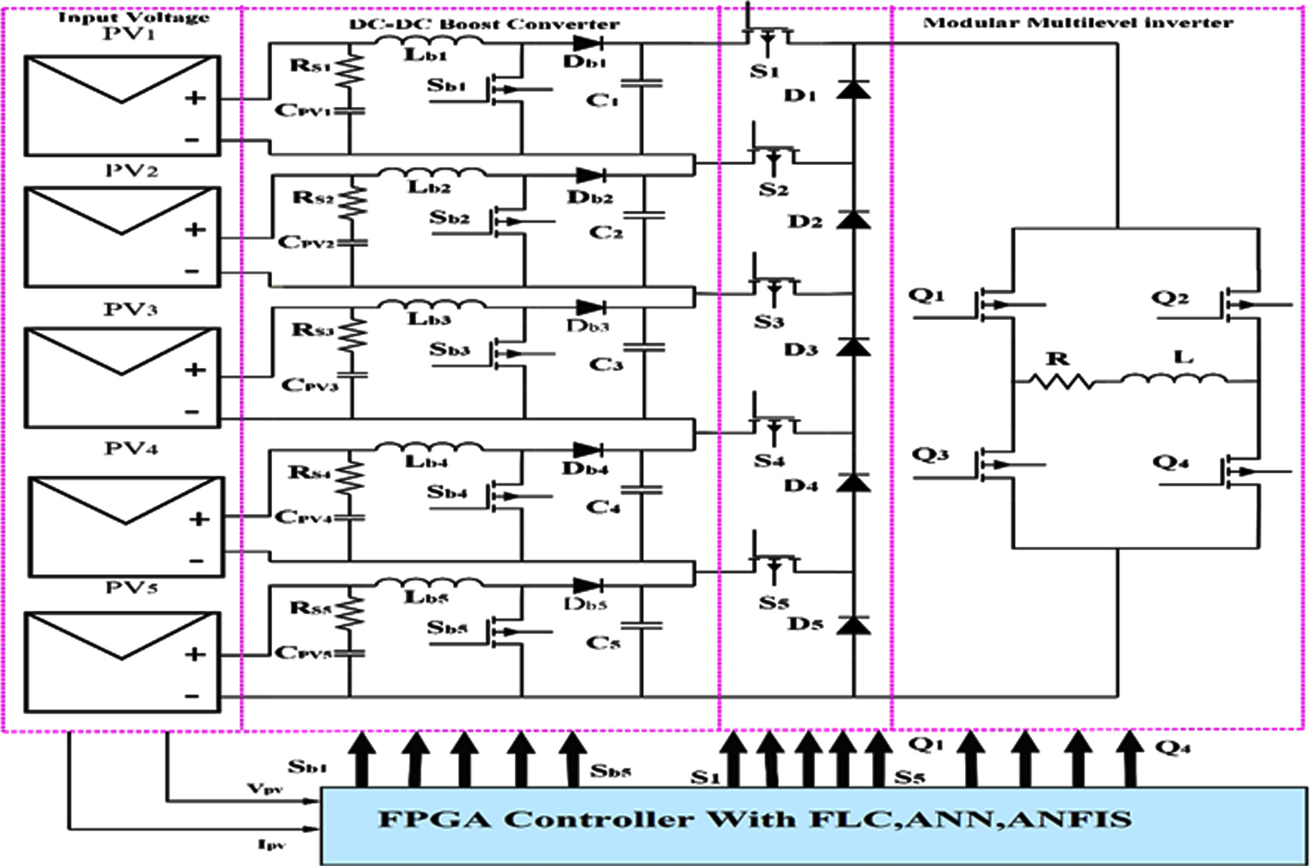
The proposed system involves the design of a solar PV fed modular multilevel inverter in Fig. 1. In general, multiple photovoltaic panels are connected to the multiple boost converters for gaining the required MLI output. In the proposed work, ten solar PV panels are connected to the combinations of 30 W panel series modeled to power the five-stage inverter of eleven level output voltage obtained [15], presented a firefly technique for training an ANN to restore power from a voltage source converter during a blackout. The ANN-FLM method was used to overcome the disadvantage of the soft start-up. The results of a comparison analysis between the ANN-FLM and conventional PI controllers show that the ANN-FLM controller is dynamic [16], proposed a hybrid (ANFIS–PSO) hybrid (maximum power point tracking) MPPT method based on adaptive neuro-fuzzy inference for gaining fast and full PV capacity with zero oscillating monitoring. The technique used provides incredible power to increase PV extraction.
Control scheme of modular multilevel inverter using intelligent techniques.
The input voltage separator in Fig. 2 is made up of five solar PV modules labeled SPV1, SPV2, SPV3, SPV4, and SPV5. The separated voltage is sent to the circuit, which is made up of controlled and uncontrolled devices labeled S1, S2, S3, S4, S5, D1, D2, D3, D4, and D5 is integrated into one H-bridge (Q1, Q2, Q3, and Q4) with load.
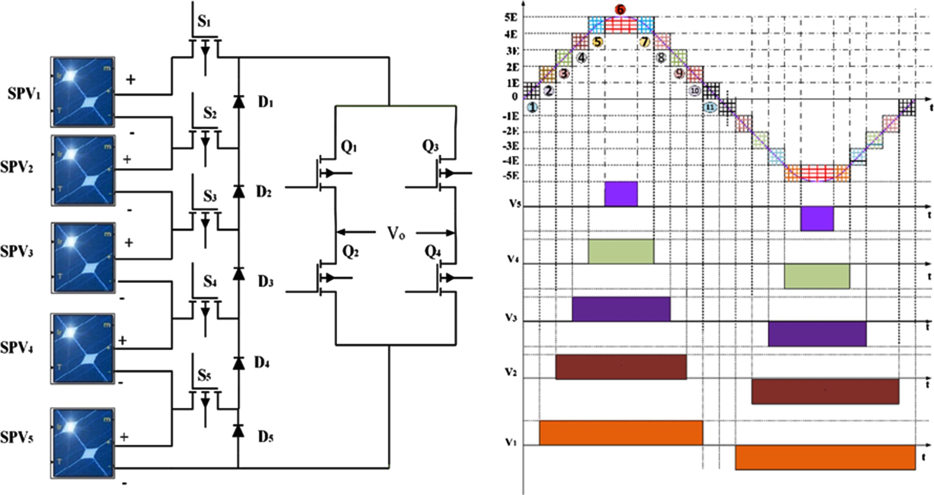
Proposed multilevel inverter.
For PV applications, the suggested MMI architecture is a viable option. In general, obtaining the needed MMI output necessitates the use of several PV panels in conjunction with various boost converters in Equations (15 to 17)
Total number of switches,
Number of levels
Number of levels
Where U is the total number of switches and S is the number of switches without the H-bridge. Both symmetric and asymmetric topologies are satisfied by the 11-level inverter. With the structure of MLI modified, the suggested topology operates under both symmetric and asymmetric situations. In the next sections, we’ll look at both possibilities in depth.
The solar PV’s more benefits and economic aspect is required to develop the novel power electronic inverter topologies using intelligent techniques such as FLC, ANN and ANFIS to simulate in MATLAB. The performance analysis has been carried out to find the THD closed loop system shown in Fig. 3.
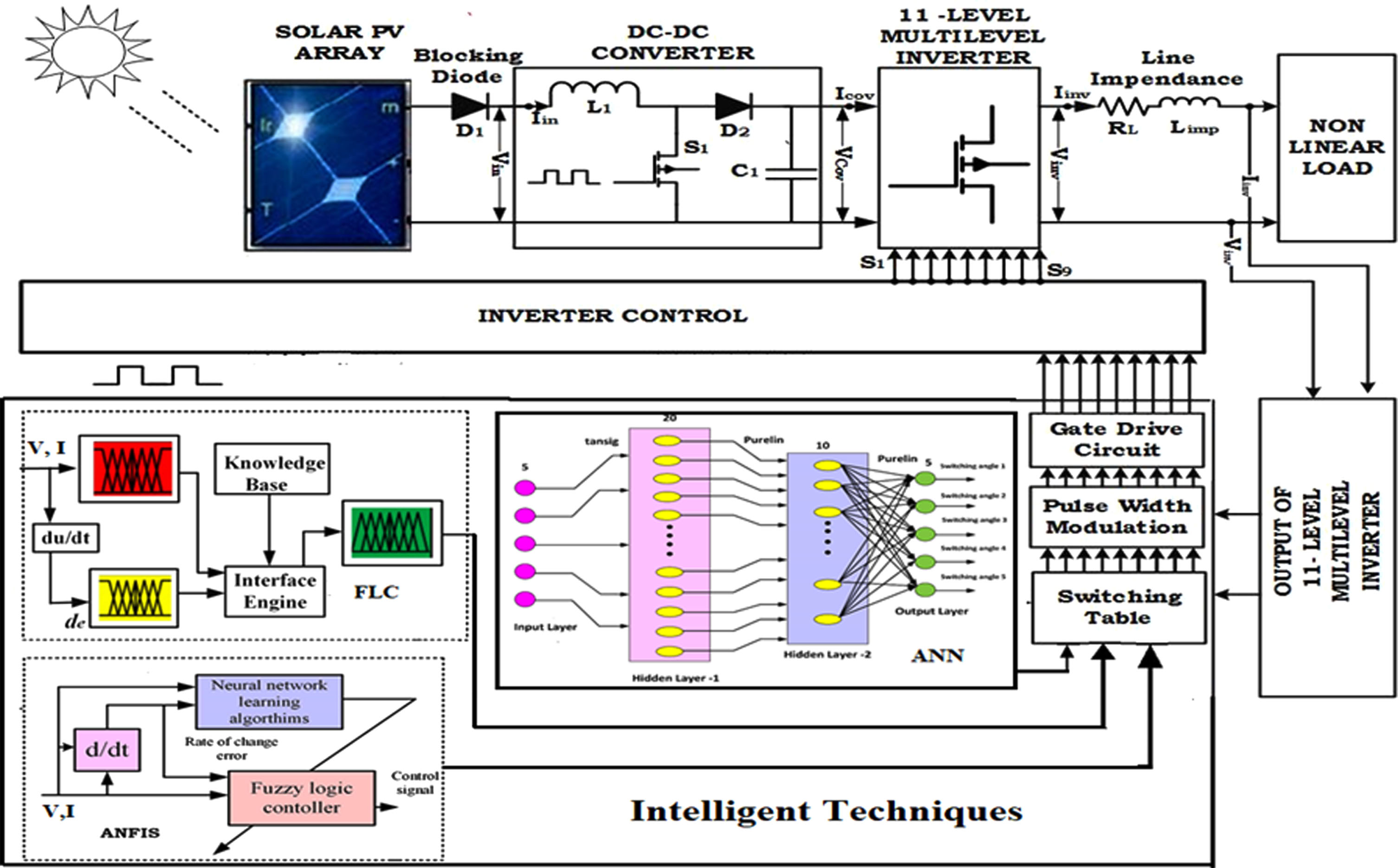
Control scheme of the proposed inverter using Intelligent Controller.
Intelligent techniques such as Fuzzy, ANFIS and ANN are implemented with MMI for solar PV application. The single phase 11- level inverter is simulated and trained to get the best value of the modulation index and switching angle with the least value of THD. The analysis of the different values of modulation index is performed with the output voltage and current for the lamp load. The proposed FLC has established two important main tasks: (1) estimates the inverter switching angle and calculates the THD and (2) reduces error speed in fast response using the rules-based system with lower harmonics. FLC is utilized mainly to follow the four necessary steps: (1) Analog fuzzifier input is converted into fuzzy variables, (2) Storing fuzzy rules and describing the fuzzy performances, (3) Making inference and associating fuzzy input varies with the rules and (4) Converting defuzzifier into the fuzzy output for getting the actual target. In FLC, a multi objective optimization model which is being used to determine the best combination of switching angles with lowest THD.
The ANN’s basic structure is made up of three layers: inner, hidden, and exterior. The input layer’s numeric data is saved and processed by the hidden layer. The size and number of hidden layers are determined by the task provided to the ANN. The optimal mapping is designed depending on the performance error and training period by adjusting the number of neurons in the hidden layer.
The real- time varying solar radiation to calculate the optimum switching angle solution stored in a lookup table. The ANFIS controller maps the data set for giving multi (or) single input to achieve single output. The ANFIS has a general structure layer such as input layer, fuzzification layer, product layer normalization layer and defuzzification layer. The ANFIS constructs fuzzy inference rules depending on the input of modulation index, error speed and output of switching angle with THD. The fuzzy inference mechanism tunes as error speed and the switching angle by the NN learning mechanism with least THD.
The simulation result shows the testing of three different controllers in a single phase with eleven level MMI with load. The simulation result was carried out in MATLAB/Simulink.
Simulation result and implementation procedure of fuzzy systems
The proposed switching strategy is based on FLC, which is commonly used to regulate complicated nonlinear systems with an extreme mathematical model while also reducing errors. The FLC is used in the proposed switching method. The controller in FLC operates in specified member functions (MFs), both input and output, with specified rules, making it more dependable and efficient. Models termed Mamdani and Takagi-Sugeno FLC are two different types of FLC [17, 18]. The eleven level MMI is determined with five switching angles using FLC lookup Table 1. The eleven level MMI contains five switches for level generation and four switches for polarity generation, and the FLC controller lookup table is designed using the based switching pattern.
Extracting information and converting it into production rules
Extracting information and converting it into production rules
Figure 4 shows the proposed inverter that is used to design the FLC. The nine switches of the FLC controller with 6 input (INs) and 6 output (OPs) are required to generate the pulse pattern of the switch over a cycle. The mamdanian FLC appears normally triangular and trapezoidal membership function is constructed to calculate the switching angle for marine application. The eleven level MMI determines with five switching angle using FLC lookup table. The eleven level MMI has formed five switches for level generation part and other four switches for polarity generation part which the based switching pattern is utilized to design the FLC controller lookup table.
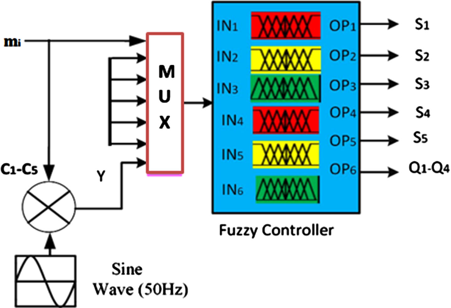
PWM of inverter using FLC.
There are nine semiconductor switches in the 11-level MMI in the form of (S1–S5) switches, which are parallel connected to sources. The remaining four are linked to H bridge switches (Q1–Q4). For S1–S5 inverter control pulses and Q1–Q4 level control pulses, the bipolar triangular and sinusoidal waves are compared to produced PWM based on fuzzy rules. The FLC structure is completely developed utilizing the inverter’s switching pattern and a pulse generator. The fuzzification membership input is intended as a switching magnitude in the range of (IN1–IN6) (–1, 0, 1). The first quarter cycle is represented by (0°–90°) while the second quarter cycle is represented by (90°–180°). Similarly, the negative range from –1 to 0 represents the third quarter cycle (180°–270°), whereas the fourth quarter cycle (270°–360°) is represented by the positive range from –1 to 0. Finally, six OP membership functions based on fuzzy to rules are built in defuzzification to produce the required result cited by [19, 20].
Fuzzy logic is employed to generate data sets in terms of harmonic voltages and inverter switching angles in the proposed system. The output of the NB value is 0.1 while the output of the PB value is 1. The output of the PS value is 0.66. The output of the ZE value is 0.5. The linguistic values in the input range from or declaration are NB = –1600, –10, –4, NS = –8.06, –3.96, 0.02646, ZE = –3.2, 0, 3.2, PS = 0, 4, 8, PB = 3.52, 9.92, 1550.Using the switching angles of inverters used in MLI, the Fuzzy Inference System (FIS) is used to provide harmonic voltages of various orders.
A learning set is a collection of pairs of input patterns and desired output patterns. Each pair represents the network’s expected response to a specific input. A supervised learning is a subset of a larger data set that is used to fit (train) a model for predicting or classifying values that are known in the training set but unknown in other (future) data. The training dataset is used in conjunction with the validation and/or test sets to evaluate various models.
The simulation result of FLC consists of switching angles. MLI switching angles are generated by the FIS inputs. Harmonics are computed by rules after fuzzification and depending on the specified fuzzy values of switching angles. Finally, the harmonics results are obtained by using different values of optimum switching angle which is considered as a data set. As a result, the data set generated by FIS is made up of switching angles and MLI harmonic distortion. Using the data set, optimal switching angles for when the controlling modulation index varies without any output voltage. The value of THD is changing consequently. The proposed inverter determines the optimum switching angle for producing the eleven-level output voltage by using FLC. Figure 5(a) and (b) shows the output voltage inverter with THD.
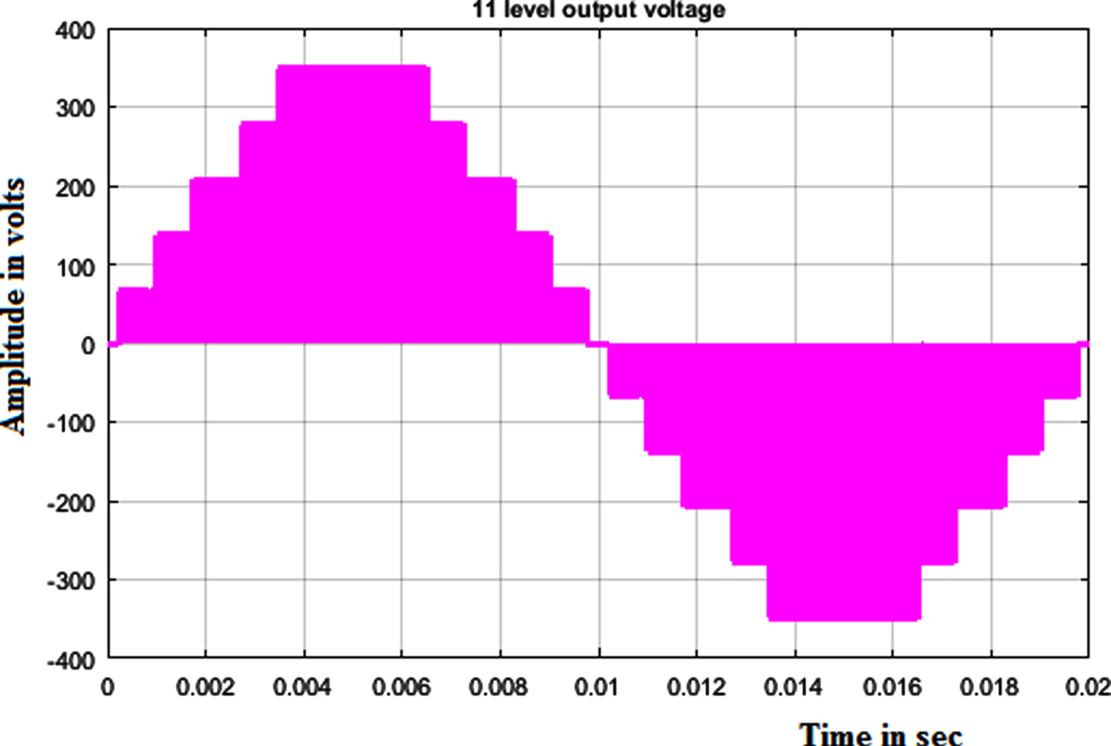
Output voltage of FLC.
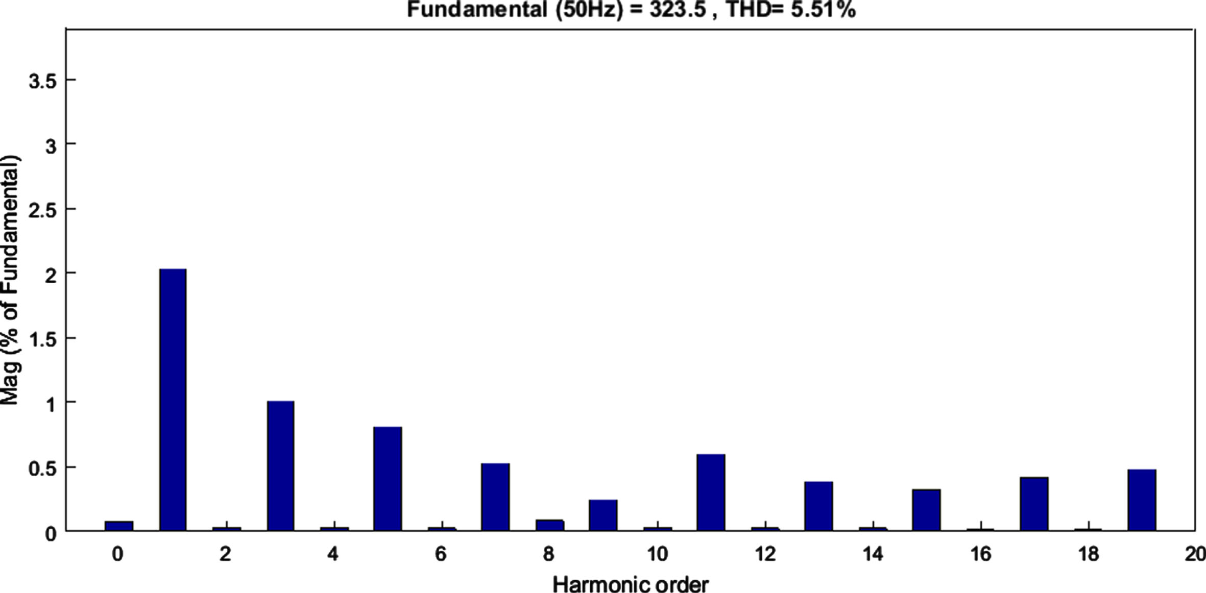
Harmonic spectrum using FLC.
ANN is applied in an eleven-level inverter to investigate the effectiveness of the same for calculating the switching angles of MLI shown in Fig. 6. The Neutral Network (NN) is trained to form a mapping between the inputs (solar input voltage) and outputs (switching angles) of a MLI with least THD. By triggering the circuit, the switching angle produced by the NN is converted to equal gating pulses, which are also delivered to the gate terminal of the IGBT switches in the MMI. The triggering circuit uses a triangular waveform that is linked to a modulating signal whose variations are directed by angle sets retrieved from the NN. The generated pulse is fed to the gates of the MMI switches. The harmonic component’s amplitude is determined by the conduction angles [21]. There are eleven levels in one cycle of the output voltage waveform including zero in Fig. 6. The two-layer feed forward error back propagation network is better suited to power electronics applications and can be used until the desired result is achieved [22]. Table 2 shown are the simulation parameters of ANN and detailed analysis of ANN controllers determines the optimum switching angle, which is obtained in both normal and abnormal conditions for the entire system [23, 24].
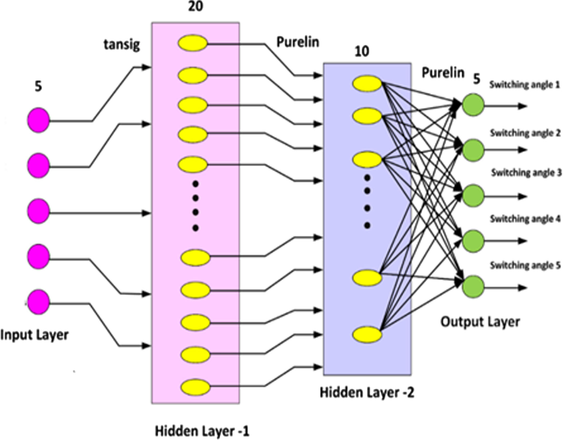
Architecture of ANN.
One hidden layer of 20 neurons and a second hidden layer of 10 neurons comprise the feed forward multilayer perceptron. The Levenberg-Marquardt backpropagation (LMBP) algorithm is trained ANNs that are linked by weight functions. The steepest descent (error back propagation) and Gauss Newton algorithms are arranged in LM algorithms, and the training process switches between these two methods. When compared to other algorithms, they are fast back propagation algorithms for feeding forward neural networks with steady convergence and do not require extra memory. The ANN process decreases the error signal to obtain the targets. The mapping is accomplished by modifying weights, which are internal parameters. This is referred to as the learning or training process. The analysis of various switching angles and modulation index with least THD is trained in practical implementation as shown in Fig. 7(a) and (b).
Output voltage of ANN.
Harmonic spectrum using ANN.
The tangent-sigmoid function is activated by feed forward ANN for function of hidden layer and linear. The switching angle is generated by the neural network to convert the corresponding to gating pulse by triggering circuit. The training and testing sets were 70% and 30%, respectively. Normally, 70% of the available data is set aside for training. The remaining 30% of data is partitioned equally and referred to as validation and test data sets.
ANFIS is applied to the proposed 11-level to estimate switching angle for optimum harmonic which is trained on the database and performance system. As shown in Fig. 8, the ANFIS is a multilayer network that allows neural networks to be used in conjunction with fuzzy logic. In order to solve nonlinear and difficult problems, the neuro-fuzzy controller combines neural networks and fuzzy logic. The objective of this ANFIS technique is to create a new structure for estimating the switching angle in order to obtain the THD optimally.
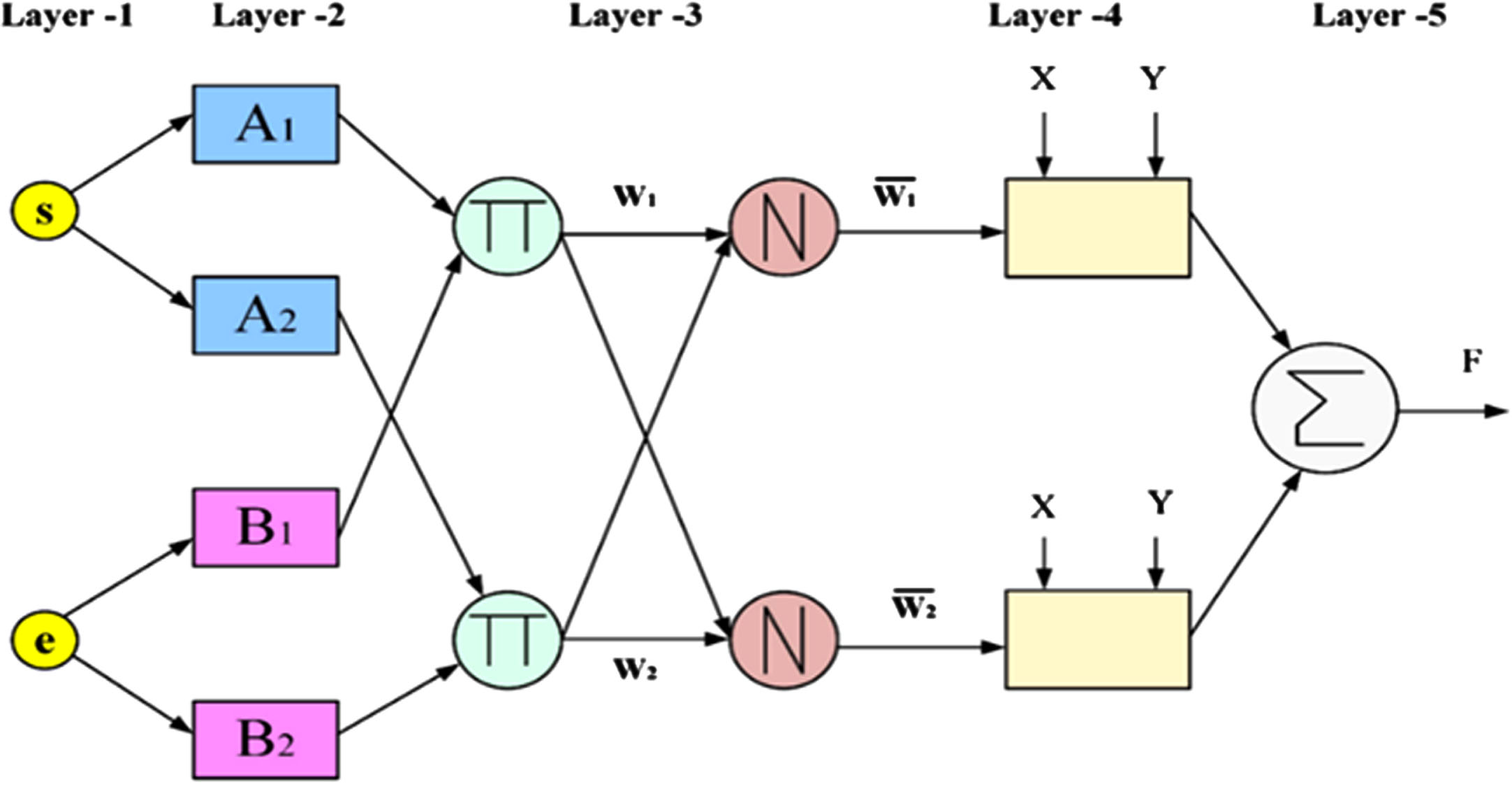
ANFIS of architecture.
Simulation parameters of ANN
ANFIS is a basic data learning method that uses fuzzy logic rules and processes to convert provided inputs into desired outputs using a network of NN processing elements and informative connections that are weighted to map numerical inputs into outputs. The ANFIS is mainly recommended for (1) the simple procedure and fast learning system, (2) accurate and strong generalization skills, (3) easy to understand fuzzy rules and (4) easy to observe numeric knowledge for problem solving. The typical architecture of an ANFIS presents a multilayer feedforward network in particular with two input signals (x,y) and output signals (f) with five layers. The first layer includes the nodes of (Ai, Bi) comprising the membership allocated to each input (x, y) with the proposed input angle (s) and error (e) speed. The membership function tunes the training data. The second layer identifies the rules. The third rule calculates the uniform firing strength of each rule. Fourth layer is given input signals to calculate the model layer and the fifth layer calculates the overall output by all incoming signals. The performance of brushless DC motors by using ANFIS controllers. The ANFIS controller has been compared to other controller and performance analysis of speed and other control parameters. ANFIS controller using MPPT approaches for solar PV systems. The ANFIS is implemented in an FPGA board by a trained database system [25].
The training data has to be carried out with a limited number of input and output data with the help of ANFIS model. The formation of FIS is based on the fuzzy rules extracted from input and output data. The next process is using NN to fine tune the rules with training to develop the fuzzy model structure and ANFIS techniques the network is trained on. After training the data the final result can be validated and predicted. In the proposed ANFIS model, each input variable of switching angle and modulation index is trained in the fuzzy rules and evaluates the output data. The next process of the neural network system is fine tuning the optimum output variables of eleven level output voltage with least THD and for minimizing the error speed as shown in Fig. 9(a) and (b). The simulation result shows the verification and training of 296 input and output data pairs to obtain the optimized THD. The obtained optimally selected data are trained.
Output voltage of ANFIS.

Harmonic spectrum using ANFIS.
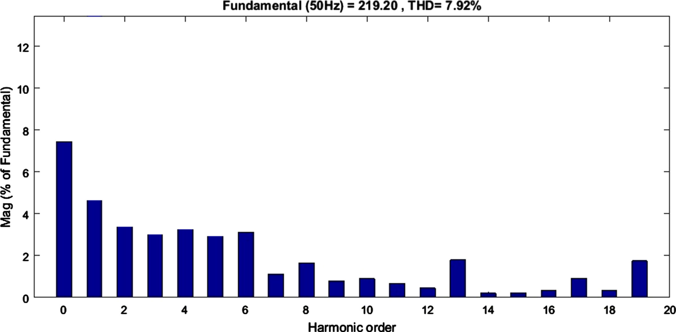
The harmonics spectrum waveform obtained by using ANFIS controller in the proposed inverter. The proposed simulated work is for measuring the speed of the motor and harmonics of the inverter by using the intelligent controller and also for analyzing the performance. The ANFIS model provides the simulation result of switching angle with least THD, which has been indicated in Table 3.
Comparison of simulation results
The proposed system consists of PV panels, boost converter, modular multilevel inverter with RL Load. The output of inverter current, voltage, speed of induction and THD sensed are finally connected to the FPGA controller. The output is delivered as two external ADC converter which is sensed the values into suitable digital signal for FPGA. The FPGA hardware generates the output PWM based on switching angle. This proposed system is designed for marine lighting load and water pumping application. The FPGA performance with all intelligent controller methods is analyzed by SPARTAN 3E 500 FPGA device. The proposed controllers such as FLC, ANN and ANFIS are programmed in model sim software interfacing with FPGA board. It allows users to design hardware circuits quickly. Increased FPGA configurable logic capacity and lower FPGA costs have made it easier for developers to integrate FPGAs into their designs. The SPARTAN 3E 500 FPGA, a 90 nm low-cost FPGA device, is used for real-time exploitation. Figure 10 shows the detailed analysis of the complete experimental model for the proposed inverter connected with Lamp load.
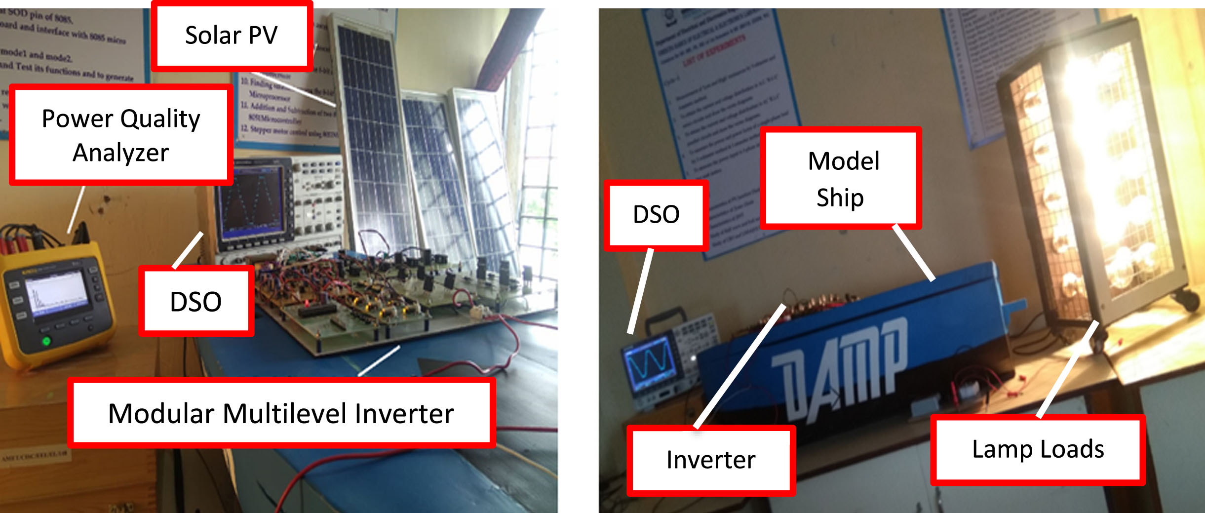
Proposed inverter with emergency lighting loads.
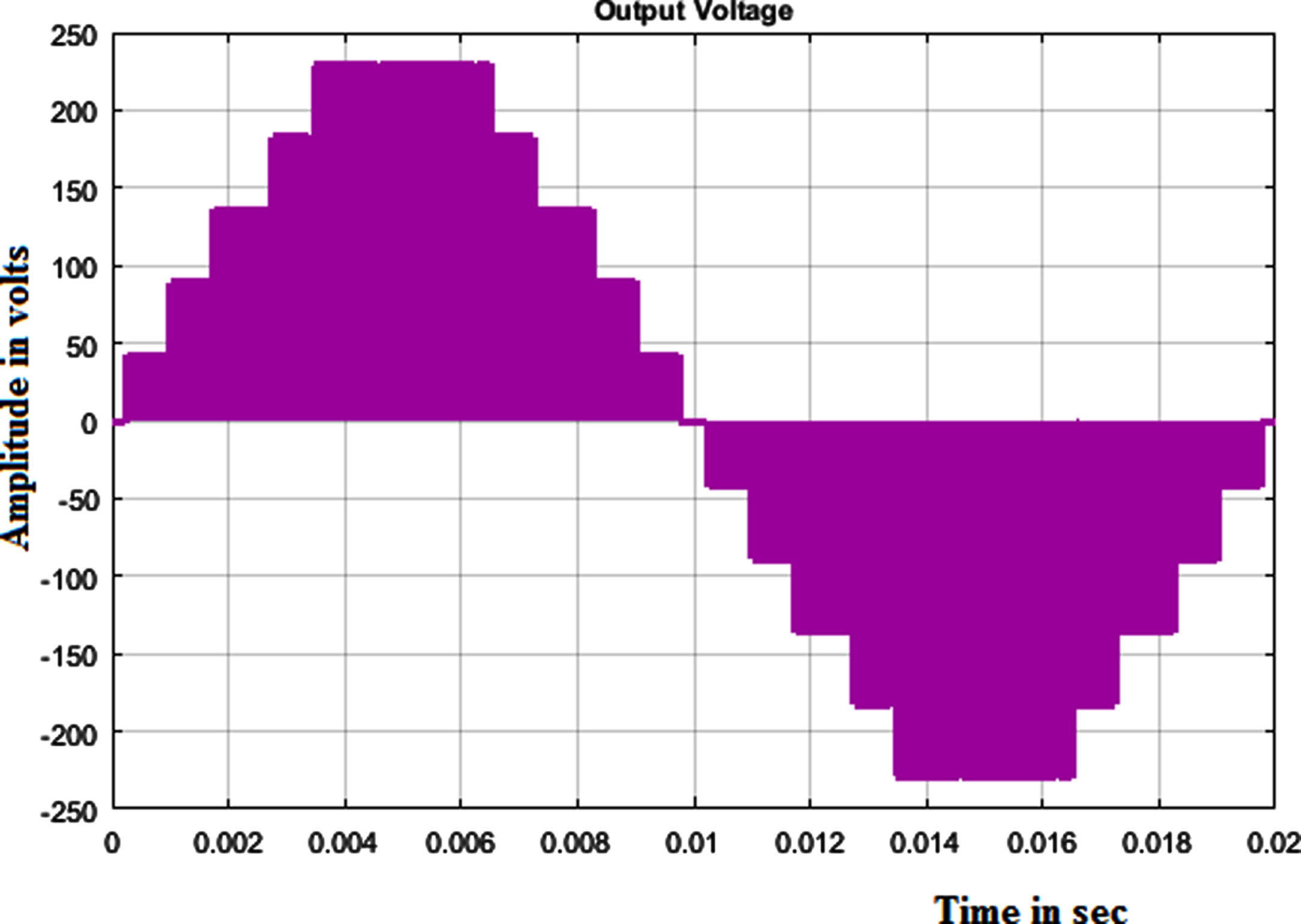
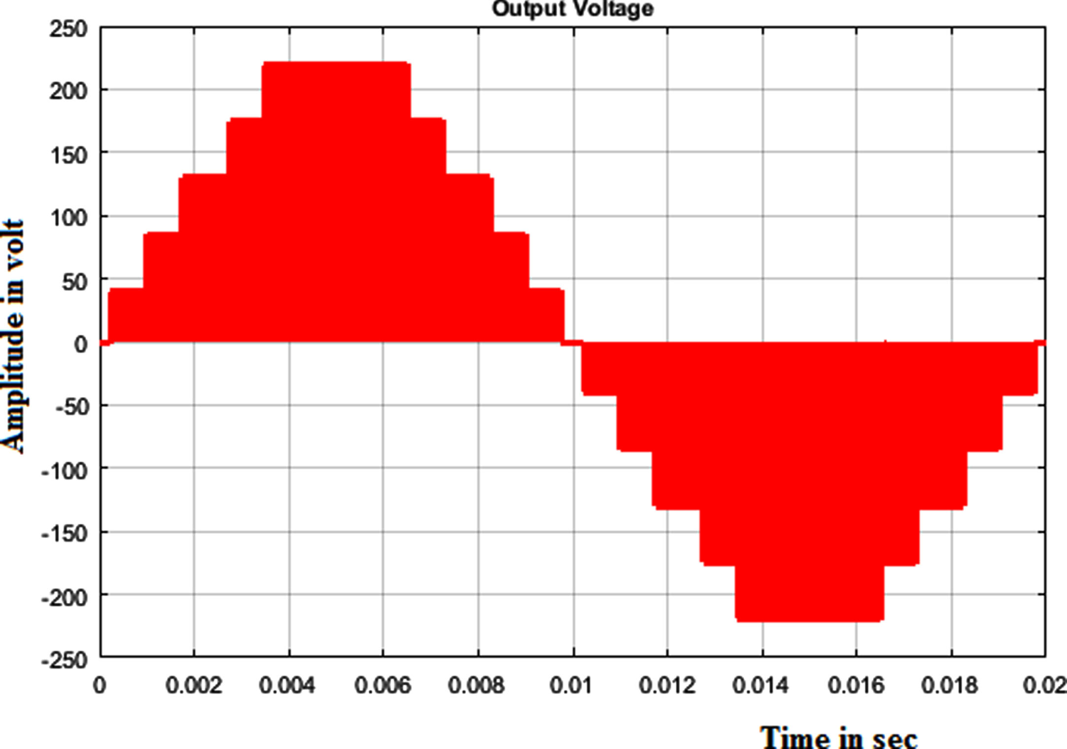
The hardware design of description and functionality tool of model sim 6.3f is used. The running frequency of the FPGA board at 17.50 Hz clock divider with 2.4 kHz to generate PWM signals providing for S1 to S5 switches to produce the eleven-level output waveform Q1–Q4 and Q2 - Q3 are generated by the polarity waveform. Figure 11 shows the output voltage of the eleven level inverter.

Output voltage of eleven level inverter.
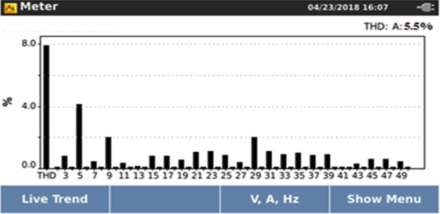
Figure 12 shows the experimental harmonics spectrum of ANFIS with lamp load. Figures 13 and 14 shows the Experimental harmonics spectrum of ANN and FLC with lamp Load.

Experimental harmonics spectrum of ANFIS with lamp load.

Experimental harmonics spectrum of ANN with lamp Load.
Experimental harmonics spectrum of FLC with lamp Load.
In Xilinx project navigation devices, the VHDL coding generated device of SPARTAN 3E 500 FPGA at 50 MHz plays a vital part in coding. The FPGA has primarily concentrated on three key parameters: (1) reducing the size of the controller’s programmed area, (2) improving the controller’s dynamic performance, and (3) lowering power dissipation. Various sophisticated methodologies using THD are used to evaluate the proposed inverter in the emergency lights and RL loads. To design and finally generate a bit file for the target device, the Xilinx project navigator tool was utilized. The three measured values for measuring FPGA performance characteristics are speed, area, and power dissipation. In this MLI architecture, 23 percent of the LUTs are used to achieve a speed of 56 MHz, which is faster than the system clock. The suggested control strategy has the primary effect of lowering the induction motor’s steady-state error and lowering the harmonics of the proposed inverter. The performance of the intelligent controller is tested and also compared with simulation and experimental results as shown in Table 4. The result ensures fast settling time for the ANN controller when it is another controller. Table 5 displays literature review of various intelligent techniques.
Comparison of simulation and hardware results
Comparison of result of intelligent techniques
The research work involves the design and development of a solar fed single phase eleven level inverter with reduced number of switching devices for operating the light loads in marine applications. The power quality improvement techniques for proposed inverter have been carried out with three different intelligent controllers (FLC, ANN and ANFIS). The proposed multilevel inverter topology achieves an enhanced output voltage waveform in simulation and produces 5.51% THD using FLC controller. The other THD values are slightly higher when compared with the FLC controller. An experimental investigation is carried out using 150 W solar PV system with the FPGA controller. The proposed system is tested experimentally using the lighting loads. The triggering pulses to the proposed system is generated using SPATRAN 3A FPGA controller. and obtains least level of harmonics to improve the power quality. The power quality analyzer gives a THD value of 5.5% when the proposed system is operated using FLC controller. The same system produces a higher amount of current harmonics when operated with ANN and ANFIS controllers. Based on the simulation and hardware results, the FLC controller provides the lowest THD when compared with ANN and ANFIS controllers. The advantages of this method include simple computational intelligent techniques without filter. To extend the proposed work presented in this article, a future work may be considered in the following possibilities: The proposed inverter can be extended to the three phase systems. Optimization techniques can be implemented in the inverter such as Particle Swarm Optimization (PSO), Bat Algorithms (BA), Artificial Bee Colony (ABC), Artificial Fish Swarm (AFS) and Firefly Algorithms (FA) to reduces the THD and improve power quality. The control methodology and the proposed inverter can be used for other renewable energy applications.