
Abstract
The primary objective of this work is to optimize the induction motor rotor flux so that maximum efficiency is attained in the facets of parameter and load variations. The conventional approaches based on loss model are sensitive to modelling accuracy and parameter variations. The problem is further aggravated due to nonlinear motor parameters in different speed regions. Therefore, this work introduces an adaptive neuro-fuzzy inference system-based rotor flux estimator for electric vehicle. The proposed estimator is an amalgamation of fuzzy inference system and artificial neural network, in which fuzzy inference system is designed using artificial neural network. The training data for neuro-fuzzy estimator is generated offline by acquiring rotor flux for different values of torque. The conventional fuzzy logic and differential calculation methods are also developed for comparative analysis. The efficacy of developed system is established by analyzing it under varying load conditions. It is revealed from the results that suggested methodology provides an improved efficiency i.e. 94.51% in comparison to 82.68% for constant flux operation.
Keywords
Introduction
Induction machines are widely used in different industrial applications due to their economic manufacturing, robust design, less maintenance and well-established control methods [1]. The generic control techniques require the information of stator or rotor flux vectors, speed and/or position which may be acquired using sensors or estimators. Hardware sensors increase the cost, reduce reliability, require space, wiring etc. Therefore, researchers focus on sensor-less estimation of these parameters [2]. M. Comanescu [3] proposed a model reference adaptive system (MRAS) based rotor flux magnitude and rotor flux angle estimator for control of induction machine. The designed scheme effectively estimates the flux and speed. A. N. Smith et al. [4] used optimal stator flux reference for direct regulation of machine stator flux on the basis of desired torque. The suggested technique provides an effective flux regulation under different speeds and variable load conditions. The effectiveness of designed observer is verified through simulations and experiments. Further model predictive control [5] is also used to regulate field flux in traction Electric Vehicle (EV). The control scheme shows effective performance for voltage disturbances and nonlinear motor parameters.
Practically a significant number of overrated motors operate in under-load conditions, which causes severe economic losses. In general induction machines must be operated at rated flux in order to obtain good transient response, but this leads to significant core losses and efficiency of the system is reduced [6]. Moreover, it is not possible to operate the drive on full load always, which necessitates the minimization of losses for efficient operation [7]. Search control (SC) and Loss model control (LMC) approaches are generally used for loss minimization in electric drives. Search control-based methods are insensitive to change in motor parameters but load perturbations in low load conditions deteriorate the performance. Loss model control approach is fast and does not produce ripple torque, however it is sensitive to inaccurate modelling and changes in motor parameters [8, 9].
Literature reveals the capability of fuzzy logic for handling uncertainty and impreciseness, thus used in loss minimization methods. F. Zidani et al. [10] presented a fuzzy logic-based loss model control strategy to enhance efficiency of asynchronous drive. The designed strategy increases the efficiency from 70% to 83% at 10Nm torque. Further a fuzzy logic-based correction technique is designed to reduce the oscillations around optimum value in LMC [11]. A hybrid of SC and LMC techniques [12] is also suggested along with fuzzy logic-based controller which allows rapid and smooth convergence of flux. The suggested technique provides minimum power losses under light load conditions.
Estimation of torque and efficiency gives important information for diagnosing energy and motor load matching. As motor operates continuously, determination of losses and efficiency is a difficult task. Moreover, installation of a permanent torque sensor is costly and cumbersome. The proper positioning of sensors is also difficult due to the environmental factors like moisture, dust, vibration, heat etc. Further signal delay, noise susceptibility, and attenuation in sensors cause difficulty in sensor wiring [13, 14]. This necessitates the requirement of economic joint condition monitoring and energy prediction methods for induction motors. In the present work torque estimator based on the stator current component is designed and tested to eliminate the need of sensor. Accurate estimation of flux is quite important factor for efficient performance of IFOC drive. The rotor flux may be simply estimated using the mathematical model of an IM. Therefore, this paper focuses on regulation of rotor flux using fuzzy logic and loss model control approach. However, an efficient fuzzy logic estimator may be designed only if the parameters are optimized using a suitable learning algorithm. Therefore, a Neuro-Fuzzy Flux Estimator (NFFE) based on adaptive neuro-fuzzy inference system is proposed in which membership functions of fuzzy inference system are designed using artificial neural network. The estimator is trained using hybrid learning method i.e. back propagation and pattern learning [15, 16]. The suggested technique is tested on 5Hp induction motor. The performance of neuro-fuzzy estimator is compared with differential flux and fuzzy logic-based flux estimator (FLFE).
The remaining paper is organized as follows: in Section 2 model of induction motor and field-oriented control strategy are discussed. Section 3 presents the power loss model of induction motor and torque estimator. The analytical calculation of minimum rotor flux and fuzzy logic-based rotor flux estimators are discussed in Section 4. Section 5 describes the results obtained under various test conditions, and finally the conclusion of this work is given in Section 6.
Induction motor model and vector control
Vector control is a variable-frequency drive control method which guarantees decoupling of flux and torque in induction motor. Thus, induction motor operates like separately excited dc motor and better dynamic response is achieved. The standard vector control is difficult because control of d and q-axis component is not decoupled appropriately, which makes system sensitive to load disturbances and parameter variations. Literature reveals the use of stator current and voltage vectors for estimation and regulation of torque and rotor frequency in IM. These issues may also be resolved by indirect field-oriented control (IFOC) method. IFOC is quite popular due to sensor less IM drives and also provides accurate and dynamic torque control leading to efficient performance of the IM drive. In this technique, torque and flux are easily decoupled despite complexity in IM mathematical model [17–21]. In IFOC stator current of a three-phase AC induction motor is recognized as two orthogonal vectors. The current vector defines motor torque and the other vector depicts magnetic flux. The schematic diagram of the vector controlled-drive with NFFE is shown in Fig. 1.
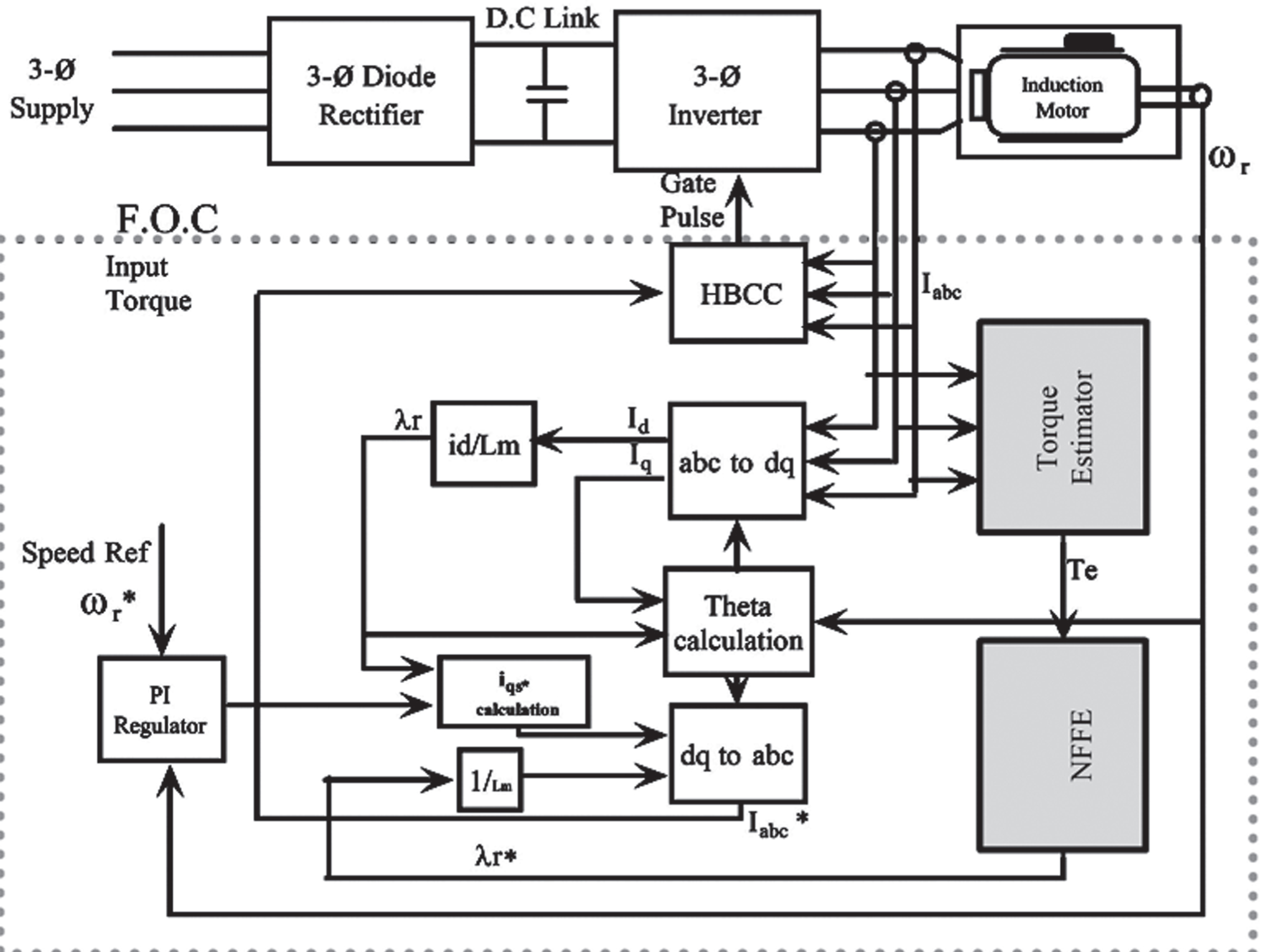
Rotor flux vector-controlled scheme using NFFE.
The role of estimator is very important because motor parameters in general vary during the operation which further leads to malfunctioning of the drive. The value of flux at which motor is operated is based on current value of torque.
Vector control method uses the dynamic d-q model of induction motor drive. In this technique induction motor is represented in a synchronously rotating reference frame. The input currents to the machine d-q model are first converted to synchronously rotating frame by the unit vector component [22]. Stator current equations for a d-q model of squirrel cage type induction motor with synchronous reference frame are expressed as:
The electromagnetic torque (Te) developed in the motor is given by:
The power losses largely affect the efficiency of induction motor during light load and variable speed operations. Further torque and size are also important factors in deciding the IM application along with power. The output power of IM increases linearly with speed as the supply frequency increased, e.g. output power increases approximately by 20% while changing the frequency from 50 to 60 Hz. Further stator copper losses are dominant, particularly in 0.75 kW to 375 kW sized induction motors. These losses are constant irrespective of supply frequency at constant torque operation, but in case of electric vehicle the torque is variable and requires proper frequency selection. A difference of 2.5% in efficiency is observed for 60 Hz frequency instead of 50 Hz [23, 24].
The stator and rotor copper losses according to the International Electrotechnical Commission (IEC) norm [25, 26] are given as follows:
Using Equations (1) and (2) and vector control conditions, Equation (7) becomes,
Core loss can be expressed as:
In vector control strategy the stator flux can be expressed as:
Using Eq. (10) and vector control condition, the Eq. (9) becomes,
The total losses can be expressed as:
In an electric vehicle induction motor requires continuous operation and may not be interrupted to determine the losses and efficiency. Further installation of a permanent torque sensor is expensive and bulky. Thus, economic monitoring of joint condition and energy prediction techniques play an important role in induction motors [27]. The torque meters and torque estimation algorithms provide effective alternative to these issues and motivates researchers to develop efficient estimation methods. Torque developed in the induction motor can be evaluated using stator current vector (Eqs. 5 and 6), which serves as input to field-oriented control of IM.
The load torque can be calculated from the electrical torque by subtracting the friction factor of induction motor drive. The friction factor is ωeb, where ωe is speed and b = 0.005767 is the friction coefficient [28]. the estimated and load torque of the drive are shown in Fig. 2.
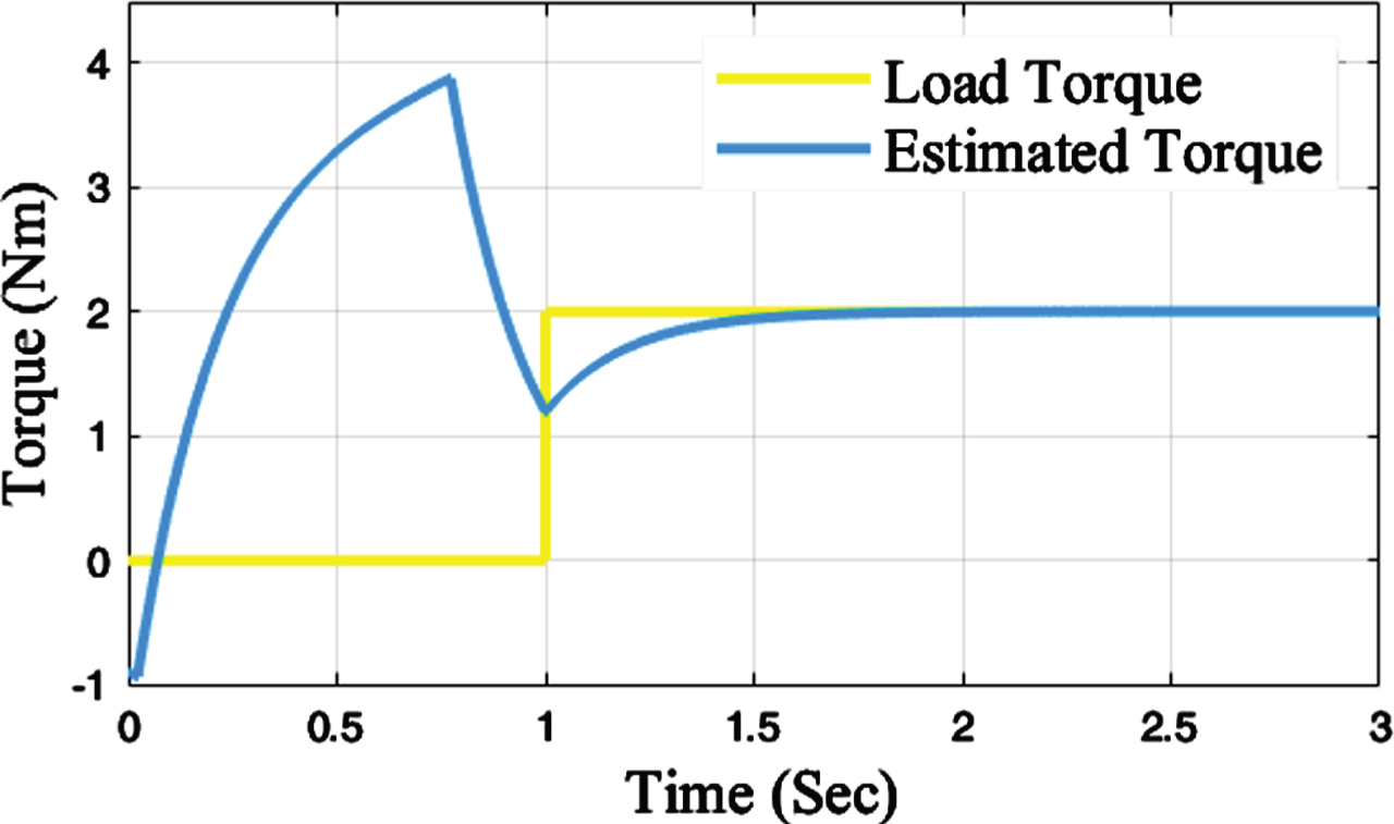
Estimated and load torque profile.
An electric motor provides high efficiency if it runs at optimal operating point i.e. copper and core losses are minimum. This necessitates the implementation of effective control scheme to achieve the required optimal condition [29, 30]. Loss model-based methods allow the IM to operate at optimal rotor flux and the required balance between losses is restored in an unpredictable operating condition. In this work, model-based algorithm is used to ensure optimisation of efficiency. The parameter variations during different operating conditions may lead to non-optimal operation, therefore a neuro fuzzy inference system is proposed.
The losses may be minimized analytically, by differentiating the loss function (Eq. 12) with respect to rotor flux. Thus, rotor flux value at which the power loss is minimum can be obtained as:
The motor parameters are generally taken to be constant while evaluating flux for minimum losses. The stator and rotor resistances are varied from nominal value to 200%, which provides different values of losses. The different values of torque required for these losses are evaluated using Eq. (15). Thus 200 pairs of rotor flux and torque are generated for training the rotor flux estimator.
Essentially, a fuzzy logic system comprises transformation of crisp values to linguistic (fuzzification), inferring the decision as per defined rule-base (decision making) and conversion of linguistic results to crisp value (defuzzification) as shown in Fig. 3 [31]. In this work, Mamdani inference system is used to design fuzzy logic-based rotor flux estimator. The IF-THEN rules are defined as:
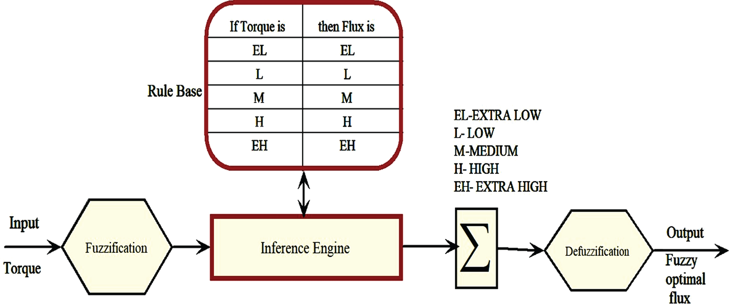
Structure of fuzzy logic system.
Rule k: if T is S1(k), Then ψ is R1(k), (k = 1,2, ... 5)
where S1(k) is the fuzzy linguistic set for input and R1(k) is the fuzzy linguistic set of output. Five rules are formulated on the basis of flux and torque data acquired from analytical method of decision making. In this work bisector method is used for defuzzification to compute the final output. The defuzzified value may be expressed as:
The triangular membership functions selected for input and output fuzzification are shown in Fig. 4.
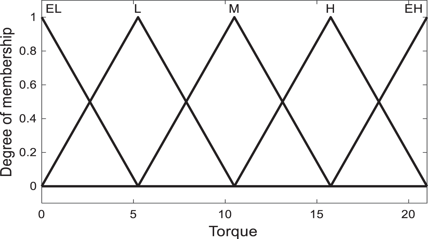
Membership function of Torque.
It is observed from the results that FLFE provides approximate flux value for various operating conditions of the vehicle as fuzzy inference system is not designed optimally. Therefore, to obtain accurate flux values the parameters of fuzzy logic membership functions are trained using the artificial neural network which leads to neuro-fuzzy flux estimator.
In a fuzzy inference system, the designer decides the membership functions and rule base using knowledge base of the plant. However fuzzy logic system shows efficient performance only when it is designed using some optimizing algorithm. Therefore, a Neuro-Fuzzy Flux Estimator (NFFE) based on adaptive neuro-fuzzy inference system (Fig. 5) is suggested for estimating rotor flux in partially loaded induction motor. The membership functions of the fuzzy inference system are designed using artificial neural network. The algorithm uses hybrid learning algorithm which is a combination of backpropagation gradient descent and least-squares methods [32, 33]. The fuzzy inference system has an input x and output y. The rule base comprises of five fuzzy rules. If x is A1, then f1 = P1x+r1 If x is A2, then f1 = P1x+r2 If x is A3, then f1 = P1x+r3 If x is A4, then f1 = P1x+r4 If x is A5, then f1 = P1x+r5
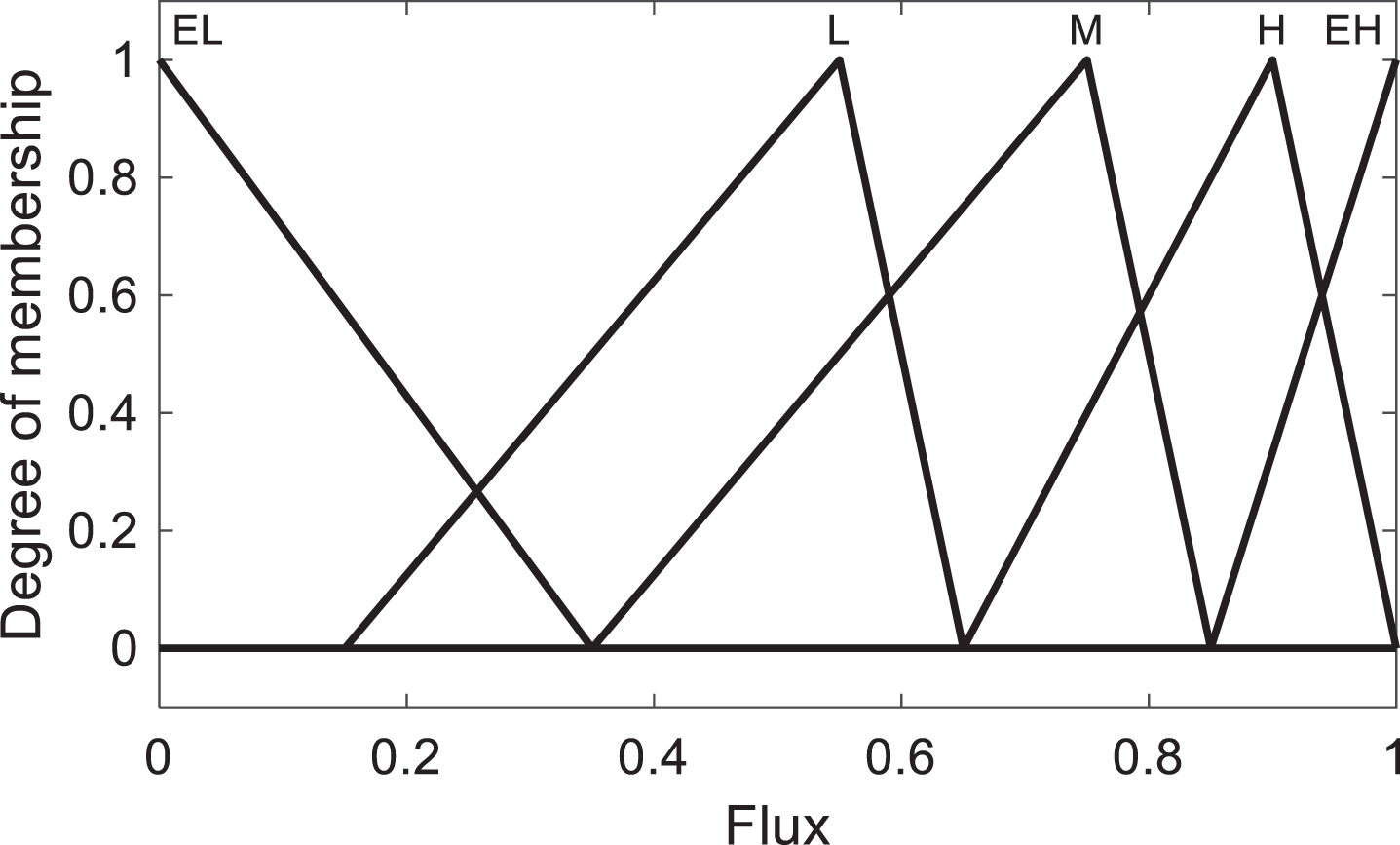
Membership function of Flux.
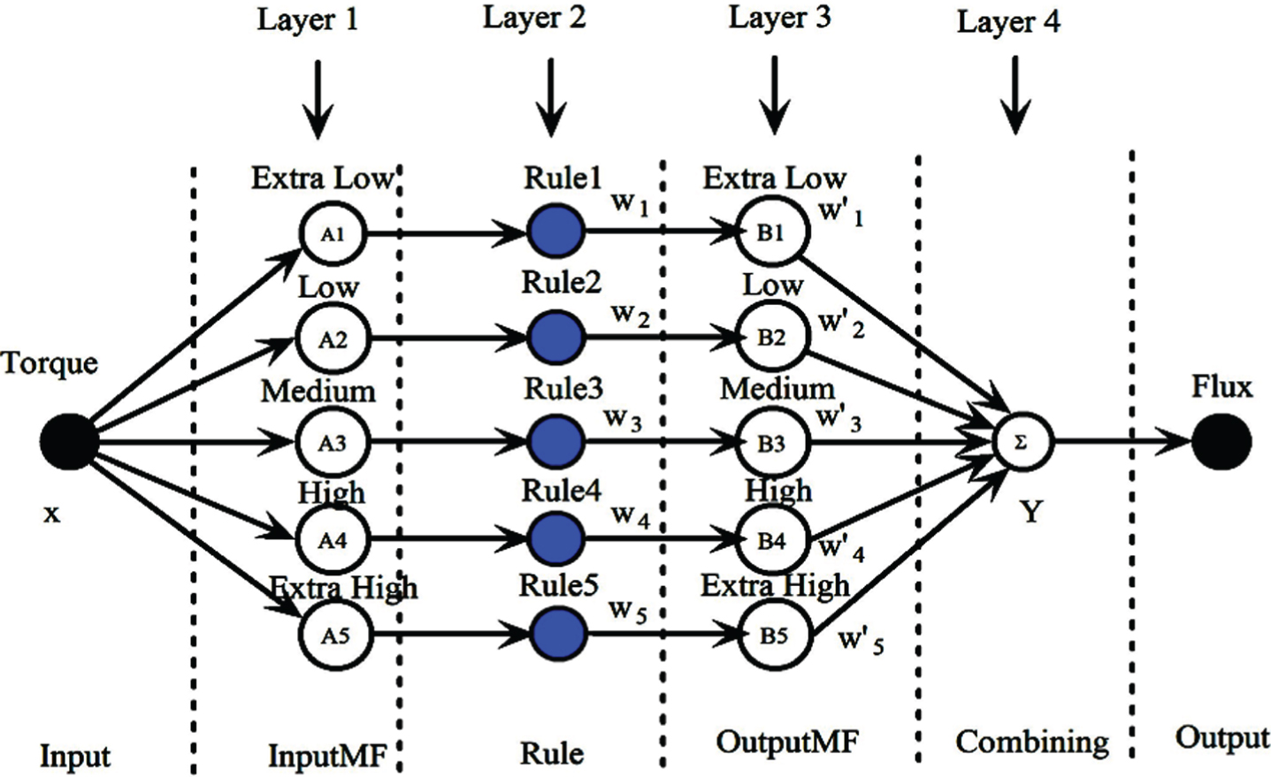
ANFIS structure.
Layer1: This layer defines the input membership function, where every node k is a fixed node defined as:
Layer2: Layer 2 represents the rule base of fuzzy logic system. The incoming signals to this layer are multiplied and product is the output.
Constant 1 is considered to express direct relationship between wi and Ak.
Layer3: This layer is also a fixed node and output is a function of rules and input membership function.
Layer4: This layer computes the overall output as summation of all incoming signals.
A dataset of 200 samples is generated by simulating the drive on various real-time conditions, thus considered samples represent the complete range of operation. The adaptive neuro fuzzy inference system is trained using 80 % samples i.e. 160 and 20 % i.e. 40 samples are used for testing. The trained estimator is then used to evaluate the rotor flux for induction motor under variable loading and uncertain conditions.
The induction motor and estimator model are simulated in MATLAB on Intel core i5 processor 1.6 GHz 8 GB of DDR4 RAM. Initially FIS structure is created with 5 membership functions of input and output variables which provides zero error tolerance. In the beginning, error is very large which then decreases in the successive epochs. As the desired RMSE is very small as compared to RMSE in the beginning, it seems from the plot that after 100 epochs error is not decreasing. However, the training and testing error at 100 epochs are 0.002472 and 0.0033 which are reduced to 0.002205 and 0.0028307 respectively after 1500 epochs. The performance of the system is not good if training is terminated before 1500 epochs. The training results are shown in Fig. 6.
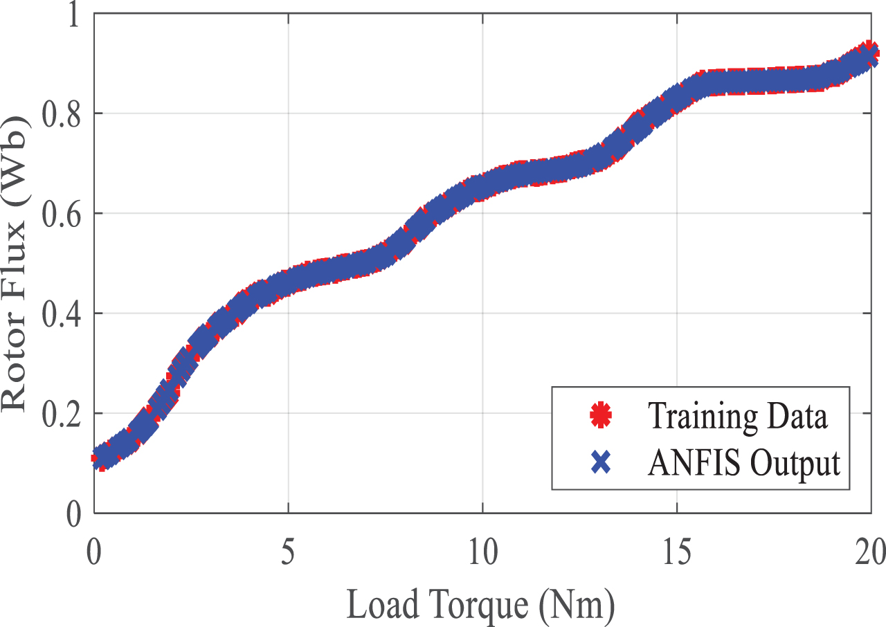
(a) Training of data set with 1500 epochs.
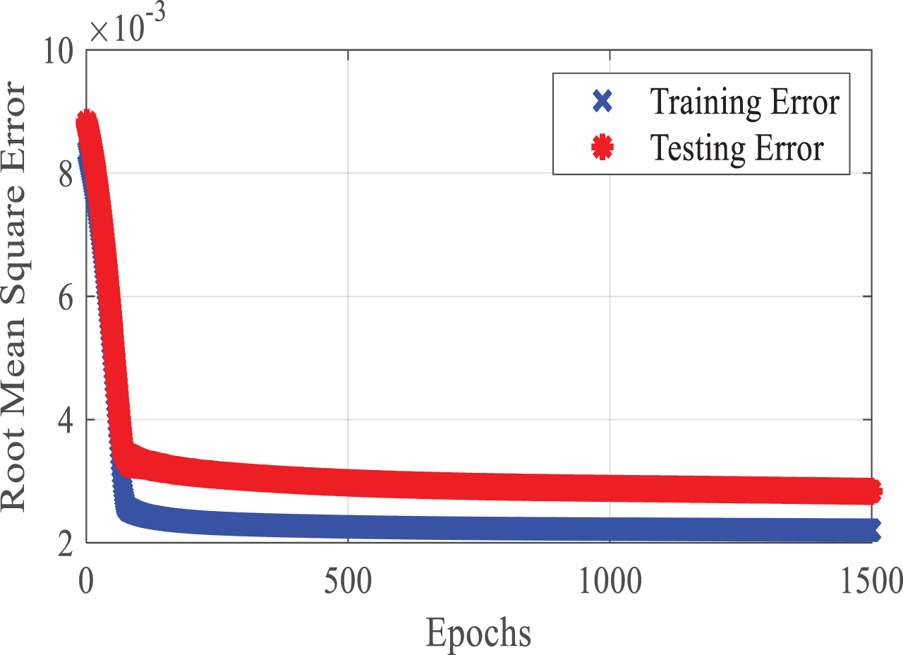
(b) RMSE with 1500 Epochs.
Step size also play a crucial role in training. A larger step size provides fast convergence, however beyond a certain limit it shows large training error. The step size for optimum training must increase in the beginning and later on it should decrease.
A three-phase induction motor of 5HP, 460 V, 60 Hz is considered for the present analysis. The motor parameters considered in this work are listed in appendix A. The rotor flux of induction motor is optimized so as to minimize the losses under different realistic operating conditions. The analysis is carried out for varying load and motor parameters.
Variation in load
The induction motor is operated at constant speed and varying load torque. The analytical, fuzzy logic flux estimator and neuro-fuzzy flux estimator are used to provide suitable flux for the full, half and quarter load torque conditions. Figure 7 shows the variation of losses and rotor flux at different loads. It is observed that with the decrease in load torque rotor flux decreases. It is also observed that NFFE provides the most suitable rotor flux estimation in comparison to analytical and FLFE methods. Table 1 shows the induction motor losses for variable load conditions. It is observed from the results that NFFE reduces the losses in comparison to other designed schemes leading to large power savings.
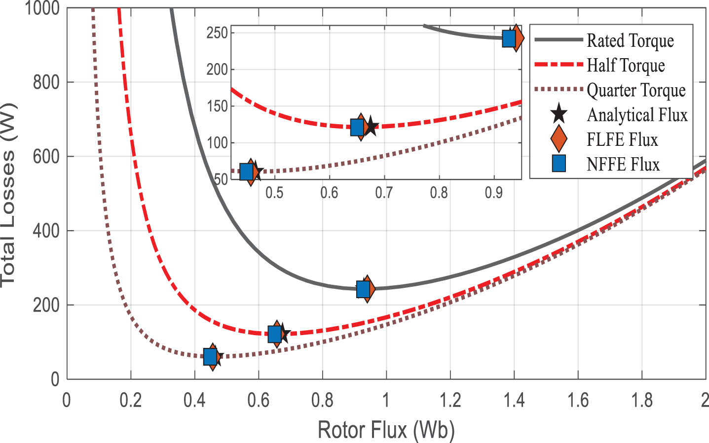
Loss function curve and minimum rotor flux at rated speed.
Variation of losses for different load profiles
Efficiency of drive for variation in stator and rotor resistances
The parameters of motor generally change during the normal operating conditions. Therefore, in order to analyse the effectiveness of designed scheme, stator and rotor resistances of induction motor are varied at rated speed and torque. The stator and rotor resistances are varied individually from nominal value to 200% at full load torque.
The effects of variation in stator and rotor resistances on power losses for different loading conditions are shown in Fig. 8(a) and 8(b) respectively. It is inferred from the results that stator resistance is more dominant as compared to the rotor resistance. Critical analysis is also done by varying both the resistances simultaneously up to 150% each and the obtained results are shown in Table 2. It is observed from the results that increase in resistances increases the rotor flux in case of analytical method, which in turn increases the power losses. However, FLFE and NFFE based rotor fluxes are constant leading to less power losses. Further NFFE provides considerable saving in losses as compared to FLFE.
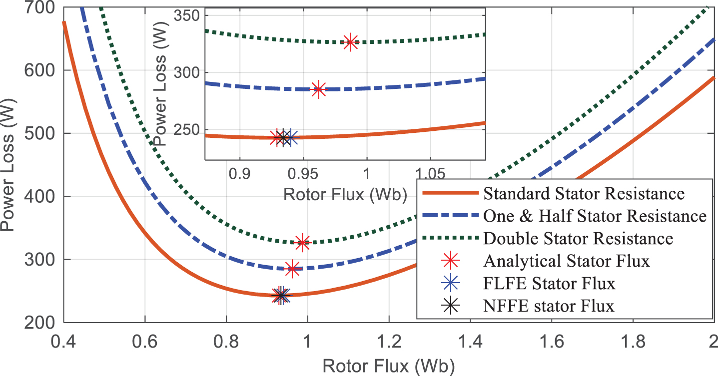
(a) Variation in losses and optimal flux for different values of stator resistance.
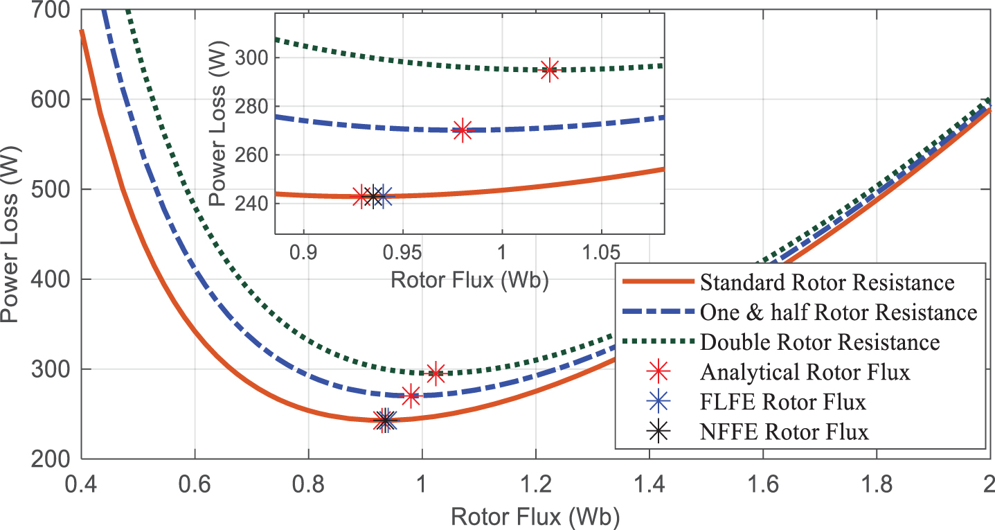
(b) Variation in losses and optimal flux for different values of rotor resistance.
Figure 9 shows the variation of motor efficiency for standard resistances and 150% change in standard resistances. It is also inferred from the results that increase in motor resistances cause heating and thus efficiency is reduced. The efficiency of the drive with constant nominal flux for 1.5 times of the rated stator and rotor resistance is 91.94 % and 92.66 % respectively whereas the efficiency for FLFE is 93.55% and that of NFFE is 94.51%.
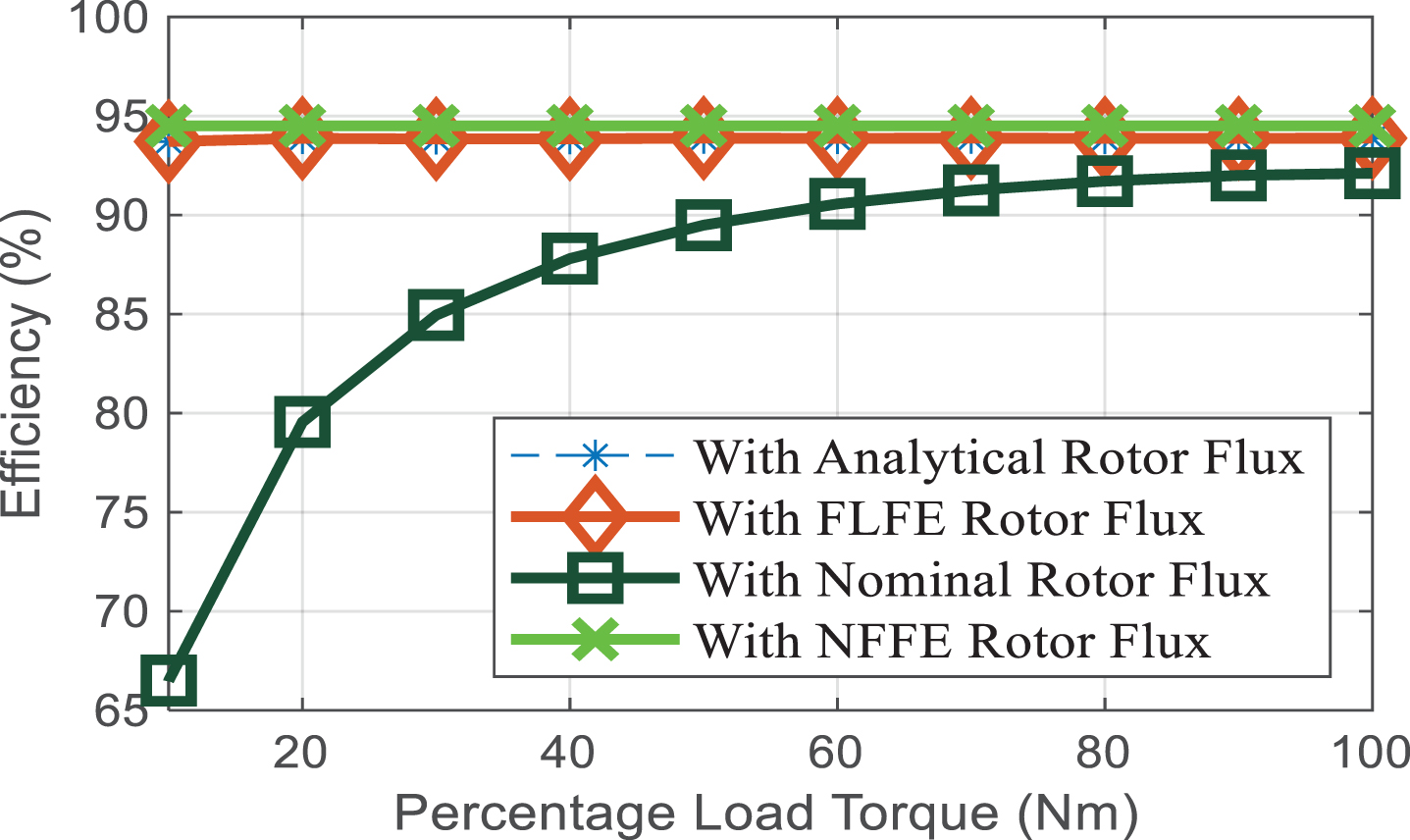
(a) Efficiency curve for standard stator and rotor resistances.
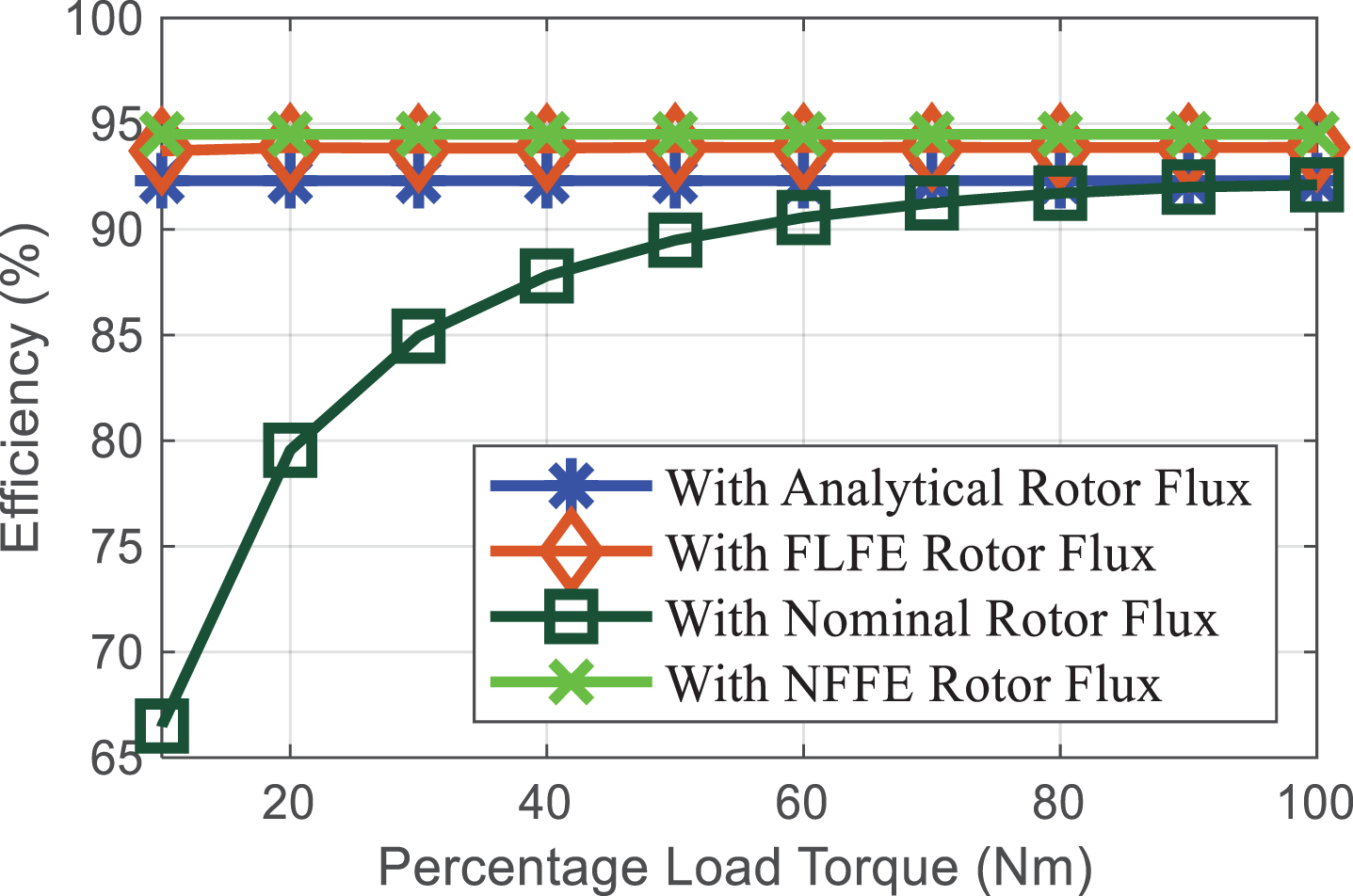
(b) Efficiency curve for 150% change in stator and rotor resistances.
The presented three methods are simulated for indirect vector control of induction motor on Simulink/MATLAB.
The drive is run for 3 seconds at 1500 rpm and 2Nm load torque. The steady state is achieved at 0.775 seconds and load torque is applied to the drive at 1second. Figure 10 shows the comparison of efficiency obtained using the designed control schemes. Results reveal that NFFE provides significant improvement in drive efficiency as compared to other considered techniques. Therefore, it is obvious from the above analysis that neuro-fuzzy based estimator minimizes the losses and handles the uncertainties efficiently by providing optimal rotor flux under partial loading conditions.
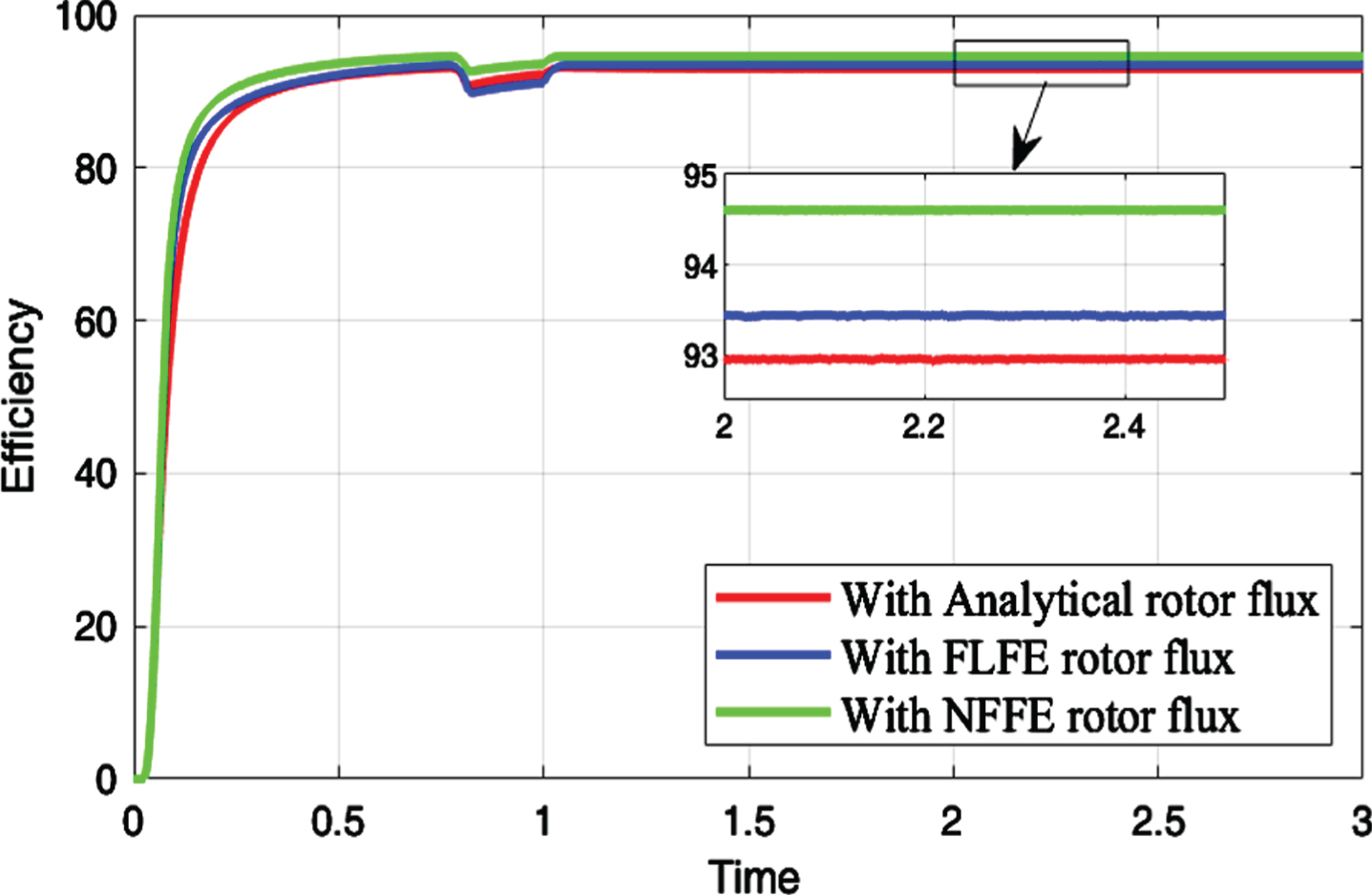
Drive efficiency for different control schemes at 2Nm load torque.
In this research work, an optimal rotor flux estimator is designed for loss minimization of induction motor used in electric vehicles. The reduction of flux reduces the losses and hence increases the efficiency under partial loading conditions. A neuro-fuzzy flux estimator is proposed for the purpose. The estimator is an adaptive neuro-fuzzy inference system in which membership functions are trained using artificial neural network. Fuzzy logic flux estimator and analytical method are also used for comparative analysis. The estimators are trained using the torque vs. rotor flux data generated analytically. It is observed from the results that NFFE effectively handles uncertainties in motor parameters and provides the most suitable rotor flux in comparison to other techniques under consideration. It is also revealed from the results that efficiency of the induction motor is increased under partial loading conditions. Thus, it is concluded that neuro-fuzzy scheme proves to be an efficient and robust estimator for rotor flux of induction motor under partial loading conditions.
Footnotes
Appendices
Drive parameters
| Parameter | Value |
| Stator resistance (Rs) | 1.115 Ω |
| Rotor resistance (Rr) | 1.083 Ω |
| Stator inductance (Ls) | 0.209 H |
| Rotor inductance (Lr) | 0.209 H |
| Mutual inductance (Lm) | 0.203 H |
| Pole (P) | 4 |
| Hysteresis constant (Kh) | 1.9×10⁻⁵ |
| Eddy current constant (Ke) | 3.2×10⁻³ |