
Abstract
Regarding the increasingly severe energy crisis and environmental issues, a dynamic control of the charging and discharging of electric vehicles into the grid that is universally adapted to optimal control is proposed in this study. When the charging control system is based on the load function of the current distribution network, the electric vehicles connected to the charging station are charged and deployed, and the best fuzzy control is adopted to calculate the electric power to be transmitted to each charging hub, so as to improve the load characteristics of the regional grid to reach the grid The highest efficiency of use. Finally, after repeated trials and studies, the orderly charging and deployment system when meeting the charging requirements of electric vehicles, the load of electric vehicles can exert its flexibility.
Keywords
Introduction
Faced with increasingly severe energy crisis and environmental problems, high-energy, high-emission fuel vehicles will be replaced by low-energy, zero-emission, and low-noise electric vehicles. This has become the trend of modern society development [7, 12]. As an emerging clean, efficient and intelligent transportation tool, electric vehicles have huge development potential and broad application prospects [3, 9]. With the widespread application of electric vehicles and the progress of battery technology, the V2G (Vehicle-to-Grid) technology of electric vehicles into the grid has attracted more and more attention [1, 4]. The core of V2G is to use the energy storage resources of a large number of electric vehicles as a buffer for the grid and new energy under the premise of meeting user needs [15]. The V2G system has the functions of providing power regulation, peak shaving and valley filling, frequency regulation and other auxiliary services to the grid, which can effectively improve the operation efficiency and stability of the grid. stability of the grid [2, 12]. At present, the key issues involved in V2G technology are mainly divided into two categories: The first category is how to formulate reasonable and effective dynamic control for orderly charging and discharging control of electric vehicles, and reasonable arrangement of charging plans can not only meet the charging needs of electric vehicles, but also The grid provides auxiliary services; the other is how to control the V2G two-way converter to realize the conversion of electric energy and the most two-way flow of energy [10, 14]. A reasonable and orderly charging and discharging strategy and a V2G converter control strategy are the keys to the realization of V2G technology. Both are indispensable. The orderly charging and discharging strategy can realize auxiliary functions such as peak shaving and valley filling and frequency adjustment of charging vehicles, while the V2G converter control strategy can provide the underlying support for V2G, realize the conversion of electric energy and the two-way flow of energy between electric vehicles and the grid [11, 13]. At present, there have been many research results on the control strategy of V2G converters. This article mainly focuses on the dynamic control of the V2G management system [5, 6].
This article first introduces the composition and relationship of the V2G management system, including the scheduling system and the V2G converter system; then, a V2G charge and discharge control strategy based on adaptive optimal fuzzy control is proposed, which uses an adaptive optimal fuzzy control algorithm Adjust the charge and discharge power of newly connected electric vehicles according to the current supply and demand situation of the power grid and the state of charge of the connected electric vehicles. Numerical example simulation shows that the orderly dynamic control proposed in this paper can achieve the auxiliary function of cutting bees and filling the grid under the premise of meeting the needs of electric vehicle users, and at the same time can avoid the excessive number of electric vehicles connected to the grid when the grid load is low. This leads to a new load spike.
V2G management system
The V2G management system mentioned in this article is shown in Fig. 1. It is composed of an orderly charging scheduling system and a V2G converter control system. The former is the upper optimization scheduling layer, responsible for managing the power distribution of charging piles in a certain area. The main responsibilities are Reasonably arrange the charge and discharge power of each charging pile, improve the load characteristics of the regional grid, and realize the auxiliary function of peak shaving and valley filling; the latter is the lower real-time control layer, responsible for controlling the actual charging and discharging behavior of each charging pile, and the main responsibility is to respond The power commands issued by the dispatch system are used to control the actual charging and discharging behavior, and provide a stable interface for electric energy conversion and energy flow. Among them, the orderly charging and discharging scheduling system issues power reference commands for the charging pile converter control system, and the V2G converter control system responds to power commands to control the actual charging and discharging behavior.

V2G management system.
The orderly charging dispatch system collects the power output data load data of the current distribution network and the load data of the connected electric vehicles reported by each charging pile, calculates the charging and discharging power of each charging pile connected to the electric vehicle, and sends it to each charging pile. After the V2G converter system receives the power command issued by the upper scheduling system, it controls the electric vehicle to perform orderly charging and discharging, thereby controlling the actual charging and discharging behavior.
The overall control process of the V2G management system is as follows:
(1) The orderly charging dispatch system collects the electric vehicle data that each charging pile has been connected to in the current period, and at the same time obtains the power generation information and load information of the power grid during the period from the regional power grid dispatch center;
(2) The orderly charging dispatch system calculates the electric vehicle’s electric demand, the allowable discharge capacity and the latest charging time based on the electric vehicle charging data, and considers the current power supply and demand situation of the grid, calculates the electric vehicle’s reference charging and discharging power, and downloads Distributed to each charging pile;
(3) The V2G converter control system of each charging pile performs actual charging and discharging control according to the issued charging and discharging power commands, and provides a stable electric energy conversion and energy exchange interface.
The orderly charging dispatch system is responsible for managing the charging and discharging power of electric vehicles at each charging pile in the regional distribution network, integrating the load characteristics of the current period of time, and calculating and issuing the charging and discharging power commands of each charging pile electric vehicle to improve the regional load Features, realize the auxiliary function of peak shaving and valley filling.
Taking into account the randomness of electric vehicle access, the accurate access time and charging demand of future electric vehicles cannot be predicted. Therefore, this paper divides 1d into 288 time periods, each time period is 5mjn, and the operating state of the power grid is updated at the beginning of each time period, which is the operating calculation point of the dispatching system, as shown in Fig. 2. If the arrival time of the electric vehicle is in the middle part of the time period, the electric vehicle needs to wait for unified charge and discharge control in the next time period.

Schematic diagram of control period.
The orderly charging scheduling system is mainly divided into a metering part and a decision-making part, and each part will be introduced separately below.
When an electric vehicle is connected to a regional charging station, you can get the type of electric vehicle connected to the charging pile (DC/AC charging pile), the time T1, the initial state of charge SOC0, and the departure time set by the user. The metering unit can calculate the required charging power Qc and the allowable discharge Qd of the connected electric vehicle, as shown in equations (1) respectively.
Among them, Q is the capacity of the electric vehicle battery; SOC is the current state of charge of the electric vehicle battery; SOCmax and SOCmin are the upper and lower limits of the battery during the charging and discharging process of the electric vehicle. Generally, SOCmax = 1, SOCmin = 0.2.
At the same time, in order to meet the charging requirements of electric vehicles, so that the electric vehicles are fully charged before they leave, the latest charging time of electric vehicles is defined as T3. Before this time, the electric vehicle is in a dispatchable state, which can be charged and discharged. After this time, the electric vehicle is charged with the rated charging power. Since the charging and discharging state of electric vehicles in the future cannot be predicted, the charging time T is replaced by the longest charging time of electric vehicles, and the time margin of electric vehicle charging is defined as k, the calculation formula of T3 is:
Among them, T is the longest charging time required for the electric vehicle to charge from SOCmin to SOCmax with the lowest charging power, and its expression is shown in equation (3); k is the current state of charge SOC of the electric vehicle battery and the expected SOCmax, Residence time and other factors, the smaller the k, the more sufficient the charging time of the electric vehicle, the expression is shown in equation (4).
The value range of the above is (1, 3); Pmin is the minimum charging power of electric vehicles.
The core idea of the decision-making part is: when the grid is at a peak load, a large number of electric vehicles will inevitably increase the burden on the grid. If the electric vehicles are in a dispatchable period at this time, the electric vehicles can be controlled to reduce the electric energy absorbed from the grid, and even control Electric vehicles inject electric energy into the grid; when the grid is at a low load, the electric vehicles can be controlled to increase the electric energy absorbed from the grid and improve the efficiency of the grid. At the same time, during the dispatchable period, the charging power of electric vehicles is related to the demand of electric vehicles. When the demand for electric batches is high, the electric vehicles can be charged with higher power; when the demand for electric batches is very low, in order to prevent excessive When charging, the charging power should be at a low level.
From the above analysis, it can be seen that the charging and discharging power of electric vehicles is related to the current electric power and grid load conditions of electric vehicles, and it is difficult to describe with analytical models. The adaptive optimal fuzzy control is based on people’s operating experience of the controlled object, without knowing the internal structure of the controlled object and its analytical model, and its robustness and adaptability can meet the control requirements. Therefore, the decision-making part adopts the method of adaptive optimal fuzzy control. According to the current supply and demand of the grid and the state of charge of connected electric vehicles within the dispatchable period, the charging and discharging power of electric vehicles can be independently adjusted, while meeting user needs, Participate in grid peak shaving and valley filling.
Set ΔP as the power shortage of grid generation and load, the basic domain is set to [–100,100]kW, the fuzzy domain is {-3, - 2, - 1, 0, 1, 2, 3}, and the quantization factor K1 = 3/100, the corresponding fuzzy subset is {NB g , NM g , NS g , ZE g , PS g , PM g , PB g }. Among them, the fuzzy subset ZEg indicates that the power balance is 0, and the current grid supply and demand is in balance; the fuzzy subset NBg indicates that the current grid’s power shortage is very high, and it is at a peak of electricity consumption; the fuzzy subset PBg indicates that there is a lot of electricity generated by the current grid, At this time in the low electricity consumption; fuzzy subsets NMg, NSg, PSg, PMg respectively represent relatively insufficient, insufficient, sufficient, and very sufficient power generation products.
Set Qc as the power demand of electric vehicles. The basic domain is set to [0,Q], the fuzzy domain of electric vehicles is {0, 1, 2, 3, 4, 5}, the factor K2 = 6/Q, and the corresponding fuzzy subset is {Z c , VS c , S c , M c , B c , VB c }. Among them, the fuzzy subset Zc indicates that the charging demand of electric vehicles is close to 0, and the battery is almost full at this time; the fuzzy subsets VSc, Sc, Mc, and Bc respectively indicate that the charging demand of electric vehicles is very low, low, high, and high; The fuzzy subset VBc indicates that the charging demand of electric vehicles is extremely high, and the battery power is very low at this time. The allowable discharge capacity of electric vehicles Qd is similar to Qc, the basic domain is set to [0,Q], the fuzzy domain is {0, 1, 2, 3, 4, 5}, the quantization factor K2 = 6/Q, the corresponding fuzzy The subset is {Zd, VSd, Sd, Md, Bd, VBd}. Among them, the meaning of each fuzzy subset is similar to Qc, which respectively indicate that the allowable discharge voltage of electric vehicles is very small, very low, low, high, high, and extremely high.
Under normal circumstances, the charging and discharging power of the DC charging pile can be continuously adjusted between 0 and the rated power, while the AC charging pile is open-break adjustment (that is, the power can only be 0 or the rated power). Therefore, different fuzzy strategies should be adopted for electric vehicles connected to DC or AC charging piles. For DC charging piles, the basic domains of charging and discharging power are set to
The membership degrees of the input and output batches of the charge-discharge adaptive optimal fuzzy controller are described by the triangular membership function, and its mathematical expression is shown in equation (5). Figure 3 shows the membership function curve of the power deficit ΔP.
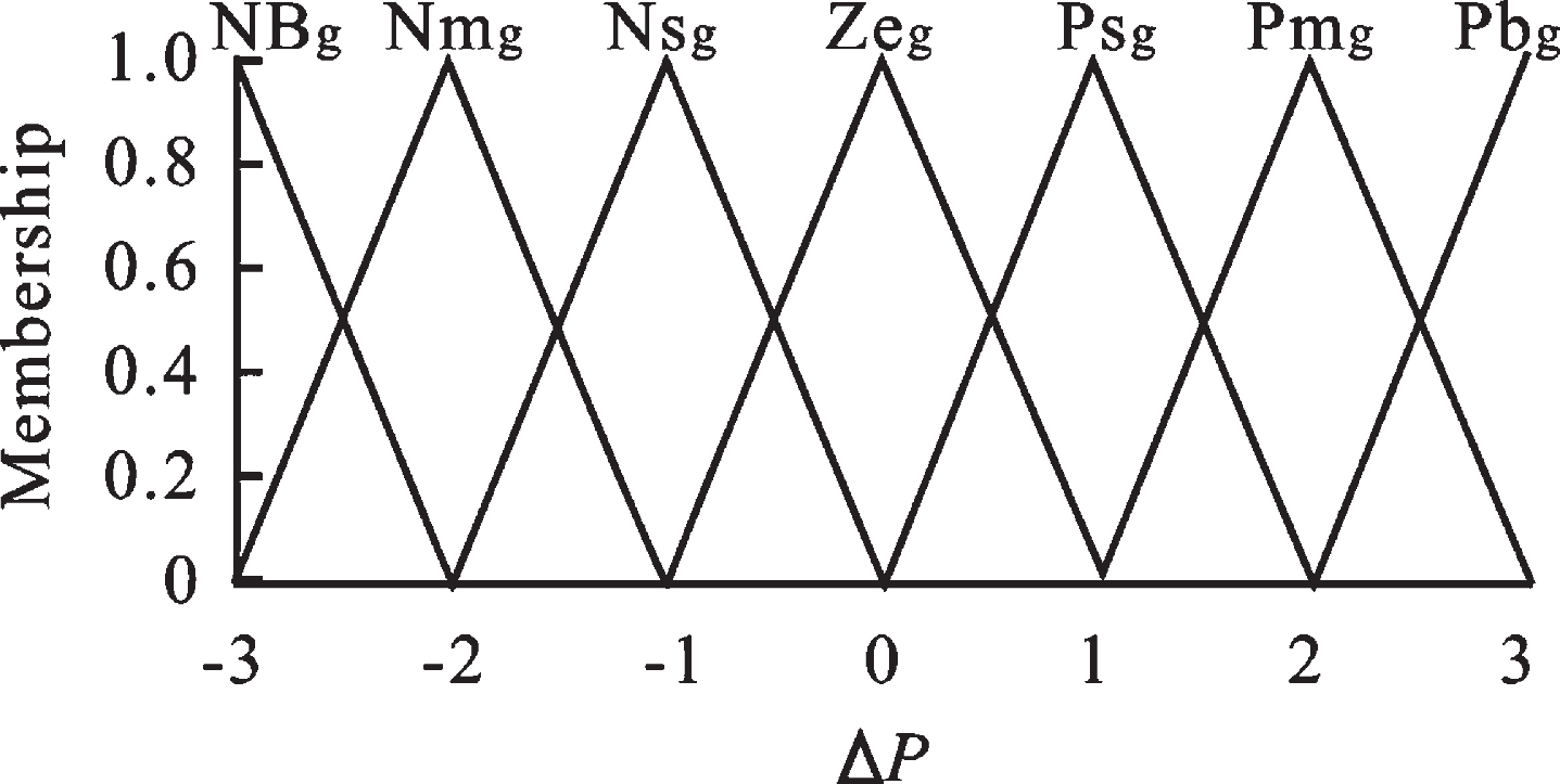
The membership function of ΔP.
Among them, the parameters a and c are the triangle “foot”; the parameter b is the triangle “peak”.
The result of fuzzy logic inference determines the output command of the controller, and different fuzzy logic inference rules will lead to different control effects. In this paper, two adaptive optimal fuzzy controllers are used, namely, charge adaptive optimal fuzzy controller and discharge adaptive optimal fuzzy controller. The core idea of the adaptive optimal fuzzy controller for charging and discharging is: under the premise of meeting user needs, when the load level is high, the charging power of the electric vehicle is set at a low level according to the state of charge of the electric vehicle battery. The discharge power is at a higher level to avoid more electric vehicles charging at peak power consumption and aggravating power shortage; when the load level is low, set the charging power of electric vehicles at a higher level to absorb excess electric energy.
Set pc and pd to be the charging power and discharging power of the electric vehicle respectively. The controller can be described by the above-mentioned N = 42 fuzzy rules. The output of the i-th fuzzy rule is ui, and the output expression is shown in equation (6).
Among them, uic and uid are the output results of the i-th rule in the charge and discharge controllers respectively; vic and vid are the weights of the i-th rule in the charge and discharge controllers in the total output respectively. The calculation formula is as follows (7) Shown.
Among them, xc and xd are the inputs of the charge and discharge controllers respectively;
The power command pref can be obtained by coupling the output result pc of the charge adaptive optimal fuzzy controller and the output result pd of the discharge adaptive optimal fuzzy controller, as shown in equation (8).
Among them, α is the electric vehicle discharge participation factor. If the regional grid does not allow electric vehicles to discharge, this factor can be set to 0; if the regional grid allows electric vehicles to discharge, the value of the factor can be defined according to the grid’s tolerance to discharge. The higher the value is set, the higher the degree of electric vehicle discharge. In general, the value range of α is 0.5–0.8.
Basic data of the calculation example
Figure 4 shows the total base load curve under distribution transformers in a certain area. Assume that the number of electric vehicles in the area is 500, 200 of which are connected to AC charging piles, and 300 are connected to DC charging piles. The battery capacity is 32kW·h. Assume that the rated charge/discharge power of the AC charging piles in the charging station are both 7 kW, the maximum discharge power allowed by the DC charging pile is 5 kW, and the maximum charging power is 12 kW. According to the proposed Monte Carlo method based on the electric vehicle travel chain simulation, the charging needs of electric vehicles in office areas, commercial areas and residential areas are obtained.

Basic load curve of distribution network.
Figure 5 shows the electric vehicle’s instant charging method and the load curve of the distribution network under the orderly charging dynamic control proposed in this article. It can be seen from the figure that because a large number of electric vehicles are connected to the distribution network, load spikes are easily generated in the two periods of 09 : 00–10 : 00 and 18 : 00–21 : 00, 09 : 00–10 : 00 The reason for the load peak during the period is that a large number of electric vehicles drive into the charging station near the work place for charging, and the reason for the load peak during the 18 : 00–21 : 00 period is that a large number of electric vehicles drive into the charging station near the residence. Recharge. At the same time, these two periods are also peak periods of load power consumption within a day, and the connection of a large number of electric vehicles has also exacerbated this load peak. After adopting the orderly charging dynamic control proposed in this article, it can be clearly seen that on the premise of meeting user needs, the charging demand of electric vehicles connected during the peak load period is postponed to the low load period, low power consumption at noon and power consumption at night The load demand during the trough period has increased significantly. This strategy can make full use of the power grid and make the load curve trend more stable, which is beneficial to the stable operation of the grid.

Distribution network load curve under 2 strategies.
In the instant charging mode, the electric vehicle is charged immediately after arrival and stays in the station after being fully charged, which does not make full use of the “distributed energy storage” feature of electric vehicles. Figure 6 shows the state-of-charge change curve of partially connected electric vehicles under the orderly charging dynamic control proposed in this article. It can be seen from Fig. 6 that due to differences in the types of charging piles used to connect electric vehicles at different times, the current distribution network conditions, charging requirements, and staying time, the orderly charging scheduling system arranges different charging plans., But they can effectively use the idle time of electric vehicles to complete the charging task within the specified stay time.

The state-of-charge curve of some electric vehicles.
Based on Figs. 5 and 6, it can be seen that the electric vehicles under dynamic control proposed in this article are charged/discharged with appropriate charging/discharging power within a schedulable time period, which not only prevents the electric vehicle from being idle for a long time, but also The power grid provides services for peak shaving and valley filling.
The running time of the dynamic control simulation model proposed in this paper is only 73.6 s. Compared with the 288 periods of Id, the average time per period is only 0.256 s, which is less time. Therefore, it is suitable for online control of large-scale electric vehicles. The article presents the electricity price situation at each time period, as well as the charging cost and maximum peak-valley difference of electric vehicles under different strategies. The electric vehicles under the control strategy proposed in this article rarely produce charging behavior during peak load. The charging time of electric vehicles connected to the peak load period is delayed to the period of low load, thus reducing the charging cost to a certain extent; The maximum peak-to-valley difference under the proposed control strategy is significantly reduced, and the load curve trend is more stable, which is conducive to the stable and economic operation of the power grid. Therefore, the control strategy proposed in this paper not only effectively reduces the user’s charging cost, but also effectively reduces the grid peak-to-valley difference, which is a two-way beneficial strategy.
Conclusion
V2G technology is the current research hotspot. This article first builds the V2G management system architecture, and then from the optimization scheduling level, studies the orderly charging and discharging dynamic control of electric vehicles aimed at suppressing the grid peak-valley difference and reducing the charging cost, and proposes The strategy is verified, and the simulation results show that the electric vehicle charging and discharging scheduling model based on the adaptive optimal fuzzy control algorithm proposed in this paper has high resource utilization, optimized calculation speed and high operating efficiency for electric vehicles, and is suitable for large-scale The organization of electric vehicle access; consider that the first connected electric vehicle changes the power shortage state of the grid after the charge and discharge power control, and then affects the subsequent access to electric vehicle control problems, and overcomes the problems in the literature. It can consider the insufficiency of the electric vehicle connected first on the subsequent dispatch control.
Footnotes
Acknowledgments
Innovation training project of college students in Jilin Province, No: 202013604001.