
Abstract
Since the BP neural network has poor performance and unstable learning rate in the maximum power point tracking (MPPT) algorithm of photovoltaic (PV) system, an adaptive particle swarm optimization BP neural network-fuzzy control PV MPPT algorithm (APSO-BP-FLC) is proposed in this paper. First, the inertia weight, learning factor and acceleration factor of particle swarm optimization (PSO) are self-updating, and the mutation operator is adopted to initialize the position of each particle. Second, the APSO algorithm is used to update the optimal weight threshold of BP neural network, where the input layer is irradiation and temperature, and the output layer is the maximum power point (MPP) voltage. Third, the fuzzy logical control (FLC) is employed to adjust the duty cycle of Boost converter. The inputs of FLC are voltage difference and duty ratio D(n-1) at the previous time, and the output is duty ratio D(n). Moreover, D(n-1) is optimized by |dP/dU| to improve the search range of FLC. The irradiation, temperature and MPP voltage of PV cell are adopted as the datasets for simulation in a city in Shaanxi province, China. Simulation results show that the proposed MPPT algorithm is superior to the APSO-BP, FLC and perturbation and observation (P&O) algorithm with tracking performance, steady state oscillation rate and efficiency. In addition, the efficiency of proposed MPPT algorithm is improved by 0.37%, 6.2%, and 6.8% as compared to APSO-BP, FLC and P&O algorithm.
Keywords
Introduction
With the conventional fossil fuel reserves are decreasing year by year, various countries have begun to promote renewable energy sources [1–3]. Since the PV power generation has the characteristics of non-pollution, omnipresent and less maintenance costs [4]. Hence, it is widely used in various fields. PV cell has strong nonlinearity and the efficiency is highly affected by the irradiation and temperature. Therefore, in this case, it is urgent to develop an simple structure and strong applicability MPPT algorithm [5].
Currently, traditional MPPT algorithm mainly includes pseudo MPPT algorithms, such as short-circuit current, open-circuit voltage and look-up table method. True MPPT algorithm includes perturbation and observation (P&O) [6], incremental conductance (INC) [7], adaptive perturbation and observation (AP&O) algorithm and more. Due to the low efficiency of traditional MPPT algorithm, it is not analyzed here.
P&O and INC algorithm has the advantages of simplicity and less maintenance costs, yet the tracking speed and stabilization accuracy cannot be balanced. Thus, the AP&O algorithm is proposed based on the horizontal and vertical division of P-U curve [8]. The AP&O algorithm can adjust the step size based on the distance from the MPP for implementing MPPT. However, the tracking performance and efficiency of AP&O algorithm can be still improved.
To cope with the mentioned drawbacks in conventional MPPT algorithm, soft computing MPPT algorithm has been put forward in succession. Artificial neural network (ANN) is commonly used to predict the MPP voltage and current of PV cell [9], yet it is easy to over-fitting. Flower pollination algorithm (FPA) is proposed by Dr. yang based on the pollination process of flowering plants, which has the fast convergence rate. In addition, the tracking performance of FPA algorithm is relatively poor [10]. Hence, the algorithm is seldom used in the practical application. Firefly algorithm (FA) [11] can quickly approach to the MPP by initializing the number of populations, the largest attraction and the absorption coefficient of light intensity. However, the FA algorithm is prone to data accumulation. Genetic algorithm (GA) accumulates the knowledge of search space based on the crossover and mutation process, and the MPP of PV cell is tracked by constantly updating the parent and offspring population [12]. However, it has strict requirement on the parameters of crossover and mutation rate. Particle swarm optimization algorithm [13] approximates the global and individual optimal solutions by competition and cooperation process [14, 15]. In addition, the PSO algorithm has the advantages of simplicity, fast convergence rate and low computational complexity. Therefore, this paper focuses on the PSO algorithm [16–18].
The authors of [19] have presented a large variation GA-RBF algorithm for microgrid PV system. In [20], Ouahib et al have developed an ANN-PSO algorithm to predict the MPP power and voltage of PV cell in a day. The authors of [21] have introduced an adaptive SMC and ANN technology to obtain the MPP. In [22], Ozdemir S et al have presented an ANFIS-PSO algorithm to control the Zeta chopper circuit and maximize the extracted PV power. An investigation of above publications reveals that the BP neural network has slow convergence rate, and the PSO has weak climbing speed and premature population. This provides additional motivation to develop the intelligent MPPT algorithm in the PV system.
To solve mentioned above problems, an adaptive particle swarm optimization BP neural network-fuzzy control PV MPPT algorithm (APSO-BP-FLC) is proposed and the Boost converter is selected as the carrier of PV system. The mutation operator is adopted to initialize the position and speed of each particle. Next, the inertia weight, learning factor and acceleration factor are employed to improve the search effect. Furthermore, the APSO and FLC algorithm is subsequently adopted to update the optimal weight threshold of BP neural network and eliminate power oscillation, respectively. Moreover, simulation is carried out to validate the effectiveness and feasibility of proposed MPPT algorithm.
This paper is organized as follows: The PV cell and system block diagram of proposed algorithm are introduced in Sec. 2. Related works and proposed algorithm are presented in Sec. 3. Datasets and simulation results are illustrated in Sec. 4. Finally, the conclusion and future works are given in Sec. 5.
PV power generation system
Mathematical model of PV cell
PV cell consists of constant current source, bypass diodes and resistances [23]. The output current of PV cell is calculated as follows:
Where: Rs represents the series resistance; Rsh is the shunt resistance; I is the output current of PV cell; U is the output voltage of PV cell; Iph is the photo-current; Io is the saturation current; A is the ideal parameter of diode; K is the Boltzmann constant (K = 1.38×10⁻²³ J/K); q is the Coulomb constant (q = 1.6×10⁻¹⁹ C); T is the temperature of PV cell, expressed in °C [24]. The PV cell equivalent circuit is given in Fig. 1.

PV cell equivalent circuit.
The PV cell is selected from the simulation module library (1Soltecg 1STH-215-P) in this paper. Both the number of series-parallels PV cells is 1. Table 1 shows the PV cell and Boost converter parameters. Figure 2(a) shows the P-U curve of PV cell under varying G (T = 25 °C). The P-U curve is a single-peak curve with only one MPP, and the output power varies with G and T. Figure 2(b) shows the I-U curve of PV cell under different T (G = 1000 W/m2). The I-U curve has a strong nonlinearity, and the short-circuit current fluctuates with irradiance level and ambient temperature [25]. In this context, it is necessary to use the corresponding MPPT algorithm for making the working status of PV array as close to the MPP as possible.
PV cell and Boost converter parameters

PV Characteristic curve under different G (a) P-U (b) I-U.
As shown in Fig. 3, the Boost converter is adopted as the carrier of PV system. The PV system consists of PV cell, adaptive particle swarm optimization-optimized BP neural network algorithm, fuzzy logical control and Boost converter. In this study, the APSO-BP-FLC algorithm is proposed to improve the convergence rate and reasoning ability of BP neural network.
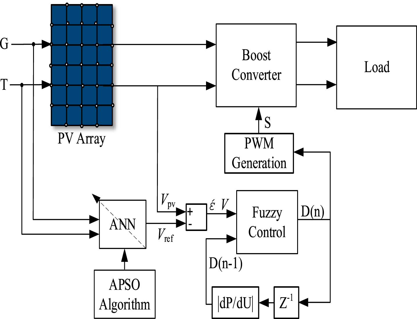
Schematic diagram of the proposed algorithm.
The main processes are as follow: First, the irradiation and temperature are sampled as the inputs of PV system. Second, the APSO algorithm is used to update the weight threshold of BP neural network. Third, the optimized BP neural network is employed to predict the MPP voltage. Next, the difference voltage (ΔV = Vpv - Vref) and duty ratio D(n-1) at previous time are used as the inputs of FLC, which obtain the duty cycle of Boost converter D(n). Moreover, D(n-1) is optimized by |dP/dU| to improve the search range. Finally, the PWM technology is adopted to control the on-off time of Mosfet Q.
ANN algorithm
BP neural network is a global approximation network, which has the advantages of simplicity, self-learning and self-adaptation. Therefore, ANN is widely used in the PV system. Figure 4 shows a typical three-layer ANN structure. W =(W1, W2, …, Wj, …, Wl) is the column vector, Wj =(Wj1, Wj2, …, Wjn) is the weight between the output layer j and the hidden layer neuron n, bn is the bias [26, 27].
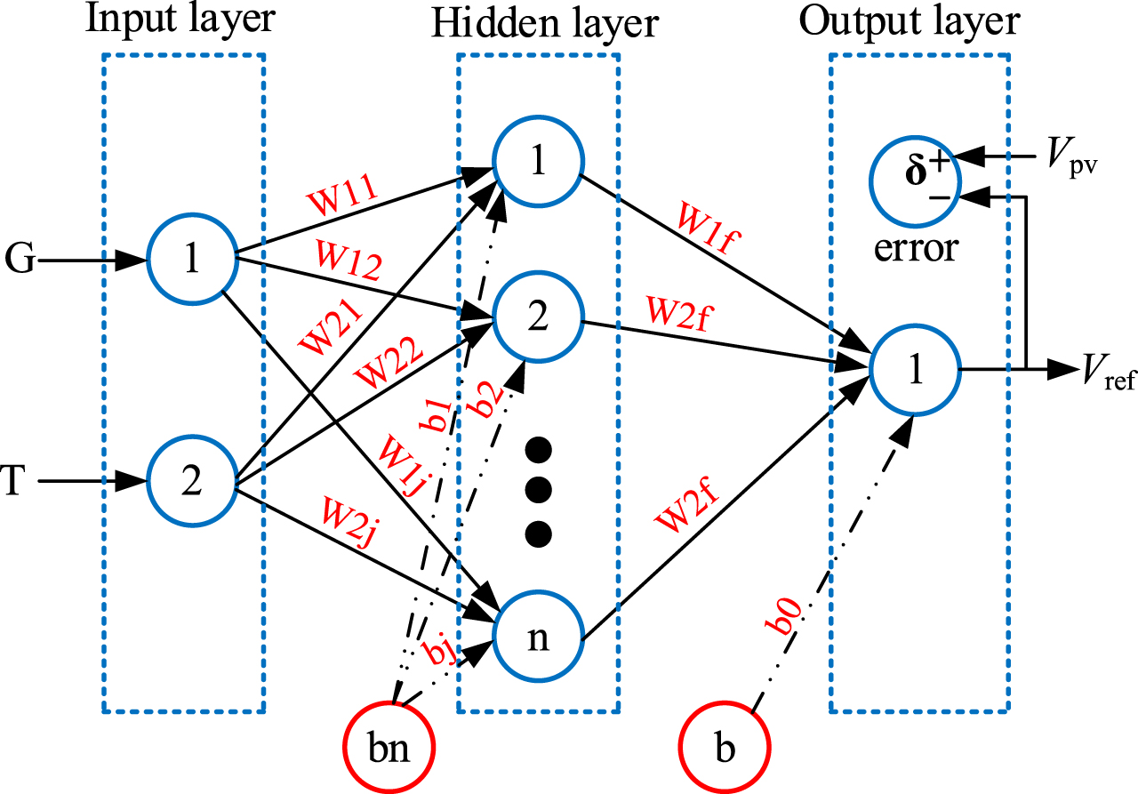
Artificial neural network.
The number of hidden layer nodes has a strong influence on the convergence rate of BP neural network in the forward propagation. If there are fewer nodes, it is difficult to store a majority number of mapping complexes; otherwise, it will lead to a longer learning time [28]. Eq. (2) is used to update the optimal number of hidden layer nodes in this study. If the actual value deviates from the expected value, BP neural network will enter the error-back propagation mode. Also, the optimal weight threshold of each layer is modified according to the error gradient descent method [29–31]. The activation function is Tansig. Eq. (3) is the the learning rate (η). In addition, the MSE function is commonly used to evaluate the performance of BP neural network. The MSE equation is shown in Eq. (4).
Where: s represents the number of input nodes; f is the number of output nodes [32]; a is an integer within [1, 20]; c1(k) is the square error gradient value of previous i iterations of BP neural network; n is the input sets; m is the output sets; Y j (i) is the true value; T j (i) is the target value.
Dr. Eberhart and Dr. Kennedy proposed the particle swarm optimization (PSO) algorithm by observing the foraging behavior of birds in 1995 [33]. Moreover, PSO algorithm is a cluster intelligence algorithm, and the optimization process is according to Eqs. (5) and (6).
Where:
The conventional PSO algorithm has fixed parameters and strict initial conditions. Therefore, the PSO algorithm is susceptible to premature and has poor search ability. Hence, the Linearly Decreasing Weight (LDW) strategy [34] is often used to improve the accuracy and credibility of PSO algorithm. The updating equation of inertia weight ω is shown in Eq. (7). However, the method is easy to fall into the local optimal solution.
Where: ω ini represents the initial inertia weight; ω end is the inertia weight under the maximum evolution algebra, ω ini = 0.9, ω end = 0.4; Gk is the maximum number of iterations.
Aiming at providing solution to the mentioned above problems, Eqs. (8), (9) and (10) are employed to update the inertia weight ω, learning factor c1 and acceleration factor c2. The specific process are as follows: The mutation operator is used to randomly initialize the initial position of each particle. According to Eq. (8), the learning indicators β and gain coefficient K are applied to balance the global and local search capabilities. Moreover, the APSO algorithm is employed to update the optimal weight threshold of the BP neural network. Based on Eqs. (9) and (10), the individual learning K1 and group learning coefficients K2 are updated to improve the ability of individual and group cognitive items.
If ω is large, the algorithm is in the search stage; otherwise, the algorithm is in the development stage. In addition, the ω changes with the evolving state of the population.
Where: K represents the gain coefficient; K1 is the individual learning coefficient; K2 is the group learning coefficient; β is the learning indicator.
In order to overcome the problem of nonlinear system oscillations, the FLC is adopted in PV system [35]. The PV system controlled by the ANN algorithm will oscillate partially under rapidly changing G. Thus, the FLC is used to improve the steady-state oscillation rate and efficiency of PV system. The inputs of FLC are the difference voltage (ΔV = Vpv - Vref) and duty ratio D(n-1) at the previous time, and the output is duty cycle D(n). In addition, D(n-1) is optimized by |dP/dU| to improve the search range. Figure 5 shows the structure of FLC.
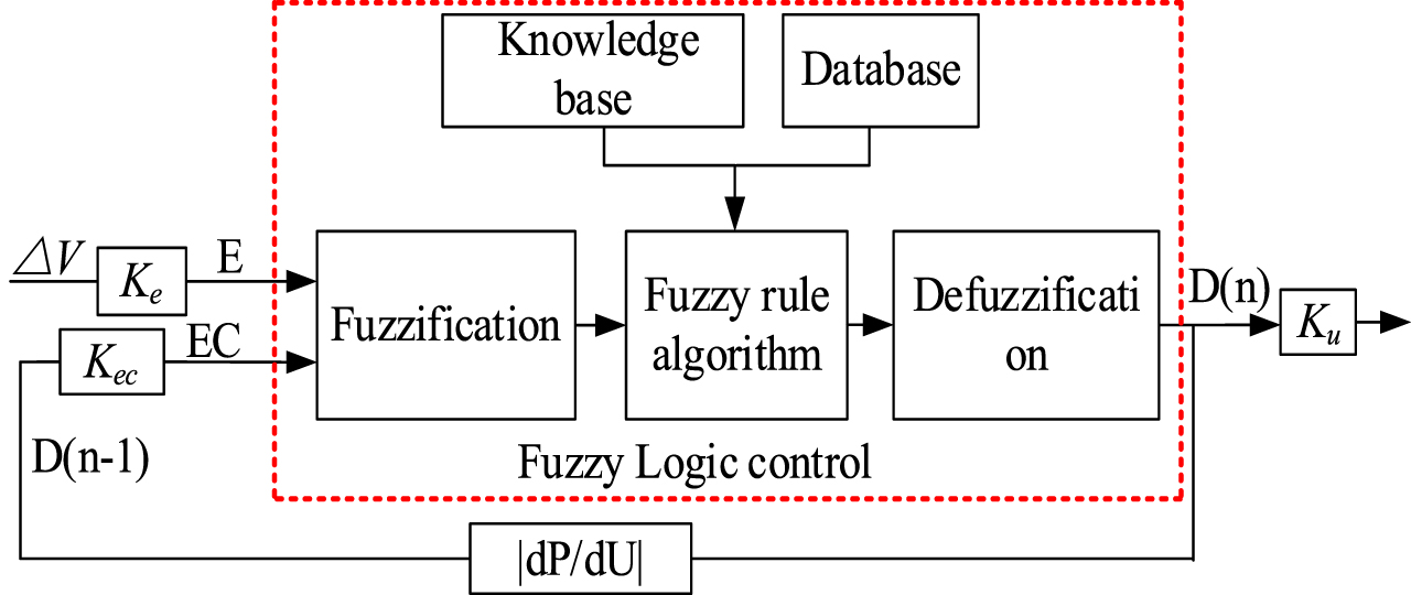
The structure of FLC.
The inputs ΔV, D(n-1) and the output D(n) of FLC are divided into the seven elements: ΔV, D(n-1), D(n)∈ {NB, NM, NS, Z0, PS, PM, PB}. NS is Negative Big; NM is Negative Middle; NS is Negative Small; Z0 is Zero; PS is Positive Small; PM is Positive Middle; PB is Positive Big. The domain of discourse is quantified as [–1,1]. Ke and Kec are the input quantization factors. Ku is the output scale factor. Ke, Kec and Ku are 1/280, 1/50 and 1/30, respectively. Figure 6 is the membership function of FLC. Table 2 is the FLC rule.

FLC membership function.
FLC rule
The flow chart of APSO-BP-FLC algorithm is shown in Fig. 7. The main steps are as follows: The irradiation and temperature are sampled as the inputs of PV system. The mutation operator is used to randomly initialize the position of each particle, and the NMSE function is selected as the loss function, as shown in Eq. (11). The optimal weight threshold of BP neural network is updated by APSO algorithm, and the optimized BP neural network is used to predict the MPP voltage (Vref) of PV cell. The inputs of FLC are the difference voltage (ΔV = Vpv - Vref) and duty ratio D(n-1) at the previous time, and the output is duty ratio D(n). Moreover, D(n-1) is optimized by the |dP/dU| to improve the search range of FLC. The PWM technology is employed to control on-off time of Mosfet. The specific parameters of APSO-BP-FLC algorithm are shown in Table 3

Flow chart of proposed algorithm.
APSO-BP-FLC parameters
Where: error is the difference between the sample value and true value; S is the sample value variance; l is the number of iterations.
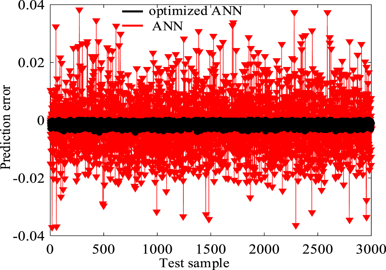
As shown in Fig. 8, the MSE and epochs of conventional BP neural network is 0.00011276 and 227, respectively. In contrast, the optimized BP neural network is 8.1366e–5 and 139. As shown in Fig. 9, the prediction error of conventional BP neural network is within [–0.04, 0.04]. Moreover, the optimized BP neural network is within [–0.005, 0.005]. In summary, the prediction accuracy and convergence rate of optimized ANN are greatly improved.

The error performance curve of (a) conventional BP neural network and (b) optimized BP neural network.
The best performance of conventional ANN and optimized ANN.
Simulation model and datasets
Figure 10 shows the PV system with the Boost converter. In this study, the APSO-BP-FLC algorithm is compared with APSO-BP, FLC and P&O algorithm to verify the feasibility and effectiveness of proposed algorithm. The simulation algorithm is Fixed-step (ode3). Eqs (12) and (13) are the calculation equation for steady-state oscillation rate α and efficiency η.
Where: α represents the steady-state oscillation rate; Psmax is the steady-state maximum power; Pmin is the steady-state minimum power; Pout is the output power of PV system; Pmax is the output power of PV system; i is the number of samples; m is the sampling time.

PV system under APSO-BP-FLC control.
Matlab is employed to obtain the input and output datasets based on the irradiation and temperature in a city in Shaanxi Province, China. The input is the irradiation and temperature, and the output is the MPP voltage. The input and output datasets are obtained by 10,000 cycles of Eqs. (14), (15) and (16). 70% of the datasets are the training sets and the rest is the testing sets.
Where: Gmax= 1000 W/m2; Gmin= 0 W/m2; Tmax= 40°C; Tmin= 10°C; rand is a random value in [0,1]; Vmps is the MPP voltage of the PV cell under standard test condition (STC, Gref= 1000 W/m2, Tref= 25°C); beta is the temperature coefficient (0.36901).
The design ideas are as follow:
The BP neural network has strong learning and reasoning abilities, hence first constructing it. However, the BP neural network cannot quickly track MPP, and the PV system has poor robustness. Therefore, the fuzzy logical control (BP-FLC) algorithm is employed to improve the stability and rapidity of BP neural network, while it is prone to waveform distortion under variable atmospheric conditions.
To proffer solutions to the mentioned above problems, the APSO algorithm is adopted to optimize the weight threshold of BP neural network (APSO-BP). The APSO-BP algorithm has fast tracking speed and strong stability. On the other hand, the output power partly oscillated under changing irradiation. At last, the APSO-BP-FLC algorithm is proposed to achieve error-free control.
The irradiation and temperature has strong influence on the photoelectric conversion efficiency in the actual PV system. The parameters of irradiation are as follow: 0 s 0.25 s, G = 0 W/m2, T = 0 °C; 0.25 s 0.5 s (Stage 1), G = 500 W/m2, T = 10 °C; 0.5 s 0.75 s (Stage 2), G = 700 W/m2, T = 20 °C; 0.75s 1 s (Stage 3), G gradually decreases from 1000 W/m2 to 900 W/m2, T = 40 °C; 1 s 1.25 s (Stage 4), G = 600 W/m2, T = 30 °C; 1.25 s 1.5 s, G = 0 W/ m2, T = 0 °C. The proposed algorithm is compared with P&O, FLC and APSO-BP algorithm. In addition, the voltage, current, power, efficiency of PV cell, and the output voltage, current, power and duty cycle of Boost converter are simulated in this study. The simulation results are shown in Figs. 11–18. The power waveform of PV cell is shown in Fig. 11.
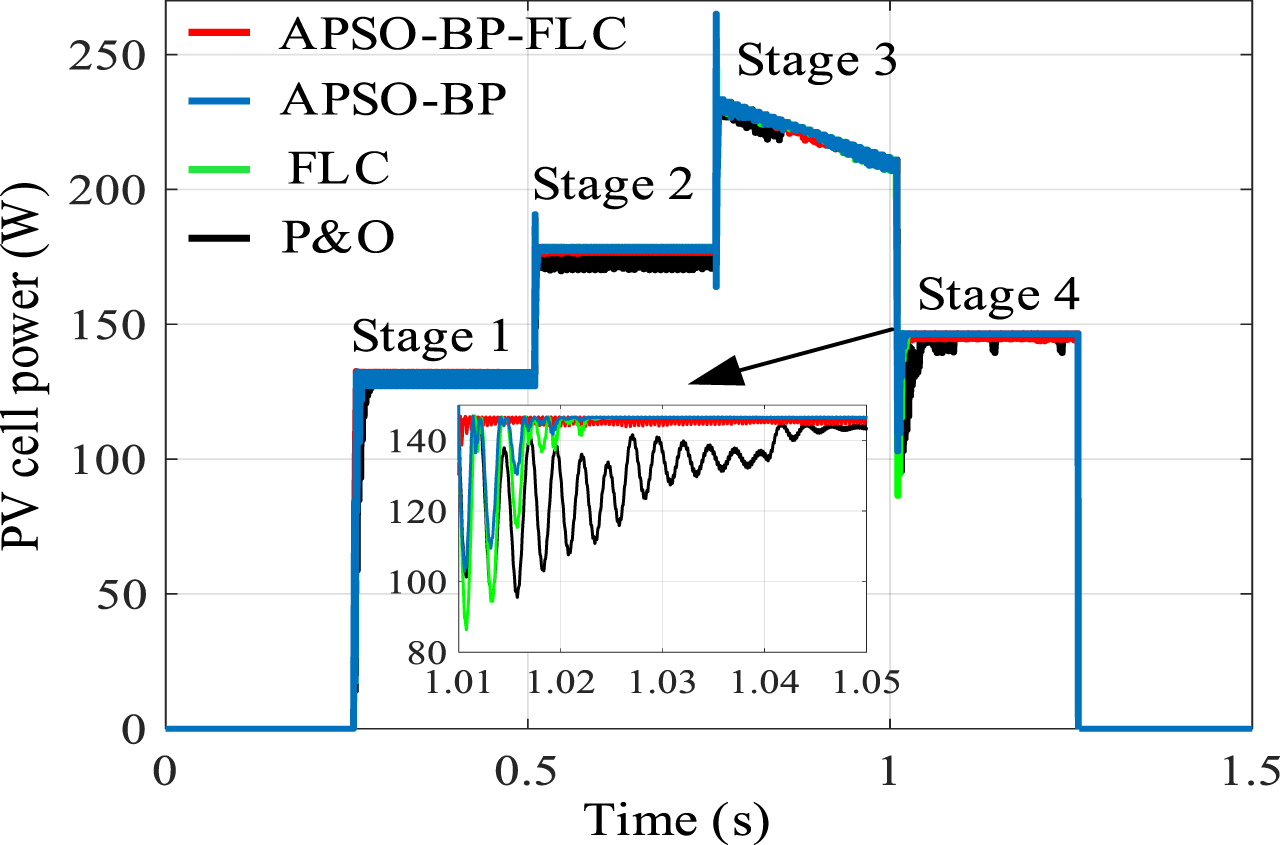
Power waveform of PV cell.

Voltage waveform of PV cell.
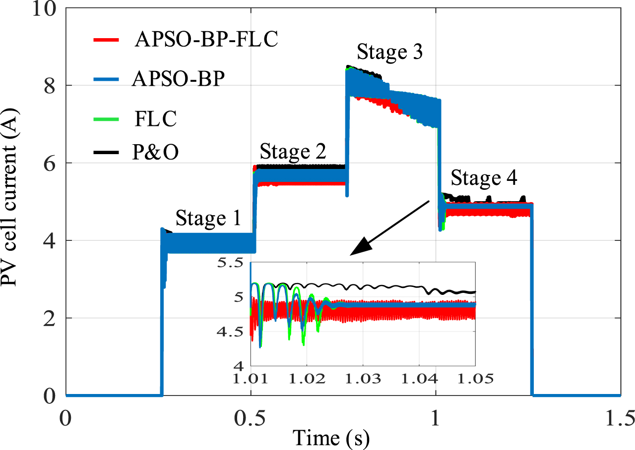
Current waveform of PV cell.

Efficiency.
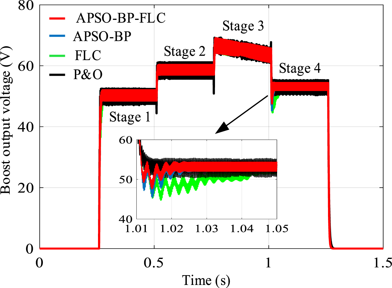
Boost circuit output voltage.

Boost output current.

Boost output power.

Boost circuit duty cycle.
As shown in Fig. 11, when G changes from 500 W/m2 to 700 W/m2 and then to 1000 W/m2, the tracking time to MPP of APSO-BP-FLC algorithm is 0.005 s and 0.004 s, respectively. In contrast, the tracking time to MPP of APSO-BP, FLC and P&O algorithm are 0.01 s, 0.03 s and 0.045 s, respectively. Moreover, the power oscillation amplitudes of APSO-BP-FLC, APSO-BP, FLC, and P&O algorithm are 1.5 W, 2 W, 7 W, and 10 W, respectively. It can be seen that the APSO-BP-FLC algorithm has lower steady-state oscillation rate. Figure 12 shows the voltage waveform of PV cell.
As shown in Fig. 12, the steady-state oscillation rate and MPP voltage of APSO-BP-FLC algorithm is 0.51% and 30.3 V, respectively. The steady-state oscillation rates of the three compared algorithms are 0.73 %, 5.1 % and 7.8%, and the MPP voltage of PV cell are 29.87 V, 28.96 V and 28.8 V, respectively. It is clearly that the proposed algorithm has faster tracking performance and higher robustness. Figure 13 shows the current waveform of PV cell.
As shown in Fig. 13, the MPP current of APSO-BP-FLC algorithm is 4.8A. In contrast, the three compared algorithms are 4.85A, 4.6A and 5.03A, respectively. It can be seen that the proposed algorithm has higher stability. Figure 14 shows the efficiency of PV cell.
As shown in Fig. 14, the efficiency of APSO-BP-FLC algorithm is 99.3%. In contrast, the three compared algorithms are 98.93%, 94.1% and 93.5%, respectively. The simulation results indicate that the proposed algorithm has higher stability and efficiency.
The output voltage, output current, output power and duty cycle of Boost circuit are shown in Fig. 15–18. The proposed algorithm can judge the boundary of P-U curve more preciser. Therefore, the proposed algorithm is superior to the three compared algorithm in all indicators. As shown in Fig. 18, the maximum duty cycle and minimum duty cycle are 0.85 and 0.45, respectively. It can prevent the Mosfet working normally. It is clearly that the APSO-BP-FLC algorithm can quickly track the MPP and the waveform distortion rate is lower.
In summary, the proposed algorithm has stronger tracking performance and stability. The specific results of each stage are shown in Table 4.
Specific results of each stage
Rain and snow weather will cause the low photovoltaic conversion efficiency of PV cell. Therefore, the simulation is carried out to further verify the effectiveness of APSO-BP-FLC algorithm under rapidly changing irradiation and temperature. Figure 19 shows the output power of PV cell when G changes from 500 W/m2 to 1000 W/m2, T decreases from 40°C to 30°C.
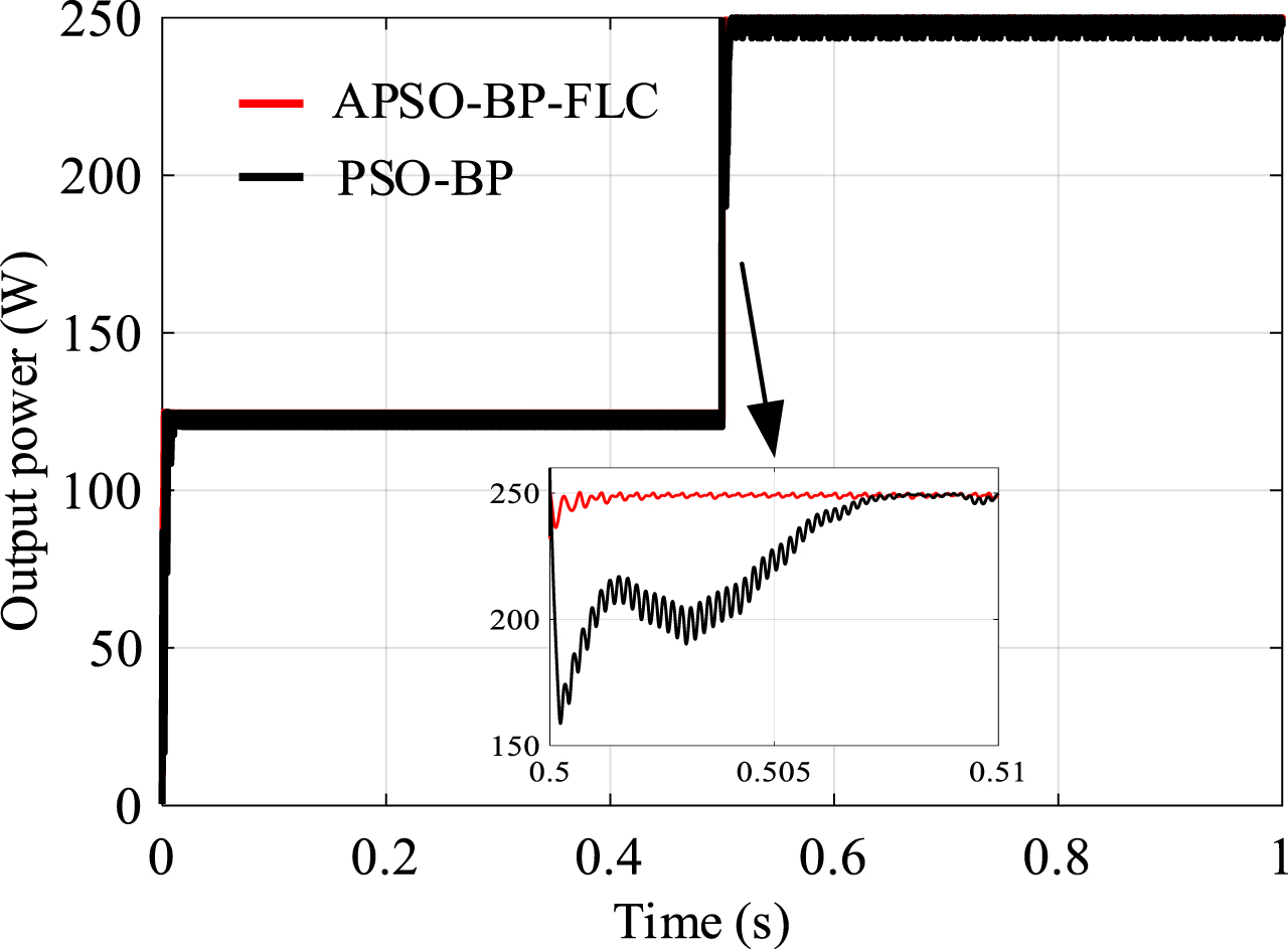
MPPT curve under rapidly changing G and T.
As shown in Fig. 19, the tracking time to MPP of PSO-BP algorithm is 0.007 s. The tracking time to MPP of APSO-BP-FLC algorithm is 0.003 s, and the steady-state oscillation rate is lower under the same conditions.
In conclusion, the proposed algorithm can quickly track MPP and has stronger anti-interference ability and stability.
PV cell have non-linear characteristics and the irradiation and temperature have a strong influence on the efficiency of PV cell. Since the BP neural network has a strong adaptability and reasoning performance, the FLC has a strong stability and the APSO algorithm has fast convergence speed. Hence, a APSO-BP-FLC algorithm is proposed to achieve error-free control.
The MPP voltage is directly predicted by optimized BP neural network. The fuzzy logical control is employed to adjust the duty cycle D(n) based on the voltage deviation value and duty cycle D(n-1) at the previous time. The simulation results show that the APSO-BP-FLC algorithm can quickly respond to external conditions and track MPP more accuracy. Concluding that the proposed algorithm has strong robustness and universality. The future work will adopt CNN to control the PV system.